Internode TG-789 User manual

1
TG-789 Broadband Gateway
Quick Setup Guide

2
Before you get started
Make sure you have an email or SMS from us advising that
your internet service is provisioned and ready to use.
Dear Internode Customer,
We are pleased to advise that your Internode broadband
service is now provisioned. Please quote Service ID A1234567
if you need to contact us for support.
Your Internode broadband is ready to use.
For support call 13 66 33. Ref: A1234567

3
What are you setting up today?
How to find out which type of internet you have:
Check your email and/or SMS from us about your internet order
or check the service details section of your customer invoice
TECHNOLOGY TYPE / PRODUCT TECHNOLOGY TYPE / PRODUCTSTART ON PAGE... START ON PAGE...
NodePhone (VoIP)19
Standard ADSL2+ 11
Naked ADSL2+ 6
NBN™Fibre to the Premises (FTTP)9
NBN™Fibre to the Node/Building (FTTN/B)
NBN™Fibre to the Curb (FTTC)
NBN™Hybrid Fibre-Coaxial (HFC)
7
8
6
Fibre Estates (OptiComm or OPENetworks) 12
NBN™Wireless 10
WiFi 18

4
1 2 4 6 83 5 7 9 10
STATUS WAN INTERNET WPS ETHERNET2.4GHz
WiFi
5GHzUSB WIRELESS
BUTTON
PHONE
Get to know your modem’s lights

5
Get to know your modem’s lights
Light State Meaning
STATUS Off Modem has no power.
Red Modem is offline.
Green Modem is online.
Orange Modem is rebooting or powering up.
Flashes during firmware upgrade.
WAN Off No connection or modem has no power.
Green Modem has a connection. Flashes
during connection activity.
Internet Off Modem has no power.
Red Modem is offline.
Green Modem is online. Flashes during
connection activity.
Wireless 2.4GHz
or 5GHz
Off WiFi off/disabled or modem has no power.
Green WiFi enabled. Flashes during WiFi
activity and when rebooting.
Light State Meaning
WPS Off WPS not in use or modem has no power.
Red WPS connection failed - try again.
Green WPS connection successful.
Orange WPS search mode on or WPS
connection in progress. Flashes.
Ethernet Off Nothing connected to LAN ports
or modem has no power.
Green Ethernet connection to any LAN port.
Flashes during connection activity.
USB Off No USB device detected.
Green USB device detected. Flashes
during connection activity.
NodePhone Off VoIP disabled or modem has no power.
Green VoIP enabled. Flashes during calls.
WiFi Button N/A A button you can press to turn
WiFi capability on/off.
6
123 4
Power Cable
Plug into a power outlet
Plug in for NBN™ FTTN/FTTB and Naked ADSL
Phone Cable
Plug into handset
(Optional)
1. Using the power cable supplied, connect your modem’s Power
port to a power outlet. Press the Power button on the back of
the modem to turn it on.
2. Use the supplied Phone cable to connect your modem’s grey
DSL port directly to the phone socket on the wall (remove any
other phone or fax devices). Do not use a line filter.
3. If you wish to use your VoIP phone service, connect a phone
handset to your modem’s Phone1 port.
4. You can use an additional Ethernet cable to connect your
computer to any of your modem’s 4 LAN ports. Alternatively,
follow the steps later in this guide to connect devices via WiFi.
Turn to Page 14 to continue setup.
Phone Cable
Plug into the phone
socket on the wall
Ethernet Cable
Plug into your computer’s
Ethernet Port (Optional)
7
Plug in for NBN™ FTTC
1. Using the power cable supplied, connect your modem’s Power
port to a power outlet. Press the Power button on the back of
the modem to turn it on.
2. Use the supplied Ethernet cable to connect your modem’s
red WAN port to the yellow GATEWAY port on your NBN™
Connection Device.
3. If you wish to use your VoIP phone service, connect a phone
handset to your modem’s Phone1 port.
4. You can use an additional Ethernet cable to connect your
computer to any of your modem’s 4 LAN ports. Alternatively,
follow the steps later in this guide to connect devices via WiFi.
Turn to Page 14 to continue setup.
Ethernet Cable
Plug into your computer’s
Ethernet Port (Optional)
Phone Cable
Plug into handset
(Optional)
Power Cables
Plug into 2 power outlets
NBN™ Connection Device
Connects to your modem via
Ethernet to the WAN Port
Phone Cable
Plug into the phone
socket on the wall
123 4
Before you get started...
If you received a new NBN™ Connection Box along with your modem, please follow its
setup guide to get it plugged in and turned on before you set up your modem.

8
Plug in for NBN™ HFC
1. Using the power cable supplied, connect your modem’s Power
port to a power outlet. Press the Power button on the back of
the modem to turn it on.
2. Use the supplied Ethernet cable to connect your modem’s red
WAN port to the UNI-D 1 port on your NBN™ Connection Box
(note that some boxes may have one yellow LAN port instead).
3. If you wish to use your VoIP phone service, connect a phone
handset to your modem’s Phone1 port.
4. You can use an additional Ethernet cable to connect your
computer to any of your modem’s 4 LAN ports. Alternatively,
follow the steps later in this guide to connect devices via WiFi.
Turn to Page 14 to continue setup.
Ethernet Cable
Plug into your computer’s
Ethernet Port (Optional)
Phone Cable
Plug into handset
(Optional)
Power Cables
Plug into 2 power outlets
Cable Socket
Connects to NBN™
Connection Box
NBN™ Connection Box
Connects to your modem via
Ethernet to the WAN Port
Before you get started...
If you received a new NBN™ Connection Box along with your modem, please follow
its setup guide to get it plugged in and turned on before you set up your modem.
123 4
9
Ethernet Cable
Plug into your computer’s
Ethernet Port (Optional)
Phone Cable
Plug into handset
(Optional)
POW ER
UNI-V1 UNI-V1
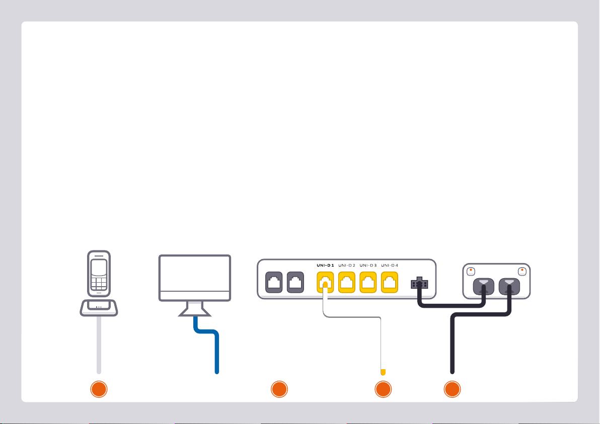
Plug in for NBN™ Fibre to the Premises
NBN™ Connection Box
Connects to your modem via
Ethernet to the WAN Port
1. Using the power cable supplied, connect your modem’s Power
port to a power outlet. Press the Power button on the back of
the modem to turn it on.
2. Use the supplied Ethernet cable to connect your modem’s red
WAN port to the UNI-D 1 port on your NBN™ Connection
Box. If UNI-D1 doesn’t work, try each UNI-D port before
contacting us for a hand.
Power Cables
Plug into 2 power outlets
3. If you wish to use your VoIP phone service, connect a phone
handset to your modem’s Phone1 port.
4. You can use an additional Ethernet cable to connect your
computer to any of your modem’s 4 LAN ports. Alternatively,
follow the steps later in this guide to connect devices via WiFi.
Turn to Page 14 to continue setup.
1243
10
POW ER
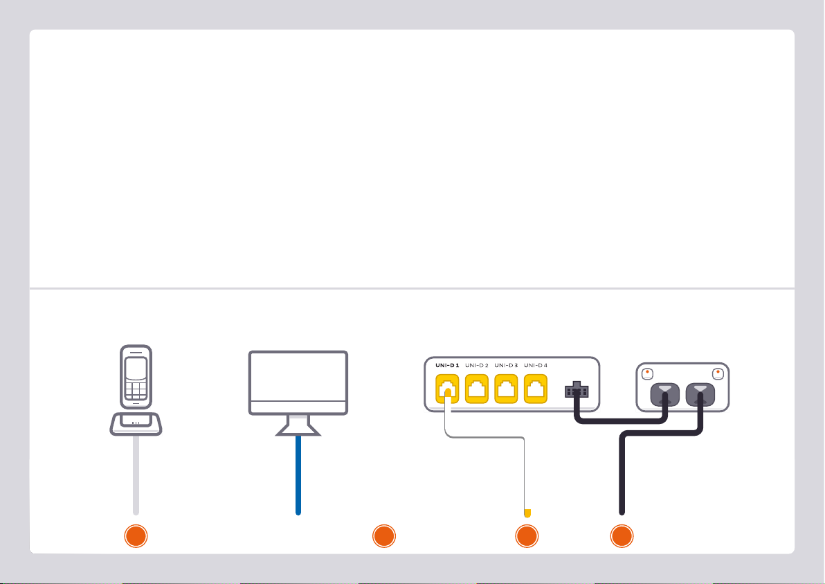
Plug in for NBN™ Wireless
1. Using the power cable supplied, connect your modem’s Power
port to a power outlet. Press the Power button on the back of
the modem to turn it on.
2. Use the supplied Ethernet cable to connect your modem’s red
WAN port to the UNI-D 1 port on your NBN™ Connection
Box. If UNI-D1 doesn’t work, try each UNI-D port before
contacting us for a hand.
3. If you wish to use your VoIP phone service, connect a phone
handset to your modem’s Phone1 port.
4. You can use an additional Ethernet cable to connect your
computer to any of your modem’s 4 LAN ports. Alternatively,
follow the steps later in this guide to connect devices via WiFi.
Turn to Page 14 to continue setup.
Ethernet Cable
Plug into your computer’s
Ethernet Port (Optional)
Phone Cable
Plug into handset
(Optional)
Power Cables
Plug into 2 power outlets
NBN™ Connection Box
Connects to your modem via
Ethernet to the WAN Port
123 4

11
PHONE ADSL
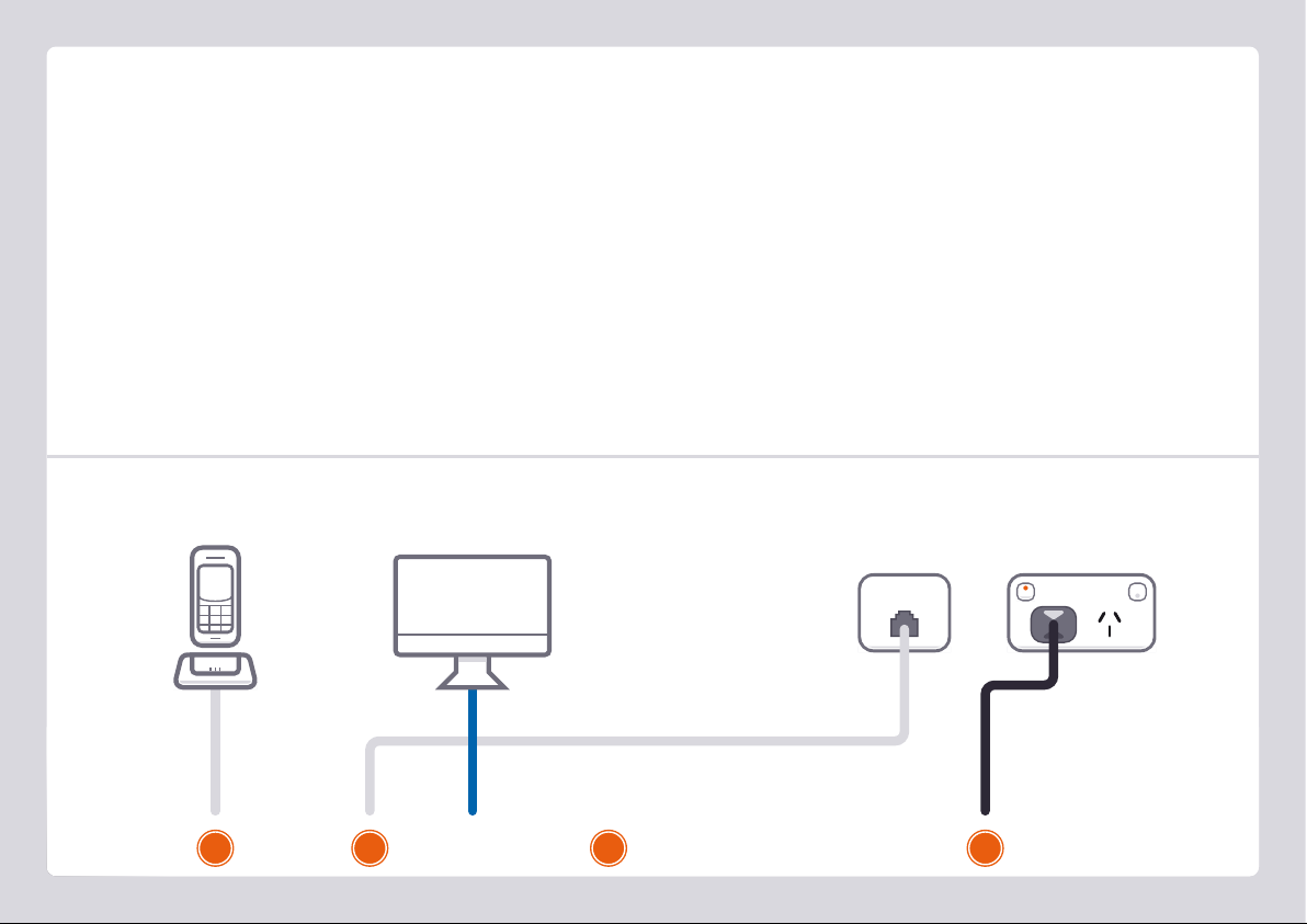
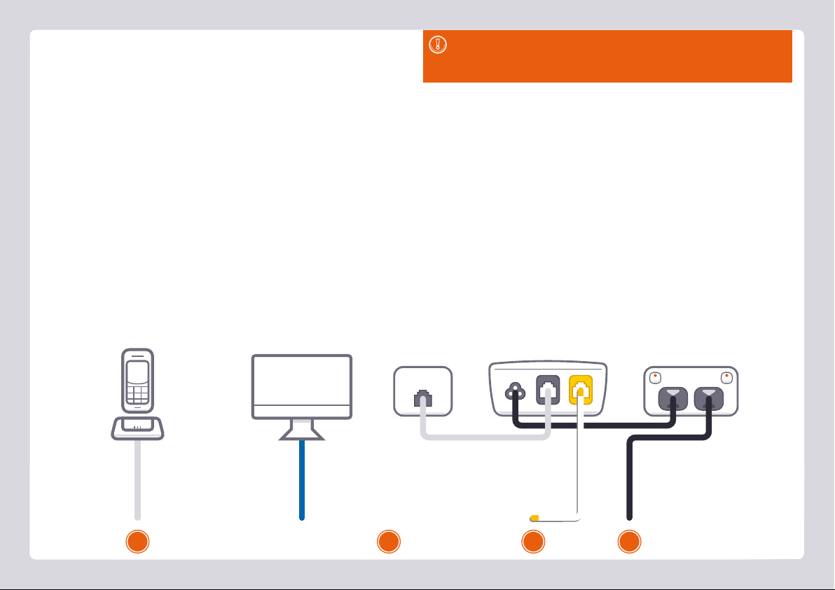
Plug in for Standard ADSL2+
1. Using the power cable supplied, connect your modem’s Power
port to a power outlet. Press the Power button on the back of
the modem to turn it on.
2. Use the supplied Phone cable to connect your modem’s grey
DSL port directly to the phone socket on the wall OR the ADSL
port on the line filter, then plug the line filter into the wall.
Note: Devices plugged into any other phone sockets in your
home should have a line filter.
3. If you wish to use your VoIP phone service, connect a phone
handset to your modem’s Phone1 port.
4. You can use an additional Ethernet cable to connect your
computer to any of your modem’s 4 LAN ports. Alternatively,
follow the steps later in this guide to connect devices via WiFi.
Turn to Page 14 to continue setup.
Power Cable
Plug into a power outlet
Phone Cable
Plug into the phone
socket on the wall
Phone Cable
Plug into handset
(Optional)
123 4
Line Filter
Only needed if you have ADSL
and you need to plug the modem
and a handset for Home Phone
into the same wall socket
Ethernet Cable
Plug into your computer’s
Ethernet Port (Optional)

12
POW ERLAN 1LAN 2LAN 3LAN 4
Plug in for Fibre Estates (OptiComm or OPENetworks)
1. Using the power cable supplied, connect your modem’s Power
port to a power outlet. Press the Power button on the back of
the modem to turn it on.
2. Use the supplied Ethernet cable to connect your modem’s red
WAN port to the LAN1 port on your Fibre Connection Box.
OPENetworks FTTN services will simply have a wall socket to
plug into instead.
Power Cables
Plug into 2 power outlets
3. If you wish to use your VoIP phone service, connect a phone
handset to your modem’s Phone1 port.
4. You can use an additional Ethernet cable to connect your
computer to any of your modem’s 4 LAN ports. Alternatively,
follow the steps later in this guide to connect devices via WiFi.
Turn to Page 14 to continue setup.
123 4
Ethernet Cable
Plug into your computer’s
Ethernet Port (Optional)
FTTH Connection Box
Connects to your modem via
Ethernet to the WAN Port
Phone Cable
Plug into handset
(Optional)

13
Getting Online
By default, your broadband settings should be pre-configured,
or they should configure automatically once your internet
service is ready and your modem is powered on for 15 minutes.
1. The Internet light on the front of your modem should be green.
2. The Phone light on the front of your modem should be solid
green if you have an active VoIP phone service and a handset
connected to the modem. See page 20 of this guide for more
details.
Is the internet light off?
Ensure that you received an email from us advising that your
internet service is fully provisioned.
• If you have, please turn to the next page to attempt a manual
configuration.
• If you haven’t received the email, your internet connection
isn't ready yet. Please check your last email from us for advice
on your connection appointment. It will include a reference
number in case you need to call us with any concerns.
STATUS WAN INTERNET WPS
WiFi
ETHERNET2.4GHz 5GHz USB
WIRELESS BUTTON
PHONE
1 2
14
You can log in to your modem settings to configure your
connection, or simply adjust your WiFi settings.
1. On your connected computer or WiFi device, open your web
browser and go to http://10.1.1.1
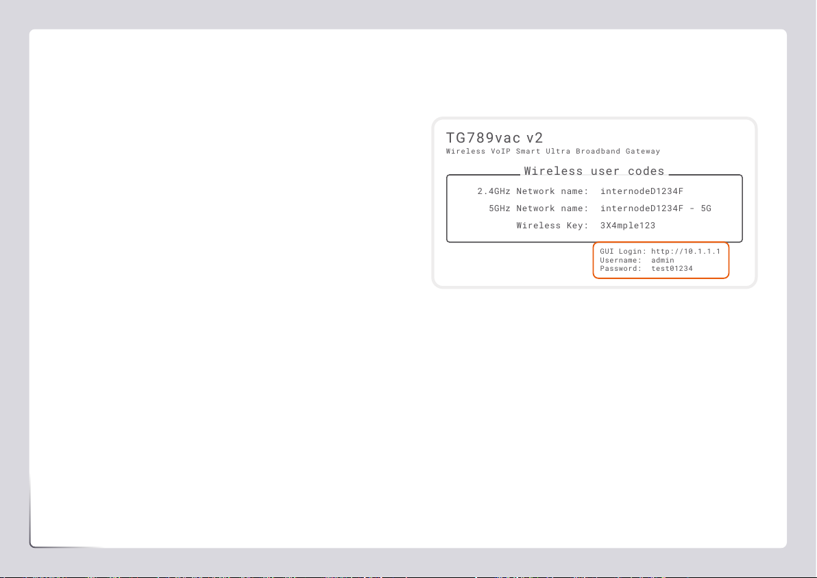
2. Log in with the default username and password, which can be
found under “GUI Login” on your modem’s barcode sticker.
3. The Setup Wizard should run; if not, simply click Setup Wizard
on the dashboard.
4. Select your provider from the Internet Service Provider list.
For the rest of the settings, refer to the table on the next
page for the type of internet that you have.
5. Click Next. If you have an active NodePhone (VoIP) service,
you can enter its details here. If you have Internode NBN
Phone, VoIP with another provider, or your NodePhone service
isn't ready yet, click “I don’t have VoIP”. You can set up VoIP
later with the steps on page 20.
6. Click Next, and then turn to page 15 to continue with your
manual configuration.
Manual Configuration (1 of 4)
TG789vac v2
Wireless VoIP Smart Ultra Broadband Gateway
Wireless user codes
2.4GHz Network name:
5GHz Network name:
Wireless Key:
internodeD1234F
internodeD1234F - 5G
3X4mple123
GUI Login: http://10.1.1.1
Username: admin
Password: test01234
TG789vac v2
Wireless VoIP Smart Ultra Broadband Gateway
Wireless user codes
2.4GHz Network name:
5GHz Network name:
Wireless Key:
internodeD1234F
internodeD1234F - 5G
3X4mple123
GUI Login: http://10.1.1.1
Username: admin
Password: test01234

15
Manual Configuration (2 of 4)
The different settings for different types of internet.
Type of Internet WAN Interface WAN Type VLAN Enabled Other Settings
ADSL / Naked ADSL PPP over Ethernet
You’ll also need to enter your username
and password as shown on the email
from us advising that your broadband
service has been fully provisioned.
Off VPI 8 / VCI 35
NBN™ HFC & FTTC Ethernet On VLAN ID 2
NBN™ FTTP Ethernet Off N/A
NBN™ FTTB / N VDSL Off N/A
NBN™ Wireless Ethernet Off N/A
OptiComm and
OPENetworks FTTH Estates
Ethernet Off N/A
OPENetworks FTTN Estates VDSL Off N/A

16
WiFi tip
If you're having trouble connecting to the WiFi, check the WiFi
lights on your modem. If they're off, your modem's Wireless on/
off button may have been pressed accidentally and turned off the
WiFi. Press the Wireless button again to turn the WiFi back on.
Manual Configuration (3 of 4)
If you wish to keep the default WiFi settings, simply leave all
boxes blank and click Next until you reach the Router Security
Settings step in the Setup Wizard, which is covered on the next
page.
1. Wireless 2.4GHz must be turned ON in order to connect to
this network. If SSID Broadcast is OFF, your network name
will not be visible to WiFi devices and you’ll have to enter it
manually to connect.
2. The 2.4Hz SSID Broadcast name is the name of your 2.4GHz
WiFi network. You can change this to anything you’d like.
3. Click Next and make sure Security Key Type/Security Mode
is set to WPA+WPA2 PSK.
4. The 2.4GHz Security Key is the password for your 2.4GHz
WiFi network. Change this to something that’s hard for others
to guess but easy for you to remember. You may wish to write
down your new WiFi details for future reference.
5. Click Next and run through steps 1-4 again for your 5GHz WiFi
network. Your modem has 2 WiFi networks which broadcast
on different frequencies. If your device(s) can’t connect to the
latest 5GHz network, use the 2.4GHz one.
6. Click Next and turn to the next page to continue with your
manual configuration.

17
Manual Configuration (4 of 4)
The Setup Wizard allows you to change the username and
password used to log in at http://10.1.1.1. This can be handy
if you have tenants or meddling teens and you don’t want
them to change your modem settings.
To keep the defaults, simply leave the boxes blank and click
Next. If you do set a custom username and/or password, you
should write it down and keep it somewhere safe.
All done!
If you can’t get online, see the back cover of this guide to
contact our friendly Support Team.
If you ever forget your custom login details, you can factory
reset the modem to return it to the default settings. However,
you will also lose all other custom settings, so you’ll need to set
up your modem again.
TG789vac v2
Wireless VoIP Smart Ultra Broadband Gateway
Wireless user codes
2.4GHz Network name:
5GHz Network name:
Wireless Key:
internodeD1234F
internodeD1234F - 5G
3X4mple123
GUI Login: http://10.1.1.1
Username: admin
Password: test01234
TG789vac v2
Wireless VoIP Smart Ultra Broadband Gateway
Wireless user codes
2.4GHz Network name:
5GHz Network name:
Wireless Key:
internodeD1234F
internodeD1234F - 5G
3X4mple123
GUI Login: http://10.1.1.1
Username: admin
Password: test01234
Internet address: http://10.1.1.1
Default username: admin
Default password: Printed on the sticker on
the base of your modem

18
Connecting via WiFi
Your modem’s WiFi has been pre-configured. You’ll find
the WiFi network name (SSID) and password (Wireless
Key) printed on a sticker on the base of your modem.
1. Make sure that WiFi is enabled on your computer, tablet,
smartphone or other WiFi device.
2. View the list of available WiFi networks on your WiFi device
and select the network that matches the network name on
your modem’s sticker.
3. Enter the WiFi password (wireless key) exactly as printed on the
sticker.
TG789vac v2
Wireless VoIP Smart Ultra Broadband Gateway
Wireless user codes
2.4GHz Network name:
5GHz Network name:
Wireless Key:
internodeD1234F
internodeD1234F - 5G
3X4mple123
GUI Login: http://10.1.1.1
Username: admin
Password: test01234
TG789vac v2
Wireless VoIP Smart Ultra Broadband Gateway
Wireless user codes
2.4GHz Network name:
5GHz Network name:
Wireless Key:
internodeD1234F
internodeD1234F - 5G
3X4mple123
GUI Login: http://10.1.1.1
Username: admin
Password: test01234
Your modem has 2 WiFi networks which share the same default
password but broadcast on different frequencies. We recommend
using the 5GHz network for the best experience, but if your device(s)
can’t connect to the latest 5GHz network, use the 2.4GHz one.
19
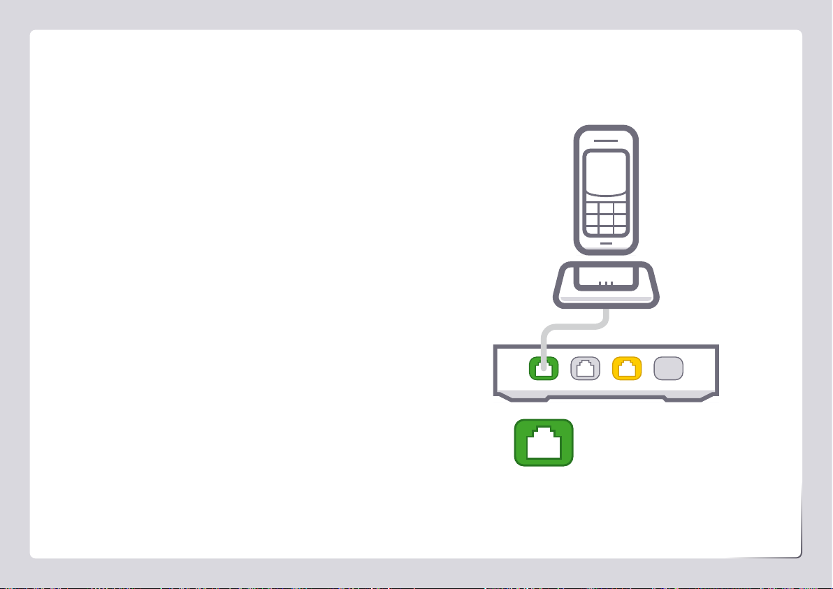
Phone 1
Setting up VoIP
If you didn’t set up VoIP in the Setup Wizard or you have a
third party VoIP provider, please follow the instructions on the
next page. If you have VoIP from a third party provider, you'll
need to contact them to confirm the correct VoIP settings.
Porting your existing phone number to VoIP?
If you’ve asked us to convert your existing phone
number to a VoIP service, please allow up to 7 days
after your internet service is active for this porting
process to complete. We’ll send you an email to confirm
when your VoIP service is active and ready to use.

20
Please note these instructions do not apply to Internode
NBN Phone.
1. On your connected computer or WiFi device, log in at
http://10.1.1.1. The default username and password can be
found under “GUI Login” on your modem’s barcode sticker.
2. Click Telephony on the dashboard. On the Global page,
underneath SIP Network, click the Edit button to the right
of the existing SIP Network entry. For NodePhone, enter the
following settings:
SIP Domain: sip.internode.on.net
Primary Registrar: sip.internode.on.net
Primary RegistrarPort: 5060
Primary Proxy: sip.internode.on.net
Primary ProxyPort 5060
Expire Time: 3600
3. Select the Phone Numbers tab and then click Create New,
entering the following settings:
Username: Your VoIP number
No spaces or brackets
URI: Your VoIP number
No spaces or brackets
Password: Your VoIP password
Case sensitive
Display Name: Your VoIP number
No spaces or brackets
SIP Network: SIP Network
Port: FXS
4. Click the Apply button to the right to save your settings. If
successful, Registered will show a green icon.
5. Try making a test call on a handset plugged into your modem’s
green Phone 1 port.
Setting up NodePhone
Other manuals for TG-789
2
Table of contents
Other Internode Gateway manuals


Popular Gateway manuals by other brands


ATI Technologies
ATI Technologies SA-ATM-2 user manual

Memco
Memco 452 003 installation guide

Grandstream Networks
Grandstream Networks GHP6 Series user manual

CellBounce
CellBounce CB34U quick start guide

4IPNET
4IPNET HSG320 Quick installation guide

TelcoBridges
TelcoBridges Tmedia TMG3200 System installation guide