SiboTech HTM-611 User manual

HART/Modbus
HART/Modbus
HART/Modbus
HART/Modbus Gateway
Gateway
Gateway
Gateway
HTM
HTM
HTM
HTM -
-
-
- 61
61
61
61 1
1
1
1
DATA
DATA
DATA
DATA
SHEET
SHEET
SHEET
SHEET
上海泗博自动化技术有限公司
SiboTech
SiboTech
SiboTech
SiboTech Automation
Automation
Automation
Automation Co.,
Co.,
Co.,
Co., Ltd.
Ltd.
Ltd.
Ltd.
Technical
Technical
Technical
Technical Support:
Support:
Support:
Support: +86-21-5102
+86-21-5102
+86-21-5102
+86-21-5102 8348
8348
8348
8348
E-mail:
E-mail:
E-mail:
E-mail: suppor[email protected]
support@sibotech.net
support@sibotech.net
support@sibotech.net
1
1
1
1 Product
Product
Product
Product Function
Function
Function
Function
HTM-611 is a gateway that achieving data communication between HART and
MODBUS. HART side can be configured as a primary master or the second ary master .
HTM-611 act as slave at the side of Modbus .
2
2
2
2 Product
Product
Product
Product Features
Features
Features
Features
�Application is simple: T he user simply refer to the product manuals and
application examples, configured according to the requirements then can achieve
communication in a short period of time.
�Powerful: S upport the interconnection between HART and MODBUS, transparent
transmission between HART and serial.
�Rich debugging functions:
V
isual display of data exchange, HART slave
command diagnosis and common debugging features are great ly convenien t to the
user's communication test.
3
3
3
3 Technical
Technical
Technical
Technical Specifications
Specifications
Specifications
Specifications
[1] HART can be used as a primary master or the second ary master .
[2] Support one HART-channel, multi-point mode using gateway internal resistance
support connecti ng 13 instrument s, and u sing an external resistor (250 Ω ) support

connecti ng 15 instrument s
[3] Support single-point and multi-point mode at the side of HART
[4] Single-point mode, support data burst operation of slave device
[5] Support all commands of the HART protocol
[6] Each HART command can be configured for change-of-state output, polling
output, initialization output or disable output
[7] HART per channel supports up to 128 user command s , HART output data buffer
up to 1000 bytes, and t he input data buffer up to 1600 bytes .
[8] Can choose to use an internal or external sampling resistor
[9] Serial RS232, RS485, RS232 optional , baud rate: 300K, 600K, 1200K, 2400K,
9600K, 19.2 K, 38.4K, 57.6K, 115.2Kbps optional
[10] Serial side can be configured for MODBUS slave, support function code: 03H,
04H, 06H, 10H .
[11] MODBUS slave support RTU and ASCII communication .
[12] The serial port can be configured as universal mode, and achieve transparent
data transmission with HART slave device s.
[13] Power: 24VDC (9V~30V), 80 mA (24VDC );
[14] Working circumstance temperature: -20~60 ℃, Humidity: 95%;
[15] External dimensions: (Width )40mm* (Height )125mm* (Depth)110mm;
[16] Installation: 35mm DIN RAIL;
[17] Protection Level: IP20;
4
4
4
4 Product
Product
Product
Product A
A
A
A ppearance
ppearance
ppearance
ppearance
Note: This picture is for reference only. Product appearance should accord to the
real object.
HART Interface
Digital tube
24VDC Interface
RS485/RS422
Interface
RS232 Interface
DIP switch
I ndicator s
4
4
4
4 .
.
.
. 1
1
1
1 Indicators
Indicators
Indicators
Indicators
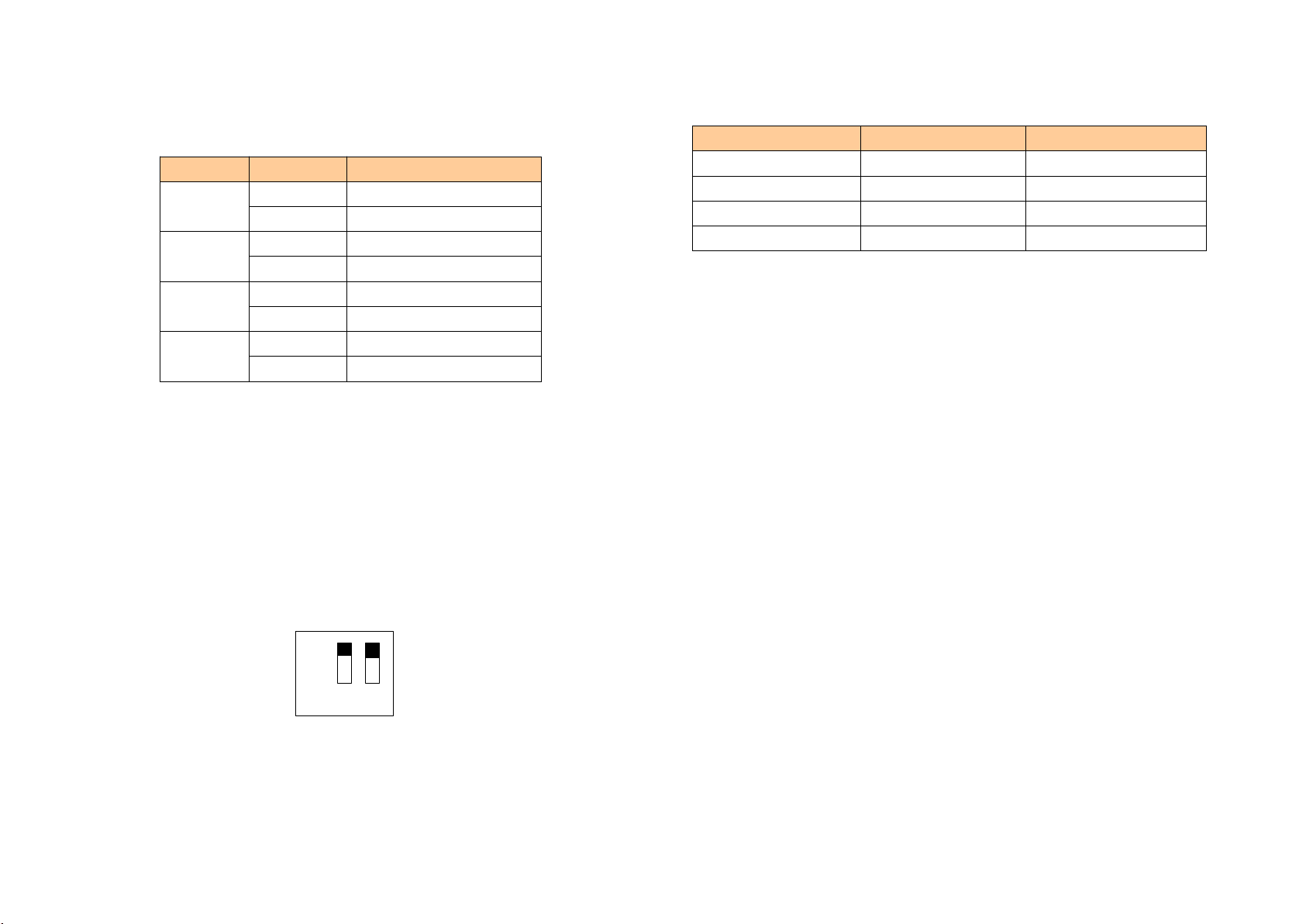
Indicator
Indicator
Indicator
Indicator State
State
State
State Status
Status
Status
Status Description
Description
Description
Description
PBF
Reserve Reserve
Reserve Reserve
STA
Reserve Reserve
Reserve Reserve
TX
Blinking Bus data is sending
Close No data is sending
RX
Blinking Bus data is receiving
Close No data is receiving
4
4
4
4 .
.
.
. 2
2
2
2 Configuration
Configuration
Configuration
Configuration S
S
S
S witch
witch
witch
witch
4
4
4
4 .
.
.
. 2
2
2
2 .1
.1
.1
.1 Status
Status
Status
Status setting
setting
setting
setting switch
switch
switch
switch
Configuration switch located at the bottom of product, bit 1 is the debugging bit
and bit 2 is the mode bit.
Note : ①After re-configure the switch, you have to restart the HTM-611 to make
the settings take effect!
②Set to debug mode, “ MODBUS slave ” or “ common mode ” will be
compulsory for RS485 interface for communication port, RS232 interface for
debugging interface.
③Configuration interface using the RS232 interface.
4
4
4
4 .
.
.
. 2
2
2
2 .2
.2
.2
.2 The
The
The
The MODBUS
MODBUS
MODBUS
MODBUS address
address
address
address set
set
set
set button
button
button
button
Under normal working condition of the HTM-611 , digital tube always displays
the address of the current Modbus address. Quickly press(double-click) the button
twice in succession, the high bit starts flash, and the low bit always on, click the button
to add 1 to start setting the Modbus address high bit. Long-press the button for 3
seconds, the high bit starts always on, and the low bit starts flash. Click the button to
add 1to start setting the MODBUS address low bit. Then long-press the button for 3
seconds, the address flashing three times shows that the address set successfully. If no
The
The
The
The debugging
debugging
debugging
debugging (bit
(bit
(bit
(bit 1)
1)
1)
1) Configuration
Configuration
Configuration
Configuration (bit
(bit
(bit
(bit 2)
2)
2)
2) Description
Description
Description
Description
Off Off Running mode
Off On Configuration Mode
On Off Debugging mode
On On Configuration Mode
Off
On 1 2

button action within ten seconds, HTM-611 exits the status of setting address and
continue to display the original address. HTM-611 settable range of MODBUS address
is 0 to 99 (decimal).
4
4
4
4 .
.
.
. 2
2
2
2 .3
.3
.3
.3 Internal
Internal
Internal
Internal /
/
/
/ external
external
external
external sampling
sampling
sampling
sampling resist
resist
resist
resist ance
ance
ance
ance switch
switch
switch
switch
H T M- 611 can choose using the internal sampling resist ance or external sampling
resist ance for HART signal . The specifications of the internal resistance is 270 Ω , 2W.
When the power of the sampling resist ance is more than
2W,
you must use an external
resist ance .
Switch
Switch
Switch
Switch to
to
to
to the
the
the
the top,
top,
top,
top, using
using
using
using the
the
the
the internal
internal
internal
internal
sampling
sampling
sampling
sampling resist
resist
resist
resist ance
ance
ance
ance
270 Ω
Switch
Switch
Switch
Switch to
to
to
to the
the
the
the bottom,
bottom,
bottom,
bottom, us
us
us
us ing
ing
ing
ing an
an
an
an
external
external
external
external sampling
sampling
sampling
sampling resist
resist
resist
resist ance
ance
ance
ance
4
4
4
4 .
.
.
. 3
3
3
3 Interface
Interface
Interface
Interface
4
4
4
4 .
.
.
. 3
3
3
3 .1
.1
.1
.1 Power
Power
Power
Power Interface
Interface
Interface
Interface
GND
NC
24V+
1
2
3
4
4
4
4 .
.
.
. 3
3
3
3 .2
.2
.2
.2 RS-485/RS-422
RS-485/RS-422
RS-485/RS-422
RS-485/RS-422 interface
interface
interface
interface
GND
D-
D+
1
2
3
4
5
R-
R+
Pin
Pin
Pin
Pin Function
Function
Function
Function
1 GND
2 NC(No Connect)
3 24V+ ,DC plus 24V
270 Ω
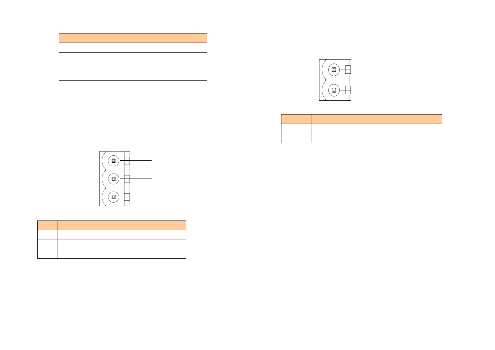
Pin
Pin
Pin
Pin Function
Function
Function
Function
1 R-, RS-422 Receive Negative
2 R+, RS-422 Receive Positive
3 GND
4 D-, RS-485/RS-422 Transmit Negative
5 D+, RS-485/RS-422Transmit Positive
4
4
4
4 .
.
.
. 3
3
3
3 .3
.3
.3
.3 RS-232
RS-232
RS-232
RS-232 interface
interface
interface
interface
RS-232 interface uses a 3-pin pluggable open terminal, and its pin description is
shown as follows:
RX
TX
GND
1
2
3
4
4
4
4 .
.
.
. 3
3
3
3 .4
.4
.4
.4 HART
HART
HART
HART interface
interface
interface
interface
1
2
HART LOOP+
HART LOOP-
Pin
Pin
Pin
Pin Function
Function
Function
Function
1 Connect HART signal positive
2 C onnect HART signal negative
Pin
Pin
Pin
Pin Function
Function
Function
Function
1 RX , Connect user device RS232's RX
2 TX , Connect user device RS232's TX
3 GND , Connect user device RS232's GND
5
5
5
5 Topology
Topology
Topology
Topology of
of
of
of HTM-611
HTM-611
HTM-611
HTM-611
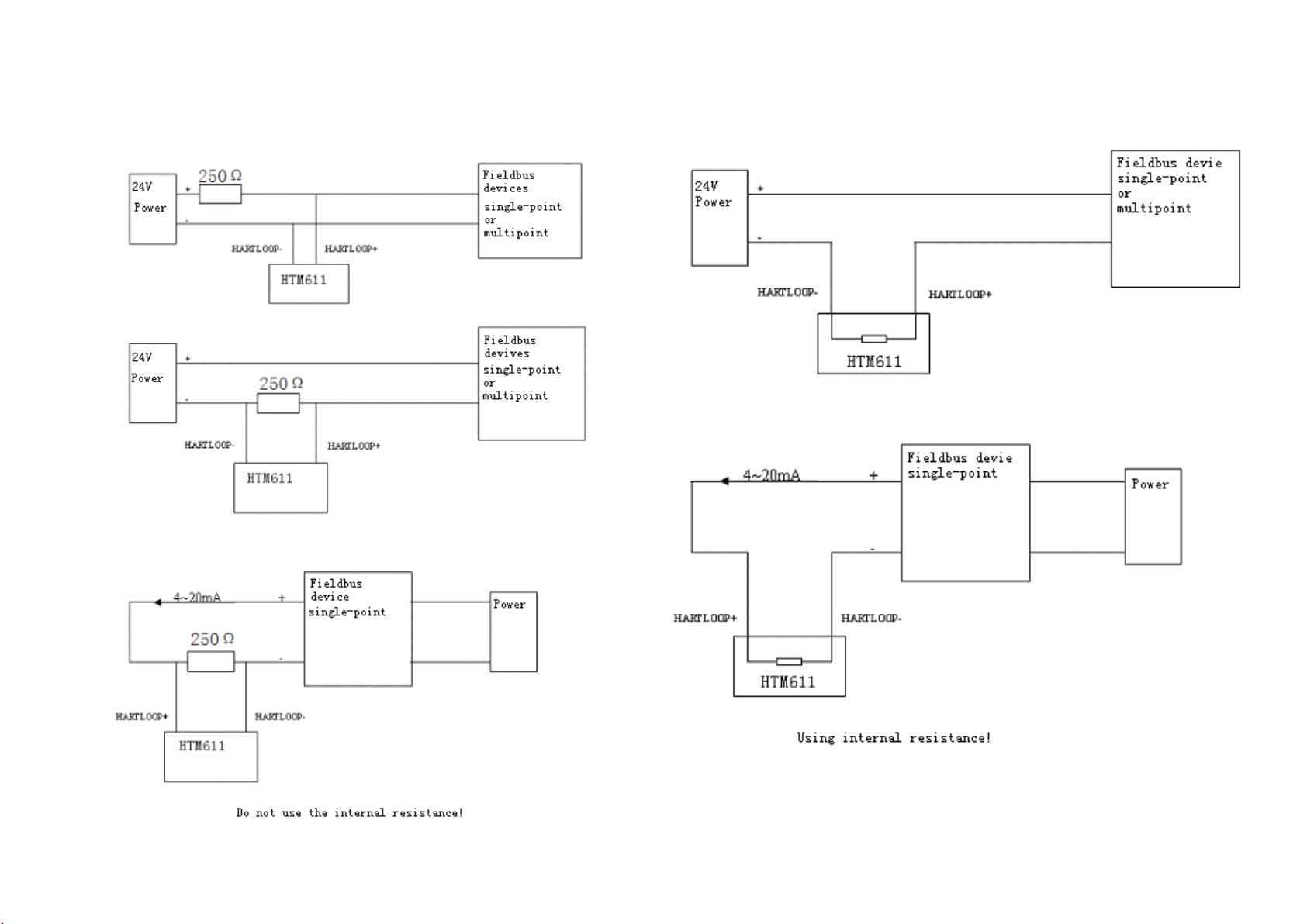
Note:
Note:
Note:
Note: 1 . Some HART slave instrument need to perform self-test and other internal
work when power on, may not proceed HART communication then gateway can not

receive the response of the instrument right now. Recommendations to the HART slave
instrument and gateway separate power supply, so that the gateway can immediately
establish communication with instrument.
2 . When configuration HART commands in the software HT-123 , the
commands need to be configured according to the actual needs. To improve the speed
of bus communication, it is recommended not to configure the empty node (in fact, not
connected to the node) and empty commands(the actual unwanted commands).
6
6
6
6 Installation
Installation
Installation
Installation Method
Method
Method
Method
Using 35mm DIN RAIL
7
7
7
7 Machine
Machine
Machine
Machine Dimension
Dimension
Dimension
Dimension
Size: 40mm (weight)*125mm (height)*110mm (depth)
Other SiboTech Gateway manuals


Popular Gateway manuals by other brands


enphase
enphase Envoy Communications Gateway Quick install guide

Huawei
Huawei ME60 Series Emergency Maintenance

Cisco
Cisco 3527 PRI G Installation and upgrade guide

Clavister
Clavister SG10 Series Installation and setup guide

Frama
Frama F-Link installation manual

Tyco
Tyco Visonic PowerMaster-360 user guide