Interpump Group Pralissoli S1510 User manual

S1510
VALVOLA DI MASSIMA PRESSIONE
RELIEF VALVE
SOUPAPE DE LIMITATION DE LA PRESSION
HÖCHSTDRUCKVENTIL
ISTRUZIONI D’USO
OPERATING INSTRUCTIONS
MODE D’EMPLOI
BEDIENUNGSANLEITUNG

- 2-

- 3-
======================================================
INDEX
ITALIANO…………………………... pag. 5
ENGLISH………………………….... p. 7
FRANÇAIS………………………..... p. 9
DEUTSCH………………………….. S. 11
======================================================

- 4-
DIMENSIONI - DIMENSIONS
CONNESSIONE - CONNECTION
SP:Pressione di taratura
WP: Pressione di lavoro
SP: Set pressure
WP: Work pressure
TENUTA CONICA
CONICAL SEAL
Cod.083200210
COPPIA
TORQUE
70 Nm

- 5-
«Istruzioni originali»
IL PRESENTE LIBRETTO FORNISCE LE
INDICAZIONI PER L’INSTALLAZIONE, L’USO E LA
MANUTENZIONE DELLA VALVOLA, PERTANTO E’
PARTE INTEGRANTE DELLA STESSA E QUINDI
DEVE ESSERE LETTO ATTENTAMENTE PRIMA DI
OGNI ATTIVITA’E CONSERVATO CON CURA.
RISPETTARE RIGOROSAMENTE QUANTO
SCRITTO AL FINE DI UN IMPIEGO SICURO ED
EFFICACE DELLA VALVOLA.
IL MANCATO RISPETTO, OLTRE AL
DECADIMENTO DELLA GARANZIA, PUÒ CAUSARE
GUASTI PREMATURI E CREARE SITUAZIONI DI
PERICOLO.
1- INFORMAZIONI GENERALI
1.1- La valvola di massima pressione S1510 è un
dispositivo a taratura manuale e azionato a pressione che,
in funzione della sua regolazione, quando la pressione
all’interno della pompa/impianto supera il valore di taratura
scarica l’acqua in eccesso riducendo la pressione. Il
ripristino delle normali condizioni di lavoro avviene
spegnendo e riavviando l’impianto.
1.2- Considerando che la valvola S1510 è utilizzata
unitamente ad una pompa/impianto per acqua ad alta
pressione, denominato successivamente solo impianto,
l’installazione e l’utilizzo devono essere adeguati al tipo di
impianto impiegato e coerenti con le norme di sicurezza
vigenti nel paese di utilizzo.
1.3- Prima di utilizzare la valvola assicurarsi che l’impianto
al quale è incorporata sia stato dichiarato conforme alle
disposizioni delle relative Direttive e/o norme.
1.4- Prima dell’installazione e utilizzo della valvola ricevuta
consigliamo di controllare la sua integrità e verificare che le
caratteristiche di targa corrispondano a quelle richieste. In
caso contrario non utilizzare la valvola e contattare il
servizio assistenza Interpump Group per eventuali
indicazioni.
2- IMBALLO
2.1- Effettuare la movimentazione degli imballi rispettando
le indicazioni riportate sugli imballi stessi e/o fornite dal
costruttore.
2.2- Nel caso in cui la valvola non sia utilizzata
immediatamente è necessario immagazzinarla nell’imballo
integro e in aree protette dalle intemperie, dall’eccessiva
umidità e dai raggi solari diretti. Inoltre è bene interporre tra
il pavimento e l’imballo pianali di legno o di altra natura, atti
ad impedire il diretto contatto con il suolo.
2.3- Smaltire gli elementi dell’imballo in accordo alle
disposizioni legislative vigenti in materia.
3- ISTRUZIONI PER L’INSTALLAZIONE:
3.1- La pressione di taratura SP è regolata e fissata
tramite sigillatura da Interpump Group e non può
essere modificata. I valori della pressione di taratura e
della massima pressione di lavoro consigliata WP sono
riportati sulla valvola.
3.2- La portata massima dipende dalla pressione di taratura
ed è compresa tra 51.5 e 100 L/min. Il valore esatto è
riportato sulla valvola.
3.3- La pressione di taratura SP è quella pressione alla
quale la valvola interviene determinando il valore massimo
di pressione raggiungibile nell’impianto.
3.4- L’installazione deve essere fatta da personale
qualificato e autorizzato, con le competenze necessarie per
lavorare su impianti ad alta pressione e con la conoscenza
delle istruzioni d’uso e sicurezza riportate su questo libretto.
3.5- Il sistema di fissaggio e di tenuta della valvola S1510 è
pensato per pompe e/o prodotti Interpump Group.
3.6- La tenuta sul raccordo G1/2 è realizzata tramite la
pastiglia conica cod.083200210.
3.7- Prima di installare la valvola ingrassare leggermente il
filetto G1/2 con grasso specifico per altissime pressioni EP
(extreme pressure) contenente Grafite o Molibdeno, quindi
serrare il raccordo con chiave dinamometrica a 70Nm.
ATTENZIONE: Durante l’utilizzo in nessun caso
superare i valori massimi di pressione, portata
e temperatura indicati nel libretto e/o riportati
sulla valvola.
ATTENZIONE: Per il corretto utilizzo della
valvola è necessario installarla nella zona
dell’impianto che durante l’uso raggiunge la
pressione maggiore. Inoltre consigliamo di
posizionarla in prossimità del componente che
si desidera maggiormente proteggere dai
picchi di pressione.
= ITALIANO =
CARATTERISTICHE TECNICHE
PORTATA CAMPO PRESSIONE di TARATURA TEMP.
max MASSA
min - max min - max °C °F kg lbs
20 –100
5,2–26,4
l/min
g.p.m.
(USA)
48 –180
480 –1800
6960 –26105
MPa
bar
p.s.i.
30 70 2,7
5,95

- 6-
4- AVVERTENZE D’UTILIZZO
4.1- E’responsabilità dell’installatore fornire le adeguate
istruzioni all’Utilizzatore finale per il corretto utilizzo
dell’impianto sul quale la valvola sarà installata.
4.2- Per il collegamento della valvola all’impianto utilizzare
raccordi adeguatamente dimensionati alle prestazioni della
valvola stessa.
4.3- Utilizzare esclusivamente acqua dolce e filtrata.
L’impiego di acqua salata e/o contenente particelle solide di
dimensioni superiori a 20µm, provoca una rapida usura
degli organi interni della valvola compromettendo il corretto
funzionamento. E’possibile additivare l’acqua aggiungendo
detergenti poco aggressivi, biodegradabili e comunque
conformi alle norme vigenti nel Paese d’utilizzo.
4.4- Negli impianti per la produzione di acqua
calda la temperatura del liquido a contatto con la
valvola deve sempre essere inferiore al valore
indicato sul libretto e sulla valvola stessa. Evitare
la formazione di vapore o acqua surriscaldata.
4.5- Prima della messa in servizio dell’impianto consigliamo
di verificare la corretta installazione delle attrezzature
effettuando una prima accensione di collaudo.
4.6- ATTENZIONE: In nessun modo ostruire o
coprire la zona della valvola predisposta allo
scarico dell’acqua. Non cercare di convogliare
l’acqua scaricata, ma disperderla sempre in
atmosfera. Non rispettare queste semplici
indicazioni significherebbe compromettere la
sicurezza dell’impianto.
4.7- Per ottimizzare l’abbinamento pompa-valvola è
necessario limitare il campo d’utilizzo della valvola in
funzione della pressione e portata della pompa a una
potenza massima di 150 kW (201 HP). Questo significa
utilizzare pompe, come si vede dal grafico, che per
pressioni massime di lavoro di 150MPa (1500bar-21755psi)
producono portate di circa 51.5 L/min e per portate
massime di 100L/min generano pressioni di circa 77.5 MPa
(775 bar –11240 psi).
.
4.8- In caso di intervento della valvola di massima
pressione spegnere l’impianto ed individuare la causa
dell’innalzamento della pressione.
5- MANUTENZIONE
5.1- L’eventuale manutenzione e/o riparazione deve essere
effettuata esclusivamente da Interpump Group.
5.2- Consigliamo almeno ogni 2 anni o al
raggiungimento delle 500 ore di lavoro
dell’impianto di eseguire una verifica
d’intervento della valvola per constatare la
corrispondenza con la pressione di taratura.
5.3- La valvola è costituita interamente da materiali non
tossici o pericolosi, comunque, in caso di rottamazione,
consigliamo di non disperderla nell’ambiente ma
consegnarla presso un centro di smaltimento autorizzato o
rivolgersi al più vicino Centro di Assistenza Autorizzato
INTERPUMP GROUP.
ATTENZIONE: Per nessun motivo manomettere
la valvola e/o utilizzarla per scopi diversi da
quelli per i quali è stata prodotta.
In caso contrario il costruttore declina ogni
responsabilità sul funzionamento e sulla
sicurezza della stessa.
6- CONDIZIONI DI GARANZIA
6.1- Il periodo e le condizioni di garanzia sono contenute
nel contratto di acquisto.
6.2- La garanzia perde validità se la valvola è usata per
scopi impropri, utilizzata con prestazioni superiori a quelle
dichiarate, riparata con ricambi non originali o se risulta
danneggiata per l’inosservanza delle istruzioni d’uso o per
manomissioni non autorizzate.
Le informazioni presenti su questo libretto possono essere variate senza
preavviso.
Copyright
Il contenuto di questo libretto è di proprietà di Interpump Group.
Le istruzioni contengono descrizioni tecniche ed illustrazioni che
non possono essere copiate e/o riprodotte interamente od in parte
né passate a terzi in qualsiasi forma e comunque senza
l’autorizzazione scritta della proprietà.
I trasgressori saranno perseguiti a norma di legge con azioni
appropriate.

- 7-
«Translated from original instructions»
THIS DOCUMENT PROVIDES THE INSTRUCTIONS FOR
THE INSTALLATION, USE AND MAINTENANCE OF THE
VALVE, THEREFORE IT IS AN INTEGRAL PART OF
THE VALVE ITSELF AND MUST BE READ CAREFULLY
BEFORE ANY USE AND KEPT WITH CARE.
STRICTLY COMPLY WITH THE INSTRUCTIONS
CONTAINED IN THIS DOCUMENT IN VIEW OF A SAFE
AND EFFECTIVE USE OF THE VALVE.
FAILURE TO COMPLY WITH THESE INSTRUCTIONS
MIGHT CAUSE EARLY FAULTS AND RESULT IN
SITUATIONS OF DANGER, IN ADDITION TO VOIDING
ANY WARRANTY.
1- GENERAL INFORMATION
1.1- The S1510 relief valve is a manually-adjustable,
pressure-operated device which, according to its
setting, releases the excess of water when the pressure
inside the pump/system exceeds the adjusted value,
thus reducing the pressure. The normal working
conditions can be restored by turning off and then
restarting the system.
1.2- Since the S1510 valve is used in connection with a
high pressure water pump/system, which shall be called
hereafter only “system”, installation and use must be
suited to the type of system used and comply with the
safety Regulations in force in the Country where the
valve is used.
1.3- Before using the valve, make sure that the system
the valve is used with is certified to comply with the
relevant Directives and/or Regulations.
1.4- Before installing and using the valve for the first
time, we suggest you check that it is undamaged and
make sure that the rated features correspond to the
required ones. If this is not the case, do not use the
valve and contact the after-sales service of Interpump
Group for information.
2- PACKAGE
2.1- Packages must be handled in compliance with the
instructions stated on the packages themselves and/or
provided by the manufacturer.
2.2- In case the valve is not used immediately, it must
be stored in its integral package and placed in areas
which are not exposed to the weather and which are
protected from excessive humidity and from direct
sunlight. Moreover, it is advisable to place wooden
pallets or other types of pallets between the package
and the floor, in order to prevent the direct contact with
the ground.
2.3- The package components must be disposed of in
compliance with the relevant laws in force.
3- INSTRUCTIONS FOR INSTALLATION:
3.1- The setting pressure (SP) is adjusted and fixed
by sealing by Interpump Group and cannot be
changed. The values of the setting pressure and
suggested maximum working pressure (WP) are
stated on the valve.
3.2- The maximum flow rate depends on the setting
pressure and ranges from 51.5 to 100 l/min. The exact
value is stated on the valve.
3.3- The setting pressure (SP) is the pressure at which
the valve opens, thus determining the maximum
pressure value that the system cannot exceed.
3.4- The installation must be made by qualified and
authorized staff only, who must have the required skills
to handle high pressure systems and be informed of the
operating and safety instructions contained in this
document.
3.5- The fastening and sealing system of the S1510
valve is designed for Interpump Group pumps and/or
products.
3.6- The seal of the G1/2 fitting is made by conical seal
part no. 083200210.
3.7- Before installing the valve, slightly lubricate the
G1/2 thread with a grease specific for very high
pressures (EP-extreme pressure) containing Graphite
or Molybdenum, then tighten the fitting by means of a
dynamometric wrench (70 Nm).
IMPORTANT: During use, never exceed the
maximum values of pressure, flow-rate and
temperature as stated in this document
and/or indicated on the valve.
IMPORTANT: For a correct use of the
valve, it is necessary to install it in the area
of the system reaching the higher pressure
during use. Moreover, we suggest you
install it by the component that you wish to
protect most from pressure peaks.
= ENGLISH =
TECHNICAL FEATURES
FLOW RATE SETTING PRESSURE RANGE Max
TEMP. MASS
min - max min - max °C °F kg lbs
20 –100
5,2–26,4
l/min
g.p.m.
(USA)
48 –180
480 –1800
6960 –26105
MPa
bar
p.s.i.
30 70 2,7
5,95

- 8-
4- WARNINGS
4.1- The installer must provide the ultimate consumer
with the proper instructions for the correct use of the
system the valve will be used in connection with.
4.2- The fittings used to connect the valve to the system
must be suited to the valve performance features.
4.3- Use soft and filtered water only. In case of salt
water and/or of water containing solid particles of a size
exceeding 20µm, the internal components of the valve
will be subject to quick wear; furthermore, this might
compromise the correct functioning of the valve.
Addition agents can be used in the water, provided that
they are delicate, biodegradable and always complying
with the Regulations in force in the Country where the
valve is used.
4.4- In the systems for hot water production,
the temperature of the liquid that comes into
contact with the valve must always be lower
than the value stated in this instruction
manual and indicated on the valve itself.
Avoid the formation of steam or
overheated water.
4.5- Before operating the system, it is advisable to start
it for a preliminary test run in order to check that the
system is properly installed.
4.6- IMPORTANT: Do not obstruct or
cover the water discharge area of the
valve in any way . Do not try and convey
the discharged water; instead, always
release in the atmosphere. Failure to
comply with these simple instructions
will result in a reduced safety of the
system.
4.7- In order to optimize the pump-valve coupling, it is
necessary to keep the valve operation range, as a
function of the pump pressure and flow rate, within a
maximum power of 150 kW (201 HP). As shown in the
chart, this means using pumps producing a flow rate of
approx. 51.5 l/min. for maximum working pressures of
150 MPa (1500 bar - 21755 psi), and generating a
pressure of approx. 77.5 MPa (775 bar-11240 psi) for
maximum flow rates of 100 l/min.
4.8- Should the relief valve open, turn off the system
and find out what is the cause of the pressure increase.
5- MAINTENANCE
5.1- Any maintenance and/or repair must be carried out
by Interpump Group only.
5.2- We suggest you check, at least every 2
years or after reaching 500 working hours
of the system, that the valve opens
correctly in order to verify the
correspondence with the setting pressure.
5.3- The valve is entirely made of non-toxic and safe
materials; however, in case of disposal, we suggest you
do not disperse it in the environment but take it to an
authorized disposal centre or contact the nearest
INTERPUMP GROUP Authorized Service Centre.
IMPORTANT: The valve shall not be
tampered with for any reason and/or used
for any purpose other than the use it has
been designed for. In case of tampering,
the manufacturer disclaims all
responsibility as to the valve functioning
and safety.
6- WARRANTY CONDITIONS
6.1- The period and conditions of warranty are specified
in the purchase contract.
6.2- Warranty is voided in case the valve is used for
improper purposes, used at higher performances than
the rated ones, repaired with non-original spare parts or
if it turns out to be damaged due to the non-compliance
with the operating instructions or to unauthorized
tampering.
The information contained in this document may be modified without notice.
Copyright
The content of these operating instructions is property of Interpump
Group.
The instructions contain technical descriptions and illustrations that
cannot be copied and/or reproduced, entirely or in part, nor distributed to
third parties in any form and without in any case authorized written
consent of the owner.
Offenders will be prosecuted according to the laws in force and proper
legal actions will be instituted against them.

- 9-
«Traduit à partir des instructions originales»
CE MANUEL VOUS DONNE LES INDICATIONS POUR
L’INSTALLATION, L’UTILISATION ET L’ENTRETIEN DE
LA SOUPAPE, IL EN FAIT DONC PARTIE INTÉGRANTE
ET DOIT ÊTRE LU ATTENTIVEMENT AVANT DE TOUTE
ACTIVITÉ ET CONSERVÉ SOIGNEUSEMENT.
RESPECTER RIGOUREUSEMENT LES INSTRUCTIONS
CONTENUES DANS CE MANUEL POUR UN EMPLOI EN
SÉCURITÉ ET EFFICACE DE LA SOUPAPE.
LE NON-RESPECT DE CES INSTRUCTIONS PEUT
CAUSER DES PANNES PRÉMATURÉES ET
PROVOQUER DES SITUATIONS DE DANGER. DE
PLUS, CELA ENTRAÎNE LA PERTE DE VALIDITÉ DE LA
GARANTIE.
1- INFORMATIONS GÉNÉRALES
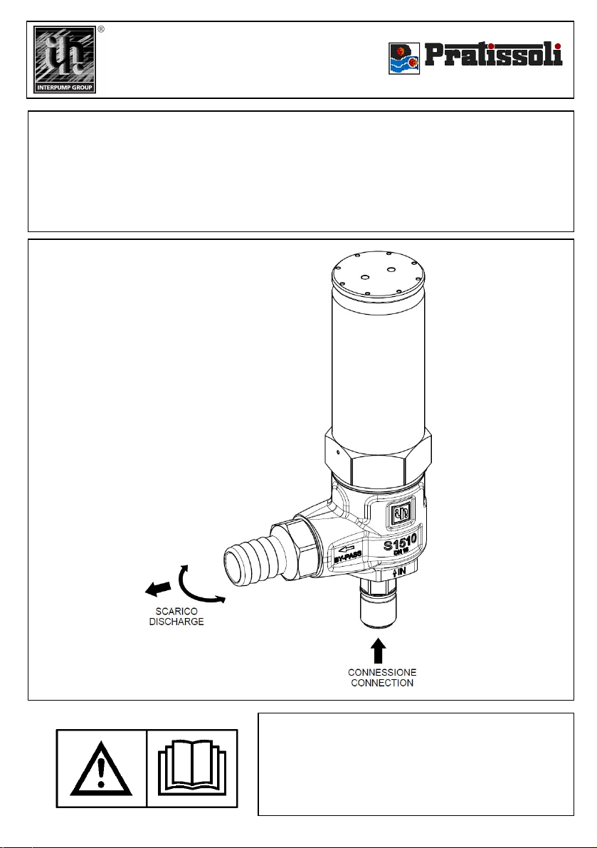
1.1- La soupape de limitation de la pression S1510 est
un dispositif à tarage manuel et actionné à la pression qui,
en fonction du réglage, évacue l’excédent d’eau quand la
pression à l’intérieur de la pompe/installation dépasse la
valeur de tarage, ainsi réduisant la pression. Le
rétablissement des conditions d’utilisation normales se
produit en arrêtant et ensuite en actionnant de nouveau
l’installation.
1.2- Puisque la soupape S1510 est utilisée avec une
pompe/installation pour eau à haute pression, qu’on
appellera ci de suite seulement «installation », la mise en
place et l’utilisation doivent être appropriées au type
d’installation utilisé et se conformer aux normes de sécurité
en vigueur dans le pays où la soupape est utilisée.
1.3- Avant d’utiliser la soupape, s’assurer que l’installation
avec laquelle celle-ci est utilisée a été déclarée conforme
aux dispositions des Directives et/ou normes relatives.
1.4- Avant d’installer et d’utiliser la soupape pour la
première fois, on conseille de contrôler que celle-ci n’est
pas endommagée et de vérifier que les caractéristiques
nominales correspondent à celles d’utilisation. Dans le cas
contraire, n’utilisez pas la soupape et contactez le service
après-vente de Interpump Group pour avoir des
renseignements.
2- EMBALLAGE
2.1- Effectuer la manutention des emballages en respectant
les instructions indiquées sur les emballages mêmes et/ou
fournies par le constructeur.
2.2- Au cas où la soupape n’est pas utilisée
immédiatement, il faut la stocker dans son emballage
intégral et la ranger à l’abri des intempéries, de l’humidité
excessive et de la lumière directe du soleil. Il est
conseillable aussi d’interposer des palettes en bois ou autre
matériel entre le sol et l’emballage, afin d’éviter le contact
direct avec le sol.
2.3- Éliminer les parties de l’emballage conformément aux
dispositions des lois en vigueur.
3- INSTRUCTIONS POUR L’INSTALLATION :
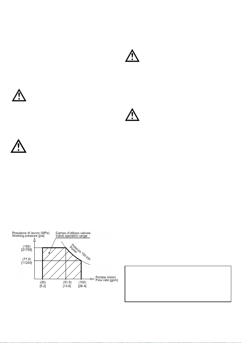
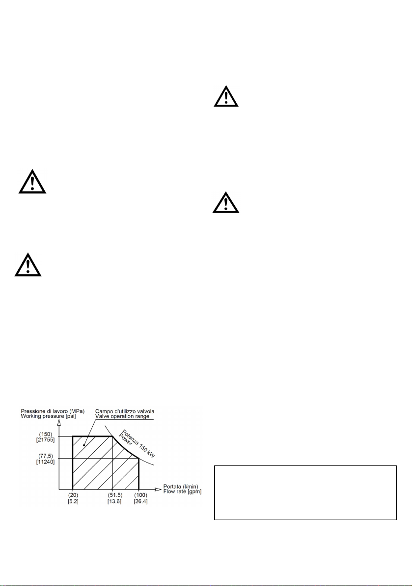
3.1- La pression de tarage SP est réglée et fixée par
scellement par Interpump Group et ne peut pas être
changée. Les valeurs de la pression de tarage et de la
pression maximum de fonctionnement conseillée WP
sont indiqués sur la soupape.
3.2- Le débit maximum dépend de la pression de tarage et
est compris entre 51.5 et 100 l/min. La valeur exacte est
indiquée sur la soupape.
3.3- La pression de tarage SP est la pression à la quelle la
soupape s’ouvre, qui correspond à la valeur maximum de
pression que l’installation peut atteindre.
3.4- L’installation doit être effectuée par un personnel
qualifié et autorisé, ayant la compétence nécessaire pour
travailler à des installations à haute pression et qui aient
connaissance des instructions d’utilisation et de sécurité
indiquées dans ce mode d’emploi.
3.5- Le système de fixation et d’étanchéité de la soupape
S1510 est conçu pour des pompes et/ou des produits
Interpump Group.
3.6- L’étanchéité du raccord G1/2 se produit par la pastille
conique code 083200210.
3.7- Avant d’installer la soupape, graisser un peu le filet
G1/2 avec de la graisse spécifique pour de très hautes
pressions EP (extreme pressure) contenant du Graphite ou
du Molybdène, ensuite serrer le raccord au moyen d’une clé
dynamométrique (70 Nm).
ATTENTION: Pendant l’utilisation, ne jamais
dépasser les valeurs maximums de pression,
débit et température indiquées dans le mode
d’emploi et/ou sur la soupape.
ATTENTION: Pour une utilisation correcte de
la soupape, il faut installer celle-ci dans le
secteur de l’installation qui atteint la pression
la plus haute pendant l’utilisation. De plus, on
conseille de la placer près de la pièce qui doit
être protégée le plus des pics de pression.
= FRANÇAIS =
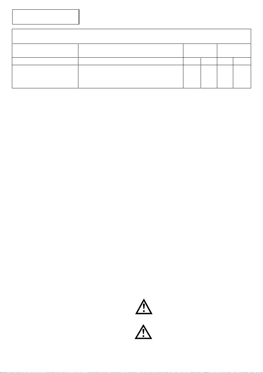
CARACTÉRISTIQUES TECHNIQUES
DÉBIT DOMAINE DE LA PRESSION DE
TARAGE
TEMP.
Max. MASSE
min - max min - max °C °F kg lbs
20 –100
5,2–26,4
l/min
g.p.m.
(USA)
48 –180
480 –1800
6960 –26105
MPa
bar
p.s.i.
30 70 2,7 5,95

- 10 -
4- PRÉCAUTIONS D’EMPLOI
4.1- L’installateur a la responsabilité de donner les
instructions adéquates à l’Utilisateur final pour l’utilisation
correcte de l’installation sur laquelle la soupape est
installée.
4.2- Pour relier la soupape à l’installation, utiliser des
raccords convenablement dimensionnés aux performances
de la soupape même.
4.3- Utiliser uniquement de l’eau douce et filtrée. L’emploi
d’eau salée et/ou contenant des particules solides ayant
des dimensions supérieures à 20µm cause une usure
rapide des parties internes de la soupape et en compromet
le bon fonctionnement. Des additifs comme des détergents
délicates, biodégradables et en tous cas conformes aux
normes en vigueur dans le Pays d’utilisation, peuvent être
ajoutés à l’eau utilisée.
4.4- Dans les installations pour la production
d’eau chaude, la température du liquide qui est
en contact avec la soupape doit être toujours
inférieure à la valeur indiquée dans le mode
d’emploi et/ou sur la soupape même. Eviter la
formation de vapeur ou d’eau surchauffée.
4.5- Avant d’utiliser l’installation, on conseille d’effectuer
préalablement une mise en marche d’essai pour vérifier que
l’équipement est correctement installé.
4.6- ATTENTION: Ne pas obstruer ni couvrir en
aucune façon la zone d’évacuation de l’eau de
la soupape. Ne pas essayer de canaliser l’eau,
mais déverser toujours dans l’atmosphère. Le
non respect de ces instructions très simples
signifierait compromettre la sûreté de
l’installation.
4.7- Afin d’optimiser l’accouplement pompe-soupape, il faut
limiter le domaine d’utilisation de la soupape en fonction de
la pression et du débit de la pompe, à la puissance
maximum de 150 kW (201 HP). Cela signifie utiliser des
pompes, comme indiqué dans le graphique, qui produisent
un débit d’environ 51.5 l/min. pour des pressions
maximums de fonctionnement de 150MPa (1500bar-
21755psi) et qui produisent une pression d’environ 77.5
MPa (775 bar –11240 psi) pour des débits maximums de
100 l/min.
4.8- Au cas où la soupape de limitation de la pression
s’ouvre, arrêter l’installation et rechercher la cause de la
hausse de pression.
5- ENTRETIEN
5.1- L’entretien et/ou la réparation doivent être effectués
seulement par Interpump Group.
5.2- On conseille, du moins tous les 2 ans ou
quand on atteint les 500 heures de
fonctionnement de l’installation, de contrôler
que la soupape s’ouvre régulièrement pour
vérifier la correspondance avec la pression de
tarage.
5.3- La soupape est produite entièrement avec des
matériaux non toxiques ni dangereux. De toute façon, en
cas d’élimination, on conseille de ne pas la disperser dans
l’environnement mais de la remettre à un centre de récolte
autorisé ou de s’adresser au Centre Après-vente Autorisé
INTERPUMP GROUP plus proche.
ATTENTION : Ne jamais altérer la soupape
et/ou l’utiliser pour des fonctions différentes
de celles pour lesquelles la soupape a été
produite.
En cas contraire, le constructeur décline toute
responsabilité sur le fonctionnement et la
sécurité de la soupape même.
6- CONDITIONS DE GARANTIE
6.1- La période et les conditions de la garantie sont
indiquées dans le contrat d’achat.
6.2- La garantie perd de validité dans le cas où la soupape
est utilisée improprement, faite fonctionner à des
performances supérieures à celles déclarées, réparée avec
des pièces non originales ou si celle-ci se révèle
endommagée à cause du non respect des instructions
d’utilisation ou à cause d’altérations non autorisées.
Les informations contenues dans ce manuel peuvent être changées sans
préavis.
Copyright
Le contenu de ce mode d’emploi est propriété de Interpump Group.
Les instructions contiennent des descriptions techniques et des
illustrations qui ne peuvent pas être copiées et/ou reproduites
entièrement ou en partie ni transmises à de tiers sous quelque forme que
ce soit et de toute façon sans l’autorisation par écrit du propriétaire.
Les transgresseurs seront poursuivis aux termes de la loi par des actions
appropriées.

- 11 -
«Übersetzung der Originalanleitung»
DIESES HANDBUCH ENTHÄLT DIE HINWEISE FÜR DIE
INSTALLATION, DIE BEDIENUNG UND DIE INSTAND-
HALTUNG DES VENTILS, ES IST SOMIT EIN FESTER
BESTANDTEIL DESSELBEN. DIE BEDIENUNGSANLEITUNG
VOR DEM GEBRAUCH AUFMERKSAM DURCHLESEN. DIE
BEDIENUNGSANLEITUNG SORGFÄLTIG AUFBEWAHREN.
FÜR EINEN SICHEREN UND EFFIZIENTEN EINSATZ DES
VENTILS DIE HINWEISE IN DER ANLEITUNG STRIKT
BEACHTEN.
WENN DIE ANLEITUNG NICHT BEFOLGT WIRD, KÖNNTEN
DARAUS GEFAHREN UND VORZEITIGE SCHÄDEN
ENTSTEHEN UND DIE GEWÄHRLEISTUNG DES
HERSTELLERS KÖNNTE UNWIRKSAM WERDEN.
1- ALLGEMEINE ANGABEN
1.1- Das Höchstdruckventil S1510 ist eine Vorrichtung mit
manueller Einstellung und Druckbetätigung. Sobald der Druck in
der Pumpe/ Anlage den Sollwert übersteigt, lässt es gemäß
seiner Einstellung das überschüssige Wasser ab und verringert
so den Druck. Die Wiederherstellung der normalen
Betriebsbedingungen erfolgt durch Ausschalten und Neustarten
der Anlage.
1.2- In Anbetracht der Tatsache, dass das Ventil S1510
zusammen mit einer Hochdruckwasserpumpe/ einer
Hochdruckanlage - im Folgenden kurz Anlage genannt -
eingesetzt wird, müssen Installation und Gebrauch der
Typologie der verwendeten Anlage angepasst werden und den
im Installationsland geltenden Sicherheitsbestimmungen
entsprechen.
1.3- Vor Gebrauch des Ventils stellen Sie sicher, ob die Anlage,
in der es eingebaut ist, mit den Bestimmungen der
entsprechenden Richtlinien und/oder Normen übereinstimmt.
1.4- Vor Installation und Gebrauch des Ventils empfehlen wir,
sich zu vergewissern, ob das Ventil unversehrt ist und die
technischen Daten auf dem Typenschild den Sollwerten
entsprechen. Anderenfalls verwenden Sie das Ventil nicht,
sondern setzen Sie sich mit dem Service Center von Interpump
Group für eventuelle Anweisungen in Verbindung.
2 –VERPACKUNG
2.1 –Die Packstücke müssen unter Beachtung der Angaben
gehandhabt werden, die auf den Packungen selbst angegeben
sind und/oder vom Hersteller geliefert wurden.
2.2 –Falls das Ventil nicht sofort verwendet wird , muâes in
unversehrter Verpackung in Bereichen gelagert wird, die vor
Witterung, zu hoher Feuchtigkeit und direkter
Sonneneinstrahlung geschützt ist. Auâerdem ist es zweckmäâig,
zwischen Boden und Packungen Paletten aus Holz oder einem
anderen Material zu legen, damit der direkte Kontakt mit dem
Boden verhindert wird.
2.3 –Das Verpackungsmaterial gemäâden einschlägigen
gesetzlichen Bestimmungen entsorgen.
3- INSTALLATIONSANLEITUNG:
3.1- Der Einstelldruck SP wird von Interpump Group
geregelt und per Versiegelung festgelegt; er kann nicht
verändert werden. Die Werte von Einstelldruck und
empfohlenem Höchstbetriebsdruck WP sind auf dem Ventil
angeführt.
3.2- Der Höchstdurchsatz hängt vom Einstelldruck ab und liegt
zwischen 51,5 und 100 l/min. Der genaue Wert ist auf dem Ventil
angeführt.
3.3- Der Einstelldruck SP ist der Druck, bei dem sich das Ventil
öffnet und so den Höchstwert des Drucks bestimmt, der in der
Anlage erreicht werden kann.
3.4- Die Installation ist von autorisiertem Fachpersonal
durchzuführen, das die nötigen Fachkenntnisse hat, um an
Hochdruckanlagen zu arbeiten, und das mit den Gebrauchs-
und Sicherheitsanweisungen in diesem Handbuch vertraut ist.
3.5- Das Befestigungs- und Dichtungssystem des Ventils S1510
ist für Pumpen und/oder Produkte von Interpump Group
ausgelegt.
3.6- Die Dichtung am Anschlussstück G1/2 erfolgt durch das
keilförmige Dichtungselement Code 083200210.
3.7 Vor der Installation des Ventils das Gewinde G1/2 mit
speziellem graphit- oder molybdänhaltigem Höchstdruckfett EP
(extreme pressure) leicht einfetten; danach das Anschlussstück
mit einem dynamometrischen Schlüssel auf 70 Nm anziehen.
VORSICHT: Während der Verwendung dürfen die
im Handbuch und/oder auf dem Ventil
angeführten Höchst werte für Druck, Durchsatz
und Temperatur auf keinen Fall überschritten
werden.
VORSICHT: Zur korrekten Verwendung muss
das Ventil in dem Anlagenbereich installiert
werden, der während der Verwendung den
höchsten Druck erreicht. Außerdem empfehlen
wir, es in der Nähe der Komponente zu
positionieren, die am meisten vor Druckspitzen
geschützt werden soll.
= DEUTSCH =
TECHNISCHE DATEN
FÖRDERLEISTUNG EINSTELLDRUCKBEREICH TEMP.
max GEWICHT
min - max min - max °C °F kg lbs
20 –100
5,2–26,4
l/min
g.p.m.
(USA)
48 –180
480 –1800
6960 –26105
MPa
bar
p.s.i.
30 70 2,7
5,95

- 12 -
4- HINWEISE FÜR DEN GEBRAUCH
4.1- Es ist Aufgabe des Installateurs, dem Endbenutzer die
notwendigen Anweisungen für den ordnungsgemäßen
Gebrauch der Anlage zu übergeben, in der das Ventil installiert
wird.
4.2- Um das Ventil an die Anlage anzuschließen
Anschlussstücke verwenden, die den Ventilleistungen
angemessen sind..
4.3- Es ist ausschließlich gefiltertes Süßwasser zu verwenden.
Bei Meerwasser und/oder Wasser mit über 20µm großen
Festkörpern kommt es zu einem raschen Verschleiß der
inneren Ventilelemente, was den korrekten Betrieb gefährden
kann. Man kann dem Wasser Zusatzstoffe wie nicht zu starke,
biologisch abbaubare Reinigungsmittel beigeben, die den im
Installationsland geltenden Gesetzesbestimmungen
entsprechen müssen.
4.4- In den Anlagen für die Heißwasser-
aufbereitung muss die Temperatur der Flüssigkeit,
die mit dem Ventil in Kontakt kommt, stets unter
dem Sollwert liegen, der im Handbuch und/oder
auf dem Ventil angegeben ist. Die Bildung von
Dampf oder überhitztem Wasser ist zu
vermeiden.
4.5- Vor Inbetriebnahme der Anlage empfehlen wir, die
ordnungsgemäße Installation der Geräte zu überprüfen und sie
dann das erste Mal zur Probe einzuschalten.
4.6- VORSICHT: Niemals darf der Bereich des zur
Ablass von Wasser bestimmten Ventils versperrt
oder abgedeckt werden. Versuchen Sie nicht das
abgelassene Wasser abzuleiten, sondern geben
Sie es immer in die Umwelt ab. Wenn diese
einfachen Hinweise nicht befolgt werden, kann
eine optimale Arbeitsweise des Ventils
beeinträchtigt werden. Die Nicht-beachtung
dieser Hinweise kann die Sicher-heit der Anlage
gefährden.
4.7- Zur Optimierung der Pumpen-Ventil-Kombination muss der
Einsatzbereich des Ventils je nach Pumpendruck und –
Durchsatz auf eine Höchstleistung von 150 kW (201 HP)
beschränkt werden. Das bedeutet –wie dies auf der
graphischen Darstellung zu sehen ist –dass Pumpen verwendet
werden müssen, die bei einem Höchstbetriebsdruck von 150
MPa (1500 Bar-21755 psi) einen Durchsatz von etwa 51,5 l/min
erzeugen, und bei einem Höchstdurchsatz von 100 l/min einen
Druck von etwa 77,5 Mpa (775 bar –11240 psi).
4.8- Sobald das Höchstdruckventil aktiviert wird, die Anlage
ausschalten und die Ursache des Druckanstiegs ermitteln.
5- INSTANDHALTUNG
5.1- Die Instandhaltung und die Reparaturen sind ausschließlich
von autorisiertem INTERPUMP GROUP Fachpersonal
vorzunehmen.
5.2- Es empfiehlt sich, mindestens alle 2 Jahre
bzw. bei Erreichen von 500 Betriebsstunden
eine Prüfung der Ventilfunktion vorzunehmen,
um die Entsprechung mit dem Einstelldruck
sicherzustellen.
5.3- Das Ventil wurde zur Gänze aus atoxischen bzw. nicht
schädlichen Werkstoffen hergestellt, wir empfehlen jedoch, im
Falle der Verschrottung darauf zu achten, dass es einer
zugelassenen Entsorgungsstelle übergeben wird oder wenden
Sie sich an das nächstgelegene Service Center von
INTERPUMP GROUP.
VORSICHT: Auf keinen Fall darf ein unerlaubter
Eingriff am Ventil vorgenommen und/oder das
Ventil für anderen Zwecken zugeführt werden
als den die vom Hersteller vorgesehenen
Zwecke verwendet werden. Andernfalls
übernimmt der Hersteller keine Haftung für den
Betrieb und die Sicherheit des Ventils.
6- GARANTIEBEDINGUNGEN
6.1- Die Garantiezeit und die Garantiebedingungen sind im
Kaufvertrag angeführt.
6.2- Die Garantie verfällt bei unsachgemäßer Handhabung des
Ventils oder wenn das Ventil für höhere Leistungen eingesetzt
wird als die angegebenen, bei Reparaturen mit Nicht-
Originalersatzteilen oder wenn Schäden durch die
Nichtbeachtung der Gebrauchsanweisung oder unerlaubte
Eingriffe durch nicht autorisierte Personen entstehen.
Die in diesem Handbuch enthaltenen Informationen können ohne Vorankündigung
geändert werden.
Copyright
Der Inhalt dieses Handbuchs ist Eigentum von Interpump Group.
Die Anleitung enthält technische Angaben sowie Bildmaterial, die weder
vollständig noch teilweise in irgendeiner Form ohne vorherige schriftliche
Genehmigung von Interpump Group kopiert bzw. vervielfältigt oder an
Dritte weitergegeben werden dürfen.
Zuwiderhandlungen werden gesetzlich verfolgt.

- 13 -
DICHIARAZIONE DI CONFORMITA’
(Ai sensi dell’allegato II della Direttiva Europea 2006/42/CE)
Il produttore INTERPUMP GROUP S.p.A. –Via E. Fermi, 25 –42049 S. ILARIO D’ENZA (RE) –Italia
DICHIARA che l’attrezzatura identificata e descritta come segue:
Denominazione: Accessorio a pressione
Tipo: Valvola di massima pressione
Marchio di fabbrica: INTERPUMP GROUP
Modello: S1510
Risulta essere conforme ai requisiti delle sotto elencate direttive e successivi aggiornamenti:
Direttiva Macchine 2006/42/CE
Direttiva 97/23/CE –PED (articolo 3 paragrafo 3)
Direttiva sulla restrizione dell’uso di determinate sostanze pericolose 2002/95/CE - RoHS
Direttiva sulla responsabilità del produttore 85/374/CE
UNI EN ISO 12100-1:2005 –UNI EN ISO 12100-2:2005 –UNI EN 14121-1:2007 –UNI EN ISO 12516-1:2005 –UNI EN
ISO 12516-2:2004
Persona autorizzata a costituire il fascicolo tecnico Nome: Maurizio Novelli
Indirizzo: INTERPUMP GROUP S.p.A. –Via E. Fermi, 25 –
42049 S. ILARIO D’ENZA (RE) –Italia
Persona autorizzata a redigere la dichiarazione: L’amministratore delegato Ing. Paolo Marinsek
Reggio Emilia 22/02/2010 Firma __________________________
DECLARATION OF CONFORMITY
(According to annex II of European Directive 2006/42/EC)
The manufacturer INTERPUMP GROUP S.p.A. –Via E. Fermi, 25 –42049 S. ILARIO D’ENZA (RE) –Italy
DECLARE that the device identified and described as follows:
Description: Pressure accessory
Type: Relief valve
Trademark: INTERPUMP GROUP
Model: SV12
Complies with the requirements of the below-listed directives and following updates:
Directive 2006/42/EC Machinery
Directive 97/23/EC –PED (article 3 paragraph 3)
Directive 2002/95/EC Reduction of hazardous substances - RoHS
Directive 85/374/EC Liability for defective products
UNI EN ISO 12100-1:2005 –UNI EN ISO 12100-2:2005 –UNI EN 14121-1:2007 –UNI EN ISO 12516-1:2005 –UNI EN
ISO 12516-2:2004
Person authorized to compile the technical documents Name: Maurizio Novelli
Address: INTERPUMP GROUP S.p.A. –Via E. Fermi, 25 –
42049 S. ILARIO D’ENZA (RE) –Italia
Person empowered to draw up the declaration: Ing. Paolo Marinsek (Managing Director)
Reggio Emilia 22/02/2010 Signature __________________________

- 14 -
DÉCLARATION DE CONFORMITE’
(Aux termes de la pièce annexe II de la Directive Européenne 2006/42/CE)
Le fabricant INTERPUMP GROUP S.p.A. –Via E. Fermi, 25 –42049 S. ILARIO D’ENZA (RE) –Italie
DÉCLARE que le dispositif identifié et décrit ci-après :
Description: Accessoire à pression
Type: Soupape de limitation de la pression
Marque de fabrique: INTERPUMP GROUP
Modèle: S1510
Est conforme aux normes des directives indiquées ci-après et aux suppléments successifs :
Directive 2006/42/CE relative aux machines
Directive 97/23/CE –PED (article 3 paragraphe 3)
Directive 2002/95/CE –RoHS relative à la limitation de l’utilisation de certaines substances dangereuses
Directive 85/374/CE en matière de responsabilité du fait des produits défectueux
UNI EN ISO 12100-1:2005 –UNI EN ISO 12100-2:2005 –UNI EN 14121-1:2007 –UNI EN ISO 12516-1:2005 –UNI EN
ISO 12516-2:2004
Personne autorisée à préparer le dossier technique Nom : Maurizio Novelli
Adresse : INTERPUMP GROUP S.p.A. –Via E. Fermi, 25 –
42049 S. ILARIO D’ENZA (RE) –Italia
Personne autorisée à rédiger la déclaration: Ing. Paolo Marinsek (Administrateur Délégué)
Reggio Emilia, le 22/02/2010 Signature __________________________
KONFORMITÄTSERKLÄRUNG
(gemäß Anhang II der Richtlinie 2006/42/EG)
Der Hersteller INTERPUMP GROUP S.p.A. –Via E. Fermi, 25 –42049 S. ILARIO D’ENZA (RE) –Italien
ERKLÄRT HIERMIT, dass die im Folgenden identifizierte und beschriebene Ausrüstung:
Bezeichnung: Druckvorrichtung
Type: Höchstdruckventil
Marke: INTERPUMP GROUP
Modell: S1510
den Anforderungen der unten angeführten Richtlinien und nachfolgenden Ergänzungen voll entspricht:
Maschinenrichtlinie 2006/42/EG
Richtlinie 97/23/EG –PED (Artikel 3 Absatz 3)
Richtlinie zur Beschränkung der Verwendung bestimmter gefährlicher Stoffe 2002/95/EG - RoHS
Richtlinie über die Haftung des Herstellers 85/374/EG
UNI EN ISO 12100-1:2005 –UNI EN ISO 12100-2:2005 –UNI EN 14121-1:2007 –UNI EN ISO 12516-1:2005 –UNI EN
ISO 12516-2:2004
Zur Zusammenstellung der technischen
Unterlagen ermächtigte Person Name: Maurizio Novelli
Adresse: INTERPUMP GROUP S.p.A. –Via E. Fermi, 25 –
42049 S. ILARIO D’ENZA (RE) –Italia
Zur Erstellung der Erklärung ermächtigte Person: Geschäftsführer Ing. Paolo Marinsek
Reggio Emilia 22/02/2010 Unterschrift __________________________

- 15 -
Table of contents
Languages:
Other Interpump Group Control Unit manuals
Popular Control Unit manuals by other brands

Wheelock
Wheelock NACIM installation instructions

Pioneer
Pioneer CX-961 Service manual

Comet
Comet CBM Series Instructions for assembly, operation and maintenance

Siemens
Siemens SINAMICS G120P CU230P-2 Compact operating instructions

Kaba Mauer
Kaba Mauer 82132 Mounting instructions

KIESELMANN
KIESELMANN 5093 xxx 000 series operating instructions