VIRPIL VPC MongoosT-50 Base User manual

VPC MongoosT-50® Base
Quick Start Guide
Version 1.4 - 09/2017

VPC MONGOOST-50® BASE
QUICK START GUIDE
INTRODUCTION
This quick start guide is intended to be used to get you started with the basics of the VPC
MongoosT-50® Base. An in-depth user manual will be provided at a later date.
SPECIFICATION
Grip Interface: Mini DIN 5 Pin
PC Interface: USB 2.0
Number of Axis: 2
Samples per Axis: >4864
Minimum Detected Deflection: 0.006°
Max Axis Deflection: 30° (± 15° from central position)
Stroke Length with VPC MongoosT-50® Grip: 150mm (± 5mm)
Max Force per Axis: 3.5kg
Base Dimension - without Stem (L x W x D): 85 mm x 83 mm x 130 mm
Stem Height: 50mm
Weight: 1.1kg
*Note: Compatible Grips:
●VPC MongoosT-50® Grip
●VPC MongoosT-50® BE Grip
●VPC MongoosT-50® LH Grip
●Thrustmaster® HOTAS Warthog™ Grip
●Thrustmaster® HOTAS Cougar™ Grip
WHAT’S INCLUDED
Included with the VPC MongoosT-50® Base:
●VPC MongoosT-50® Base
●Axis Cams
○2 x Hard Center Cams
○2 x Soft Center Cams
○2 x No Center Cams
●Axis Compression Springs
○2 x Light Springs
○2 x Medium Springs
○2 x Heavy Springs
●U-Bracket Mount
●User Manual
●Packing Slip
●Warranty Card
●Packaging
2

VPC MONGOOST-50® BASE
QUICK START GUIDE
VPC MONGOOST-50® BASE
FIGURE 1
1. 4 x M4 Screws - Affixing upper plate to base exterior.
2. U-Bracket for attaching to the VPC Desk Mount or other mouthing method.
3. 4 x M4 Screws - Affixing upper plate to gimbal structure.
4. Grip stem with screw-thread connector and Mini DIN 5 Pin connector.
5. Rubber boot for dust protection.
6. Access port for adjusting the “Pitch” (Y) axis loading force.
7. Access port for adjusting the “Roll” (X) axis loading force.
8. 5 x M3 Screws - Affixing rubber boot to upper plate.
9. Base exterior housing.
10. Upper plate.
11. 4 x M5 Screws - Affixing U-Bracket to base exterior and gimbal structure.
12. 4 x M5 Screws - Affixing U-Bracket to VPC Desk Mount or other mounting solution.
13. 4 x M4 Screws - Affixing lower plate to base exterior.
14. Lower plate.
15. USB 2.0 cable.
3

VPC MONGOOST-50® BASE
QUICK START GUIDE
VPC MONGOOST-50® GIMBAL
FIGURE 2
1. Roll axis lever bearing
2. Roll axis lever arm
3. Pitch axis tension adjustment screw (with compression spring)
4. Roll axis tension adjustment screw (with compression spring)
5. Pitch axis cam
6. Pitch axis lever arm
7. Gimbal mechanics structure
8. Pitch axis lever bearing
9. Roll axis cam bearing (same for Pitch axis)
10. 2 x M3 Roll axis cam mounting screws (same for Pitch axis)
11. Roll axis cam
12. Grip stem bearing
13. Upper plate
4

VPC MONGOOST-50® BASE
QUICK START GUIDE
VPC MONGOOST-50® CAMS
Hard Center Cam Soft Center Cam No Center Cam
VPC MONGOOST-50® SPRINGS
Light Spring Medium Spring Heavy Spring
5

VPC MONGOOST-50® BASE
QUICK START GUIDE
BASIC OPERATION
●The VPC MongoosT-50® Base is compatible with the VPC Extensions. Extensions up to
150mm are supported, extensions larger than this are not recommended, especially when
combined with heavier springs.
●The VPC MongoosT-50® Base should be mounted with the included VPC U-Bracket. If this is
unsuitable, a custom mount can be created to connect directly to the existing 4 x VPC
U-Bracket mounting points. Different length screws should be used to account for the
difference between the original VPC U-Bracket and any custom solution. It is not
recommended to mount the base via the underside bolts. Any damage caused by a custom
mounting solution is not covered by the standard warranty.
●When adjusting the spring loading screws via the upper plate adjustment holes the minimum
allowed tension is when half of the joysticks deflection is free of any spring force. The
maximum allowed tension is achieved by roughly 25 clockwise turns. Over tensioning the
spring loading screws can result in the joysticks total deflection being limited. If you require
stronger spring tension, replace the axis compression springs for the heavier set.
●The VPC MongoosT-50® Base is a complex piece of equipment aimed at the experienced
user. Replacing the springs and cams can be a complicated process and if you are at all
unsure, please contact VPC directly for help to avoid damage to your set. User damage while
attempting to make adjustments to the base is not covered by the manufacturer warranty
and would be subject to a repair cost.
REPLACING THE AXIS COMPRESSION SPRINGS
1. Disconnect the base USB cable from the PC.
2. Remove the base from the VPC Desk Mount or other mounting method.
3. Remove the attached grip from the base.
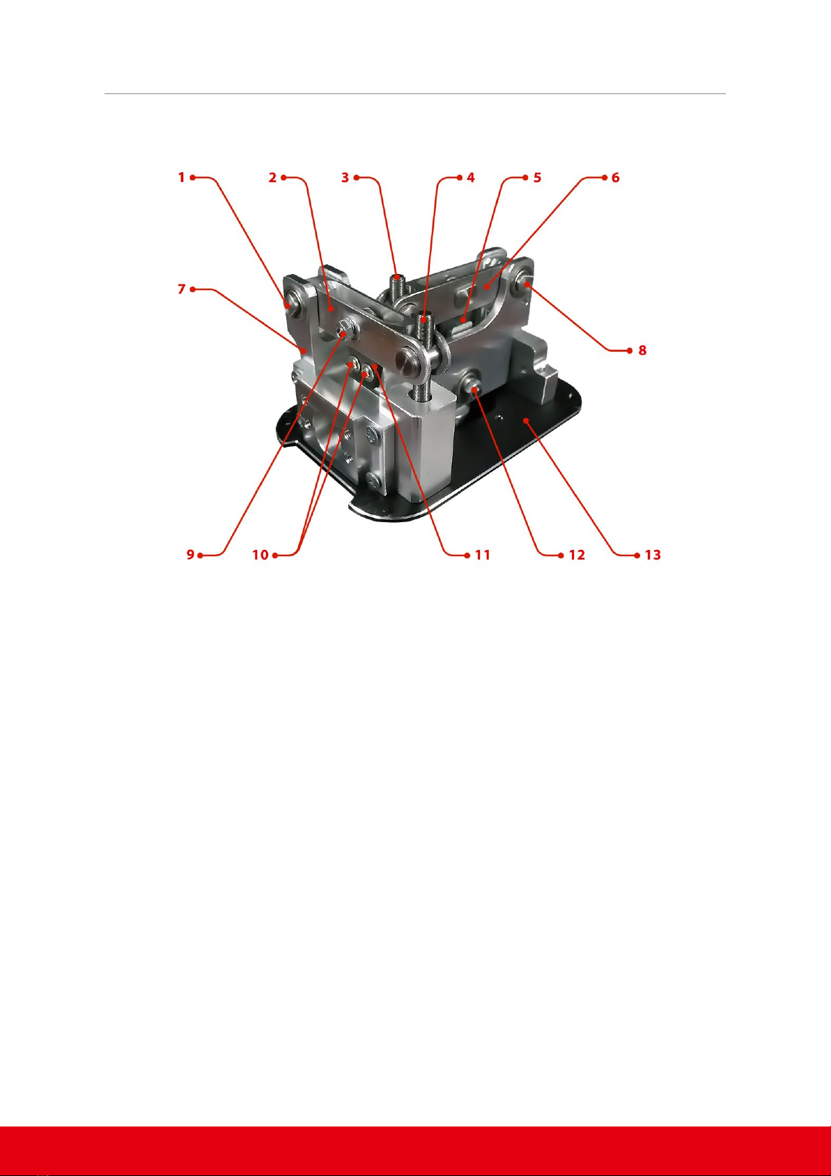
4. Loosen the spring loading tension on the Pitch (FIGURE 1 - #6) and Roll (FIGURE 1 - #7) axes via
the adjustment holes on the upper plate.
5. Remove the 4 x M4 screws from the lower plate (FIGURE 1 - #13). Store the lower plate in a
safe location to avoid damage.
6. Remove the 4 x M4 screws from the upper plate (FIGURE 1 - #1).
7. Remove 5 x M3 screws affixing the rubber boot surround to the upper plate.
8. Remove the 4 x M4 screws affixing the upper plate to the gimbal structure (FIGURE 1 - #3).
9. Completely remove the rubber boot (FIGURE 1 - #5) and upper plate (FIGURE 1 - #10) over the
grip stem (FIGURE 1 - #4).
10. Completely loosen the spring loading screw for the axis you wish to replace the spring on.
While you do this, hold the cylindrical nut from the lower side of the base.
11. With the spring loading screw completely loosened, remove it from the gimbal and you will
be able to remove the currently equipped spring. Replace the spring with your desired
choice.
12. Place the spring loading screw with the newly equipped compression spring, back into its
recess.
13. While holding the cylindrical nut from the lower side of the base, hand tighten the screw
until the spring starts to become loaded.
14. Reassemble the base by repeating the steps in reverse from step 9.
6

VPC MONGOOST-50® BASE
QUICK START GUIDE
15. Fine tune the spring tension using the Pitch (FIGURE 1 - #6) and Roll (FIGURE 1 - #7) axes
adjustment holes on the upper plate.
REPLACING THE AXIS CAMS
1. Disconnect the base USB cable from the PC.
2. Remove the base from the VPC Desk Mount or other mounting method.
3. Remove the attached grip from the base.
4. Loosen the spring loading tension on the Pitch and Roll axes via the adjustment holes on the
upper plate.
5. Remove the 4 x M4 screws from the lower plate (FIGURE 1 - #13). Store the lower plate in a
safe location to avoid damage.
6. Remove the 4 x M4 screws from the upper plate (FIGURE 1 - #1).
7. Remove the 4 x M5 screws affixing the U-Bracket to base exterior and gimbal structure.
8. Remove 2 x M3 screws on the front side of the base, affixing the VPC-Controller board to the
interior of the base housing. NOTE: Pay attention to the spacers used for mounting the
VPC-Controller board.
9. Carefully lift the gimbal and electronics from out of the base housing, being sure not to
damage the electronics or wiring.
10. Completely loosen the spring loading screw for the axis you wish to replace the spring on.
While you do this, hold the cylindrical nut from the lower side of the base.
11. When the spring loading screw is removed from the cylindrical nut, open the lever axis arm
(FIGURE 2 - #2 #6) to access the cam.
12. Remove the 2 x M3 cam mounting screws (FIGURE 2 - #10).
13. Remove the existing cam (FIGURE 2 - #5, #11) from the gimbal and replace with your desired
cam. NOTE: Removing the cams for the first few times can require additional effort,
especially the pitch cam. To help remove the pitch cam (FIGURE 2 - #5) you can rock the cam
side to side to ease it out of the cam slot.
14. With the new cam installed, complete the reassembly of the base by following the steps
back in reverse from step 15.
7
Table of contents
Popular Control Unit manuals by other brands

Grohe
Grohe GROHSAFE 3.0 35 11 Series owner's manual

Watts
Watts HKF20 Series Installation and operating manual

Siemens
Siemens SINAMICS S110 Getting started

Microchip Technology
Microchip Technology maXTouch Curiosity Pro user guide

Berbel
Berbel AutoRun installation instructions

Minarik
Minarik SL10U user manual

Nice
Nice UDL 1 Instructions and information for installation and use

VXI
VXI VT1419A Multifunction Plus user manual

schmersal
schmersal SRB 202MSL operating instructions

salmson
salmson Siriux DP-BUS Installation and operating instructions

Bentel Security
Bentel Security KYO 4 M user manual

HETRONIC
HETRONIC CSM2400FH user manual