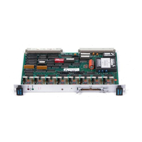
Xycom XVME-977 User manual

XVME-977
Hard Disk/Floppy Disk
Module
P/N 74977-001A
© 1996 XYCOM, INC. XYCOM
750 North Maple Road
Printed in the United States of America Saline, Michigan 48176-1292
Part Number 74977-001A (313) 429-4971

Xycom Revision Record
Revision Description Date
A Manual Released 4/96
Trademark Information
Brand or product names are registered trademarks of their respective owners.
Copyright Information
This document is copyrighted by Xycom Incorporated (Xycom) and shall not be reproduced or copied without
expressed written authorization from Xycom.
The information contained within this document is subject to change without notice. Xycom does not guarantee the
accuracy of the information and makes no commitment to keeping it up to date.
Address comments concerning this manual
to:
xycom
Technical Publications Department
750 North Maple Road
Saline, MI 48176-1292
Part Number: 74977-001A

Table of Contents
Chapter 1 – Introduction
Module Features .....................................................................................................................................1-1
Specifications..........................................................................................................................................1-1
Hardware Specifications......................................................................................................................1-2
Environmental Specifications ..............................................................................................................1-2
Chapter 2 – Installation
Installing into a VMEbus Card Cage .......................................................................................................2-1
Configuring the XVME-977 .....................................................................................................................2-3
VMEbus Interface ...................................................................................................................................2-4
Pinouts ....................................................................................................................................................2-4
P1 Connector ......................................................................................................................................2-4
P2 Connector ......................................................................................................................................2-5
Floppy Drive Connector (P3) ...............................................................................................................2-6
Hard Drive Connector (P4)..................................................................................................................2-6


1-1
Chapter 1 – Introduction
The XVME-977 Hard Disk/Floppy Disk Module provides an easy way to integrate both
hard and floppy disk drives into a VMEbus system. Constructed for the industrial mar-
ket, where high levels of shock and vibration are the norm, the module is a single-slot
VME form factor disk drive with a 3.5-inch floppy drive and a 2.5-inch hard drive.
Compact and easy to install, the XVME-977 Hard Disk/Floppy Disk Module is an ideal
mass storage solution for a variety of VMEbus systems. This module is built to commu-
nicate with Xycom’s XVME-65x VMEbus PC/AT processors.
Power for the XVME-977 is provided by the P1 and P2 connectors. Signals are routed
through P2. Figure 1-1 illustrates this in a block diagram of the XVME-977.
P2 Connector
Floppy Drive
(26pin FFC conn.)
Hard Drive
(50pin 2mm RTA conn.)
Figure 1-1. XVME-977 Block Diagram
Module Features
The XVME-977 Hard Disk/Floppy Disk Module offers the following features:
•Occupies one VMEbus slot
•Hard drive activity LED
•Needs only +5V
•IDE hard drive
•3.5-inch, 1.44 Mbyte high-density floppy drive
Specifications
This section contains the hardware and environmental specifications for the XVME-977.

XVME-977 Hard Disk/Floppy Disk Module Manual
1-2
Hardware Specifications
Hard Drive
Table 1-1 provides the hardware specifications for the hard drive.
Table 1-1. Hard Drive Hardware Specifications
Characteristic Specification
Interface IDE
Type 2.5 inch
Floppy Drive
Table 1-2 provides the hardware specifications for the floppy drive.
Table 1-2. Floppy Drive Hardware Specifications
Characteristic Specification
Interface PC/AT-compatible
Compatibility 3.5", 1.44 Mbyte
Environmental Specifications
Table 1-3 provides the environmental specifications for the XVME-977.
Table 1-3. Environmental Specifications
Characteristic Specification
Temperature
Operating
Non-operating
0° to 50° C (0° to 122° F)
-40° to 60° C (-40° to 140° F)
Humidity 20 to 80% RH, non-condensing
Vibration
Operating
Non-operating
0.5g, 0-500 Hz
1g, 10-100 Hz
Shock
Operating
Non-operating
5 g peak acceleration, 11 msec duration
50 g peak acceleration, 11 msec duration
Current
Hard drive
Floppy drive
1140 mA peak; 520 mA average active
800 mA peak; 290 mA average active

2-1
Chapter 2 – Installation
This chapter describes how to install the XVME-977 Hard Disk/Floppy Disk Module
into the VMEbus backplane. It also provides information on connecting the XVME-977
to Xycom’s XVME-65x VMEbus PC/AT processor modules.
Installing into a VMEbus Card Cage
The XVME-977 occupies only one double-high VMEbus slot, and fits into any standard
6U VMEbus card cage. Like all of Xycom’s modules, the XVME-977 is designed to
comply with all electrical VMEbus backplane specifications. This module only draws
current from the +5 volt power supply.
Caution
Never attempt to install or remove any boards before turning
off power to the bus and all related external power supplies.
Before installing a module, determine and verify all connec-
tions to external devices or power supplies.
Figure Chapter 2 -1 depicts installation of the XVME-977 board.

XVME-977 Hard Disk/Floppy Disk Module
2-2
Figure Chapter 2 -1. XVME-977 Installation

Chapter 2 – Installation
2-3
To install the XVME-977 in a card cage…
1. Turn off power to the chassis.
2. Connect the jumper cable from the CPU slot to the XVME-977 slot on the rear of the
P2 backplane, as shown in Figure Chapter 2 -1.
Technical Note
It should not be necessary to use excessive force or pressure
to engage the connectors. If the board does not connect prop-
erly with the backplane, remove the module and inspect all
connectors and guide slots for possible damage or obstruc-
tions.
3. Apply straightforward pressure to the handles on the front of the panel, until the
connectors are fully engaged and properly seated.
4. Once the board is properly seated, secure it to the chassis by tightening the machine
screws at the top and bottom of the XVME-977 board.
5. Turn on power to the unit.
Configuring the XVME-977
To set floppy and hard drive specifications…
1. Turn on power to the unit.
2. Press F2 to enter the Main Setup menu.
3. Using the arrow keys, move down the screen to the Diskette A: option and set it as
follows:
Diskette A: [1.44 MB, 3½"]
Diskette B: [Not Installed]
4. Move to the IDE Adapter 0 Master option, and press ENTER to display the IDE
Adapter Sub-menu.
5. Press ENTER to auto-configure the hard drive, or type in specific parameters. Use the
information printed on the label affixed to the hard drive. An example of the label in-
formation is shown below:
FIXED DISK:0 TYPE: USER CY920 HD10 ST17 LZ920 WP0
6. Press ESC after all changes have been made.
7. Once the specifications have been set, reboot the system. The operating system can
now be loaded. The hard drive is preformatted with a 1:1 interleave, so low-level
formatting is not required.
Installation and configuration of the XVME-977 is now complete.
XVME-977 Hard Disk/Floppy Disk Module
2-4
VMEbus Interface
The VMEbus connector provides power (+5 V and GND). The bus grant in and bus grant
out are connected together, and the IACKIN* and IACKOUT* are connected together.
Pinouts
This section describes the pinouts for each of the four connectors on the XVME-977.
P1 Connector
Pin A B C
1NC NC NC
2NC NC NC
3NC NC NC
4NC BG0IN* NC
5 NC BG0OUT* NC
6NC BG1IN* NC
7 NC BG1OUT* NC
8NC BG2IN* NC
9 GND BG2OUT* GND
10 NC BG3IN* NC
11 GND BG3OUT* NC
12 NC NC NC
13 NC NC NC
14 NC NC NC
15 GND NC NC
16 NC NC NC
17 GND NC NC
18 NC NC NC
19 GND NC NC
20 NC GND NC
21 IACKIN* NC NC
22 IACKOUT* NC NC
23 NC GND NC
24 NC NC NC
25 NC NC NC
26 NC NC NC
27 NC NC NC
28 NC NC NC
29 NC NC NC
30 NC NC NC
31 NC NC NC
32 +5V +5V +5V

Chapter 2 – Installation
2-5
P2 Connector
Pin A B C
1 RES (NC) +5V HDRESET*
2 RES (NC) GND HD0
3 RES (NC) RES (NC) HD1
4 RES (NC) RES (NC) HD2
5 RES (NC) RES (NC) HD3
6 RES (NC) RES (NC) HD4
7 RES (NC) RES (NC) HD5
8 RES (NC) RES (NC) HD6
9 RES (NC) RES (NC) HD7
10 RES (NC) RES (NC) HD8
11 RES (NC) RES (NC) HD9
12 RES (NC) GND HD10
13 RES (NC) +5V HD11
14 RES (NC) RES (NC) HD12
15 RES (NC) RES (NC) HD13
16 RES (NC) RES (NC) HD14
17 RES (NC) RES (NC) HD15
18 RES (NC) RES (NC) GND
19 GND RES (NC) DIOW*
20 RES (nc) RES (NC) DIOR*
21 IDX* RES (NC) IORDY
22 MO1* GND ALE
23 HDRQ RES (NC) IRQ14
24 FDS1* RES (NC) IOCS16*
25 HDACK* RES (NC) DA0
26 FDIRC* RES (NC) DA1
27 FSTEP* RES (NC) DA2
28 FWD* RES (NC) CS1P*
29 FWE* RES (NC) CS3P*
30 FTK0* RES (NC) IDEATP*
31 FWP* GND FHS*
32 FRDD* +5V DCHG*

XVME-977 Hard Disk/Floppy Disk Module
2-6
Floppy Drive Connector (P3)
Pin Si
g
nal Pin Si
g
nal
1 +5V 14 FSTEP*
2 IDX* 15 GND
3 +5V 16 FWD*
4 FDS1* 17 GND
5 +5V 18 FWE*
6 DCHG* 19 GND
7 NC 20 FTK0*
8NC 21GND
9NC 22FWP*
10 MO1* 23 GND
11 NC 24 FRDD*
12 FDIRC* 25 GND
13 NC 26 FHS*
Hard Drive Connector (P4)
Pin Si
g
nal Pin Si
g
nal
1NC 26NC
2 NC 27 HDRQ
3NC 28GND
4NC 29DIOW*
5NC 30GND
6NC 31DIOR*
7 HDRESET* 32 GND
8GND 33IORDY
9HD7 34ALE
10 HD8 35 HDACK*
11 HD6 36 GND
12 HD9 37 IRQ14
13 HD5 38 IOCS16*
14 HD10 39 DA1
15 HD4 40 NC
16 HD11 41 DA0
17 HD3 42 DA2
18 HD12 43 CS1P*
19 HD2 44 CS3P*
20 HD13 45 IDEATP*
21 HD1 46 GND
22 HD14 47 +5V
23 HD0 48 +5V
24 HD15 49 GND
25 GND 50 NC

Index-1
Index
B
block diagram, 1-1
C
card cage installation, 2-1
connectors
floppy drive, 2-6
hard drive, 2-6
P1, 2-4
P2, 2-5
E
environmental specifications, 1-2
F
features, module, 1-1
floppy drive
connector, 2-6
hardware specifications, 1-2
specifications, setting, 2-3
H
hard drive
connector, 2-6
hardware specifications, 1-2
specifications, setting, 2-3
I
installation, card cage, 2-1
interface, VMEbus, 2-4
M
module features, 1-1
P
P1 connector, 2-4
P2 connector, 2-5
S
specifications
environmental, 1-2
hardware
floppy drive, 1-2
hard drive, 1-2
V
VMEbus interface, 2-4
Table of contents
Other Xycom Control Unit manuals

Xycom
Xycom XVME-675 User manual

Xycom
Xycom XVME-100 User manual

Xycom
Xycom XVME-530 User manual

Xycom
Xycom XVME-678 User manual

Xycom
Xycom XVME-682 User manual

Xycom
Xycom XVME-601 User manual

Xycom
Xycom XVME-678 User manual

Xycom
Xycom XVME-653 User manual

Xycom
Xycom XVME-956 Series User manual

Xycom
Xycom XVME-951 User manual