Interpump Group W101 User manual


INTERPUMPGROUP
1.131.914.57.3510.017502900202005.5521W922
1.131.914.54.045.517501450101005.5521W914
1.131.914.55.517.514502320161604.7518WS162
31.9
30.8
31.9
31.9
30.8
31.9
31.9
31.9
30.8
31.9
30.8
31.9
31.9
31.9
30.8
31.9
30.8
31.9
31.9
30.8
31.9
31.9
31.9
30.8
Ibs
1.014.02.944.014501450101003.9615WS101
1.014.03.675.017501885131303.9615W913
1.114.55.517.514502900202003.9615WS201
1.014.02.944.014501750121203.4313WS133
1.114.58.0811.01750400027.52753.9615
W928
T9281
1.114.55.517.517502900202003.9615W921
1.114.54.045.514502175151503.9615WS151
1.114.54.045.514501885131303.9615WS131
1.114.54.045.514502465171703.4313WS171
1.114.55.517.510002900202003.9615W201
1.114.54.045.510002175151503.9615W151
1.114.54.045.510001885131303.9615W131
1.014.02.944.010001450101003.9615W101
1.114.57.3510.014502900202005.5521WS202
1.114.55.517.514502175151505.5521WS152
1.114.54.045.514501450101005.5521WS102
1.114.55.517.510002320161604.7518W162
1.114.55.517.517502320161604.7518W916
1000
1450
1.014.03.675.017501450101004.7518W912
1.014.02.944.0145011608805.5521WS82
1.114.54.045.514501750121204.9418.7WS132
kW Lt.
1000
1.014.02.944.013009904.7518WS92
1.114.54.045.51885131304.7518W132
1.0
Kg
2.944.0
Hp
Potenza
Power
Puissance
Leistung
Potencia
Poder
14.0
psiMPabargpmL/min
13009904.7518W92
Peso
Weight
Poids
Gewicht
Peso
Peso
g/m
rpm
t/m
upm
r/m
r/m
Pressione
Pressure
Pression
Druck
Presión
Pressão
Portata
Flow rate
Débit
Förderstrom
Caudal
Fluxo
Modello
Model
Modèle
Modell
Modelo
Modelo
S
E
R
I
E
S
47
D
E
P
I
GB
F
ISTRUZIONI D’USO
INSTRUCTIONS FOR USE
MODE D’EMPLOI
BEDIENUNGSANLEITUNG
INSTRUCCIONES DE USO
INSTRUÇÕES DE USO
Questo manuale deve essere letto e compreso in accordo al libretto generico “Istruzioni d’uso e manutenzione”.
This manual must be read and followed in accordance with the generic “Instructions for Use and Maintenance”booklet.
Ce manuel doit être lu et compris en accord avec la notice générale “Mode d’emploi et d’entretien ”.
Dieses Handbuch ist in Verbindung mit dem allgemeinen Handbuch “Gebrauchs- und Wartungsanleitung“zu lesen und zu verstehen.
Este manual debe leerse y comprenderse de acuerdo con el manual general “Instrucciones de uso y mantenimiento”
Este manual deve ser lido e interpretado de acordo com o livro genérico “Instruções de uso e manutenção”

DIS. COD. 47.9524.00
* Fissare con Loctite 542 col. ROSSO
* Affix with Loctite 542 col. RED
* Fixer avec de la Loctite 542 couleur ROUGE
* Mit Loctite 542 ROT befestigen
* Fijar con Loctite 542 col. ROJO
* Fixar com Loctite 542 cor. VERMELHA
1

1
1
Carter
Carter - WS152-WS202-W921
47.0100.22
47.0102.22
18
3Boccola Ø 22x25x3090.9126.0017
1Coperchio cuscinetto47.1511.2213
3Anello rad. Ø 22x32x2.5 290.1625.0016
6Sede valvola 136.2003.665
6Valvola 136.2001.766
6Guida valvola 136.2002.518
6OR Ø 20.24x2.62 (3081) 4-590.3847.009
6
6
Tappo M24x2x16.5 4
Tappo M24x2x16.5 - NICKEL 5
98.2220.00
98.2222.00
10
6Gruppo valvola 136.7032.0111
8Vite M8x16 UNI 593199.3039.0012
2OR Ø 67.95x2.62 (3325)90.3913.0014
6Molla Ø 9.4x14.8 194.7376.007
2
2
Cuscinetto 32206
Cuscinetto 32206 - WS152-WS202-W921
91.8375.00
91.8377.00
15
6OR Ø 17.13x2.62 (3068) 190.3841.004
DESCRIZIONE –DESCRIPTION - KIT
Testata Ø 20
Testata Ø 20 –NICKEL
Vite M8x70 UNI 5737
Rosetta Ø 8 UNI 1736
NR
1
1
8
8
COD.
47.1201.41
47.1202.41
99.3206.00
96.7020.00
POS
1
2
3
6
Vite M8x35 UNI 5931
99.3099.0032
1
Tappo carico olio G 3/8”
98.2106.0019
1
OR Ø 133.02x2.62 (3525)
90.3922.0020
1
1
1
1
1
1
1
1
Albero - WS102
Albero - WS151-WS201-W916-W914-W922
Albero - WS131
Albero - WS171
Albero - WS82-WS152-WS202
Albero - WS101-W912
Albero - WS133-W913-W921
Albero - W914-W922
47.0204.35
47.0206.35
47.0210.35
47.0215.35
47.0217.35
47.0218.35
47.0219.35
47.0230.35
21
3
Spinotto Ø 13x35
97.7380.0024
1
Linguetta 8x7x35 UNI 6604
91.4890.0023
6
Anello di fermo Ø 12
90.0557.0022
3
3
3
Guida pistone - WS201-W916-WS152-W922
WS202-W921
Guida pistone - WS82-WS101-WS133-W912
W913
Guida pistone - WS102-WS131-WS151
WS171-W914
47.0503.56
47.0504.54
47.0505.54
25
3
Biella completa
47.0300.0126
5
5
Vite M6x14 UNI 5931 - WS82-WS101
WS133-W912-W913
Vite M6x30 UNI 5931 - WS102-WS131
WS151-WS171-WS201-W916-WS152-WS202
W921-W914-W922
99.1837.00
99.1912.00
27
1
1
Coperchio carter - WS82-WS101-WS133
W912-W913
Coperchio carter - WS102-WS131-WS151
WS171-WS201-W916-WS152-WS202-W921
W914-W922
47.1600.22
47.1601.22
28
4
OR Ø 10.82x1.78 (2043) 6
90.3585.0031
1
Tappo G 1/4”x9
98.2041.0030
1
Spia livello olio G 3/4”
97.5968.0029
NR
DESCRIZIONE –DESCRIPTION - KIT
COD.POS
3
Pistone Ø 20
47.0404.0935
3
Rosetta Ø 14x28x0.5
96.7286.0034
3
Anello antiest. Ø 11x14x1.5 6
90.5067.0036
3
Rosetta Ø 14x18.5x0.5 6
96.7280.0037
3
OR Ø 34.65x1.78 (2137) 10-28
90.3616.0042
1
Anello rad. Ø 30x55x7 3
90.1648.0041
2
Spessore
97.5678.0040
1
Coperchio cuscinetto
47.1510.2239
3
Vite fissaggio pistone 6
47.2195.6638
3
Anello RESTOP Ø 20 28-69-71
90.2704.0047
3
Anello intermedio Ø 20 28-71
47.2169.7046
3
Anello di testa Ø 20 7-28
47.1000.5145
3
Anello tenuta Ø 20 H.P. 28-69
90.2705.0044
3
Anello di fondo Ø 20 10-28
47.0805.7043
1
Rosetta Ø 17.5x23x1.5
96.7380.0054
1
Tappo G 3/8”x13
98.2100.0053
1
Rosetta Ø 21.5x27x1.5
96.7514.0052
1
Tappo G 1/2”x10
98.2176.0051
4
Rosetta Ø 10 DIN 7980
96.7106.0050
4
Vite M10x18 UNI 5931
99.3644.0049
2
Piedino
47.2000.7448
3
Anello tenuta Ø 20 L.P. 28-69
90.2710.0056
NR
DESCRIZIONE –DESCRIPTION - KIT
COD.POS
DISTINTA –SPARE PARTS
KIT 1
4-5
6-7
8
(11)
6
KIT 2
16
3
KIT 3
41
2
KIT 6
31-34
36-37
38
3
KIT RICAMBI –SPARE KITS
KIT Nr.
Posizioni
incluse
Positions
included
Nr. Pcs.
OTTONE
BRASS
KIT 4
9-10
6
NICKEL
KIT 5
9-10
6
PISTONE- PISTON Ø20
KIT 71
46-47
3
KIT 69
44-47
56
3
KIT 28
42-43
44-45
46-47
56
1
KIT 10
KIT 7
42-43
3
45
6
PISTONE –PISTON Ø20
WS82 - WS101 - WS133
W912 - W913 - WS102
WS131 - WS151 - WS171
W914
WS201 - W916 –WS152
WS202 –W921 –W922
OTTONE
BRASS
NICKEL
WS82 - WS101 - WS133
W912 - W913 - WS102
WS131 - WS151
WS171 - WS201 - W916
WS152 - WS202 –W921
W914 –W922
4

COD. DIS. 47.2142.00
WS102
WS152
WS202
WS131
WS132
WS151
WS162
WS171
WS201
W916
W921
W914
W922
COD. DIS. 47.2143.00
DIMENSIONI D’INGOMBRO –OVERALL DIMENSIONS –DIMENSIONS D’ENCOMBREMENT
RAUMBEDARF –DIMENSIONES TOTALES –DIMENSÕES
11

1 –OIL CHANGING
1 - CHANGEMENT DE L’HUILE
1.1 –Oil changing must be done with the pump at operating temperature.
1.2 –Put a container under the oil drain plug (3).
1.3 –Remove the oil dipstick (1) and then the drain plug (3).
1.4 –Wait until all the oil has drained out, then screw the drain plug (3) and tighten at the torque shown in
the exploded diagram.
1.5 –Fill with new oil until the middle of the oil level indicator (2) is reached, screw by hand the oil dipstick
(1).
Refer to the generic booklet for the type of oil to use.
WARNING: The exhaust oil must be collected in receptacles and disposed of at
authorised centres as specified by law. It must not be thrown away in the
environment.
1.1 –Le changement de l’huile doit être exécuté avec la pompe à température d’exercice.
1.2 –Placer un récipient sous le bouchon de vidange de l’huile (3).
1.3 –Enlever le bouchon-jauge (1), puis enlever le bouchon de vidange (3).
1.4 –Attendre que toute l’huile soit sortie, puis revisser le bouchon de vidange (3) avec le couple de
torsion qui est indiqué sur le dessin éclaté.
1.5 –Remplir avec de l’huile neuve jusqu’à la ligne médiane du bouchon indicateur du niveau d’huile (2), et
revisser le bouchon-jauge (1).
Pour le type d’huile à utiliser, se référer à ce qui est indiqué sur la notice générale.
ATTENTION : L’huile usée doit être recueillie dans des récipients et éliminée dans les
centres prévus à cet effet, conformément à la réglementation en vigueur. Il ne faut
absolument pas la jeter dans l’environnement.
1 - CAMBIO OLIO
1.1 –Il cambio dell’olio va eseguito con pompa a
temperatura di lavoro.
1.2 –Posizionare un recipiente sotto il tappo di scarico olio (3).
1.3 –Rimuovere il tappo con asta (1) e successivamente il
tappo di scarico (3).
1.5 –Riempire con olio nuovo fino al raggiungimento della
mezzeria del tappo spia livello olio (2) e riavvitare il tappo con
asta (1) .
1.4 –Attendere fino a quando tutto l’olio è uscito, quindi
riavvitare il tappo di scarico (3) con la coppia torcente indicata
su disegno esploso.
ATTENZIONE: L’olio esausto deve essere raccolto in recipienti e smaltito negli
appositi centri in accordo alla normativa vigente. Non deve essere assolutamente
disperso nell’ambiente.
1
2
3
Per il tipo di olio da utilizzare fare riferimento a quanto indicato sul libretto generico.
13

1.1 –El cambio de aceite se efectúa con bomba a temperatura de trabajo.
1.2 –Colocar un recipiente debajo del tapón de descarga de aceite (3).
1.3 –Extraer el tapón con varilla (1) y seguidamente el tapón de descarga (3).
1.4 –Esperar hasta que haya salido todo el aceite, volver a enroscar el tapón de descarga (3) con el par de
torsión indicado en el despiece.
1.5 –Llenar con aceite nuevo hasta alcanzar la línea media del tapón indicador de nivel de aceite (2) y
volver a enroscar el tapón con varilla (1).
Para el tipo de aceite que debe utilizarse, remitirse a las indicaciones del manual general.
ATENCIÓN: El aceite residual debe recogerse en recipientes y eliminarse en los
centros pertinentes de acuerdo con la normativa vigente. En ningún caso debe
dispersarse en el ambiente.
1.1 –A troca de óleo deve ser feita com a bomba na temperatura de trabalho.
1.2 –Posicionar um recipiente embaixo da tampa de descarga de óleo (3).
1.3 –Remover a tampa com o pino (1) e, em seguida, a tampa de descarga (3).
1.4 –Esperar que todo o óleo saia, recolocar a tampa de descarga (3) com o binário de torção indicado no
desenho explodido.
1.5 –Encher com o óleo novo até chegar na linha da tampa de controle do nível do óleo (2) e recolocar a
tampa com o pino (1).
Para o tipo de óleo a ser utilizado, consultar as indicações do livro genérico.
ATENÇÃO: O óleo consumido deve ser coletado em recipientes e eliminado nos locais
adequados, de acordo com a normativa vigente. Não deve, de modo algum, ser
jogado no ambiente.
1 - CAMBIO DE ACEITE
1 - TROCA DE ÓLEO
1 - ÖLWECHSEL
1.1 –Beim Ölwechsel muss die Pumpe Betriebstemperatur aufweisen.
1.2 –Unter den Ölablassverschluss (3) einen Behälter stellen.
1.3 –Den Verschluss mit dem Stab (1) und danach den Ablassverschluss (3) abnehmen.
1.4 –Warten, bis das gesamte Öl abgelassen ist und den Ablassverschluss (3) mit dem auf der
Übersichtszeichnung angegebenen Drehmoment wieder anschrauben.
1.5 –Mit frischem Öl füllen, bis die Mittellinie des Ölstandkontrollverschlusses (2) erreicht ist und den Verschluss
mit dem Stab (1) wieder anschrauben.
Bezüglich der verwendbaren Ölsorten siehe die Angaben im allgemeinen Handbuch.
ACHTUNG: Das Altöl muss in Behältern gesammelt und gemäß den geltenden
Vorschriften bei den hierfür vorgesehenen Zentren entsorgt werden. Es darf keinesfalls
umweltschädigend entsorgt werden.
14

Dichiarazione di incorporazione
(Ai sensi dell’allegato II della Direttiva Europea 2006/42/CE).
Il produttore INTERPUMP GROUP S.p.A. –Via E. Fermi, 25 –42049 S.ILARIO D’ENZA (RE) - Italia
DICHIARA che il prodotto identificato e descritto come segue:
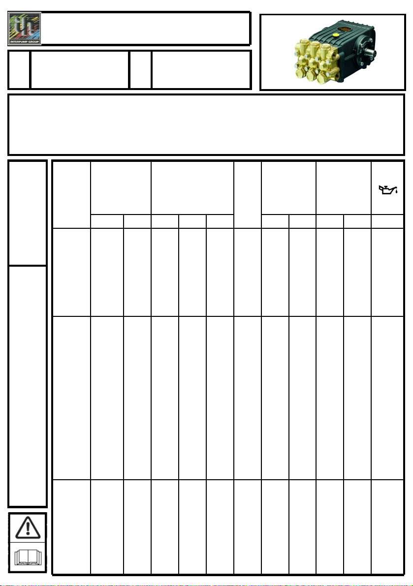
Denominazione: Pompa Tipo: Pompa alternativa a pistoni per acqua ad alta pressione
Marchio di fabbrica: INTERPUMP GROUP Modello: W101 –W131 –W151 –W201 –W92 –W132
W162 –WS133 –WS171 –WS101 –WS131 –WS151 –WS201 –WS92 –WS132 –WS162 –WS82
WS102 –WS152 –WS202 –W913 –W921 –W928 –T9281 –W912 –W916 –W914 –W922
Risulta essere conforme ai requisiti delle sotto elencate direttive e successivi aggiornamenti:
- Direttiva Macchine 2006/42/CE
- Direttiva sulla restrizione dell’uso di determinate sostanze pericolose 2002/95/CE - RoHS
- Direttiva sulla responsabilità del produttore 85/374/CE
UNI EN ISO 12100.1:2005 - UNI EN ISO 12100.2:2005 - UNI EN 809:2000
Firma ________________
La pompa sopra identificata rispetta tutti i requisiti essenziali di sicurezza e di tutela della salute elencati nel
punto 1 dell’allegato I della Direttiva Macchine e la relativa documentazione tecnica è stata compilata in
conformità dell’allegato VII B.
Inoltre il produttore si impegna a rendere disponibile, a seguito di una richiesta adeguatamente motivata,
copia della documentazione tecnica pertinente la pompa nei modi e nei termini da definire.
La pompa non deve essere messa in servizio finché l’impianto al quale la pompa deve essere incorporata è
stato dichiarato conforme alle disposizioni delle relative direttive e/o norme.
Persona autorizzata a costituire il fascicolo tecnico Nome: Maurizio Novelli.
Persona autorizzata a redigere la dichiarazione: L’amministratore delegato Ing. Paolo Marinsek
Reggio Emilia 12/2009
Indirizzo: INTERPUMP GROUP S.p.A. –Via E. Fermi, 25 –42049 S. ILARIO D’ENZA (RE) –Italia
Declaration of incorporation
(According to annex II of European Directive 2006/42/CE).
The manufacturer INTERPUMP GROUP S.p.A. –Via E. Fermi, 25 –42049 S.ILARIO D’ENZA (RE) - Italy
DECLARE that the device identified and described as follows:
Description: Pump Type: High pressure reciprocating pump for water
Trademark: INTERPUMP GROUP Model: W101 –W131 –W151 –W201 –W92 –W132
W162 –WS133 –WS171 –WS101 –WS131 –WS151 –WS201 –WS92 –WS132 –WS162 –WS82
WS102 –WS152 –WS202 –W913 –W921 –W928 –T9281 –W912 –W916 –W914 –W922
Complies with the requirements of the below-listed directives and following updates:
- Directive 2006/42/EC Machinery
- Directive 2002/95/EC Reduction of hazardous substances –RoHS
- Directive 85/374/EC Liability for defective products
UNI EN ISO 12100.1:2005 - UNI EN ISO 12100.2:2005 - UNI EN 809:2000
Signature ________________
The above-mentioned pump complies with all the essential requirements of safety and health protection
listed in annex I, point 1 of the Machinery Directive and the relevant technical documents are compiled in
accordance with annex VII B.
Moreover, in response to a reasoned request, the manufacturer undertake to transmit copy of the technical
documents on the pump within the terms and in the ways to be determined.
The pump must not be put into service until the system into which the pump is to be incorporated has been
declared in conformity with the provisions of the relevant directives and/or norms.
Person authorized to compile the technical documents Name: Maurizio Novelli.
Person empowered to draw up the declaration: Ing. Paolo Marinsek (Managing Director)
Reggio Emilia 12/2009
Address: INTERPUMP GROUP S.p.A. –Via E. Fermi, 25 –42049 S. ILARIO D’ENZA (RE) –Italy
15
This manual suits for next models
27
Table of contents
Other Interpump Group Industrial Equipment manuals