Intewa SEPAMAT E User manual

WATER, WE´RE IN OUR ELEMENT
www.intewa.com
SEPAMAT E
Installation and user manual

SEPAMAT F_Manual_Vers.1.4f_en
1
1.
Introduction and scope of application ............................................................................................... 2
2.
Safety instructions ............................................................................................................................... 2
3.
Scope of delivery.................................................................................................................................. 3
4.
Technical data....................................................................................................................................... 4
4.1
Device overview and dimensions ................................................................................................... 5
4.2
Standards, directives, tests ............................................................................................................ 6
5.
Overview of components..................................................................................................................... 7
5.1
Components of basic controller ...................................................................................................... 7
5.2
Components of diaphragm pump ................................................................................................... 8
5.2.1
.................................................................................................................................
Diaphragm pump
8
5.2.2
......................................................................................................................................................
Fan
8
5.3
Components of the supplemental supply chamber ........................................................................ 9
5.4
Components of the pressure line set.............................................................................................. 9
6.
Installation instructions...................................................................................................................... 10
6.1
Wall mounting ................................................................................................................................ 11
6.2
Connection to the mains water line ............................................................................................... 12
6.3
Installation of the pressure line set................................................................................................ 13
6.4
Connecting the emergency overflow ............................................................................................. 14
7.
Start up and operation modes ........................................................................................................... 15
7.1
Start-up .......................................................................................................................................... 15
7.2
Operation modes ........................................................................................................................... 16
8.
Trouble-shooting ................................................................................................................................. 17
9.
Maintenance......................................................................................................................................... 19
10.
Spare parts........................................................................................................................................... 19
11.
Guarantee............................................................................................................................................. 20
12.
Contact / Device number .................................................................................................................... 20

SEPAMAT F_Manual_Vers.1.4f_en
2
1. Introduction and scope of application
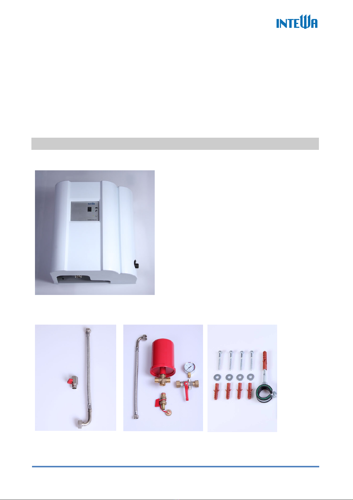
Congratulations on purchasing your SEPAMAT E (Short name, SMT E).
The SMT E is designed as a separation unit, for use with small volume flows.
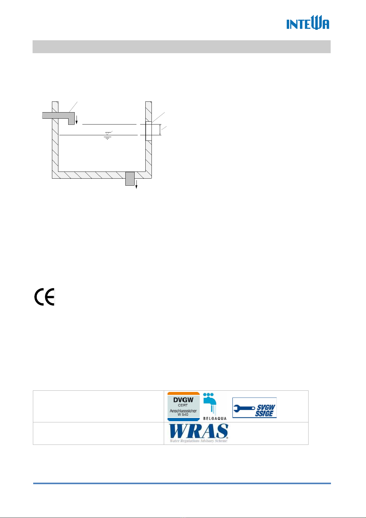
The DVGW certified, fully automatic and ready-to-connect separation unit fulfills the separation of
drinking water from category 5 liquids according to DIN EN 1717.
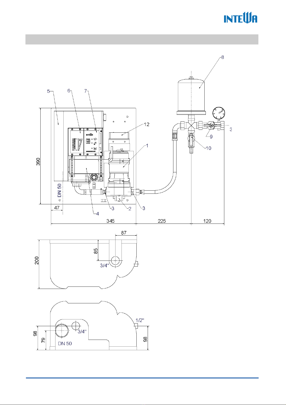
The integrated pump supplies water on-demand from the separation chamber to the users. The
water level in the separation chamber is controlled by a floating valve. The drinking water supply
and emergency overflow are connected to the separation chamber.
The user connection point can be a maximum of 10 m above the SMT E.
2. Safety instructions
The live components have to be installed only by a qualified electrician. In
case of failure of the electronic device, the product has to be repaired by a
qualified electrician before being operated again. There is a risk of electric
shock!
The outlet circuit used for the device has to be secured through a circuit
breaker protected (16 A in several countries). If unavailable, an FI switch with
maximum operating current of 30 mA has to be connected.
These installation and operating guidelines have to be read carefully before
installing the product. The instructions mentioned have to be followed strictly.
Modifications to the product are not permitted, otherwise the warranty
becomes void.
The following points have to be strictly observed during the installation and operation:
•Check the product before installation for any visible defects. If defects are present, then the
product must not be installed. Damaged products can be dangerous.
•Installations at the fresh water pipeline system have to be only performed by a qualified
installation firm.
•A floor drain has to be provided near the installation site, which can collect inadvertent water
discharge (such as with pump defect, pipe breakage etc.) and prevent water damage inside
the building. The brickwork behind the water-carrying system must be protected from water
(such as with water-resistant paint).
•The wall material behind the water-handling system should be protected against water
damage (ie. water-tight coating).
•Make sure that the existing emergency overflows are connected and adequately sized.
•Remove the mains plug if you will be away for more than 24 hours.
•Lock the fresh water line at the inlet of the device if you will be away for more than 24 hours.

SEPAMAT F_Manual_Vers.1.4f_en
3
•All products must be regularly inspected to maintain proper condition. The minimum
inspection interval is mentioned in the maintenance manual.
•Electric devices may be hazardous for children. Therefore children always have to be kept
away from the product. Do not let children play with the product.
•Do not install the water-carrying products in locations where the temperature may drop
below 0 °C.
•Do not install any electric products in flood-prone areas.
•The operator is responsible for adherence of the safety and installation guidelines.
3. Scope of delivery
Separation unit SEPAMAT E
Accessory A
(mains water connection):
Accessory B
(pressure line set):
Accessory C
(wall mounting material)

SEPAMAT F_Manual_Vers.1.4f_en
4
4. Technical data
SEPAMAT E
Dimensions (H x W x D) / Weight: 398 x 353 x 200 mm / 8kg
Switching power supply input: 110-230 V AC / 50-60 Hz
Switching power supply output: 24 V DC ± 5%
Basic controller input: 22-28 V DC
Power consumption: 90 W
Max. operating pressure: 3.5 bar
Max. flow rate: 10 l/min
Pump start-up pressure: ca. 2.4 bar
Noise level: ca. 50-56 dbA
Permitted mains water pressure: 2.5 - 6 bar
Max. height to the user: 10 m
Mains water connection: ½” female
Pressure line connection: ¾” female, union nut
Suction line connection: ¾” male
Emergency overflow connection DN50 (Ø55mm)
Protection class: IP 44
Performance curve for SEPAMAT E

SEPAMAT F_Manual_Vers.1.4f_en
5
4.1 Device overview and dimensions
[1] Diaphragm pump
[2] Pressure switch
[3] Pump connection
(Suction/Pressure)
[4] Switching power supply
[5] Separation chamber
[6] Place holder for fill status indicator
(not for SMT-E)
[7] Basic controller
[8] Expansion tank
[9] Pressure shut-off valve (1/2“ female
)
[10] Vent cock
[12] Fan
Top View
Bottom View

SEPAMAT F_Manual_Vers.1.4f_en
6
4.2 Standards, directives, tests
The SMT E meets the DIN 1989-4 “Components for Control and Supplemental Supply“ standard for
rainwater harvesting systems. The DVGW mark of approval confirms the presence of the
mandatory “air gap“ (as per DIN EN1717) for secure separation of processed water from the mains
water line, which is integrated into the SMT E.
4
1
2
3
Mains water supplemental supply device, Type AB as per DIN EN 1717
The power is supplied via a TÜV GS-certified switching power supply. All components of the SMT E
are run on 24 V DC low voltage technology.
The above mentioned device corresponds with the basic safety and health requirements of the EC
directives for machines. Any modification of the device not coordinated by INTEWA will void the
warranty.
This equipment specifically fulfills the requirements of the following EU directives:
EC directives for machines (89/392/EWG) in accordance with 91/368/EWG
EC Low voltage directives (73/23/EWG)
EG Directives for electromagnetic compatibility (89/336/EWG) in accordance
with 93/31/EWG
The conformity of the equipment with the above mentioned directives is confirmed by the CE
symbol.
Applied harmonized EU standards:
EN 60335-1: 1194/A1/A11/A12/A13/A14, EN 60335-2-41: 1996
Applied standards and technical specifications:
DIN 1988-2, DIN 1989-4, DIN EN1717, DIN EN 13077, BGA KTW
Tests/Monitoring:
Certification separation device according
to EN 1717 and DIN EN 1717
Safety category 5
Mains water separation valve:
WRAS mark certified
1. Mains water inlet, separation chamber
2. Emergency overflow, separation chamber
3. max. possible water level (due to failure)
4. Air gap between inlet and max. possible water level
= secure separation of drinking water from user
water

SEPAMAT F_Manual_Vers.1.4f_en
7
Switching power supply:
TÜV Rheinland, TÜV GS approved
5. Overview of components
The SMT E has a modular design. Each component can be separately changed.
5.1 Components of basic controller
Pos. Description of required connections
1 Fan plug/connector
2 Pump pressure switch (no polarity)
Cabel (blue)
Cabel (blue)
3 Diaphragm pump/Fan
+24 V (red)
GND (black)
4 Switching power supply 24 V DC
- TS connector Ø 5.5, center positive
o

SEPAMAT F_Manual_Vers.1.4f_en
8
5.2 Components of diaphragm pump
5.2.1 Diaphragm pump
5.2.2 Fan
The fan cools the pump by a uniform air flow. If no continuous
operation is provided, the fan can be disconnected electronically.
This saves about 6W power. Nevertheless, if the pump is
operating continuously (without fan) with high back pressure and
the pump is getting too hot, the internal pump temperature sensor
will stop the pump. After cooling down the pump starts
automatically again.
1. Supply cable (red/black)
2. Suction connection (union
nut/grommet)
3. Pressure connection (fix)
4. Non-return valve
5. O-ring
6. Pressure switch with fastener

SEPAMAT F_Manual_Vers.1.4f_en
9
5.3 Components of the supplemental supply chamber
2 cm
3
5
4
1 2
6 cm
The floating valve keeps the water level
constant in the separation chamber. The
maximum water level should be approx.
2-3 cm below the overflow rim when the
floating valves closed (backside of the
container).
The correct distance of the float (5) to the
horizontal lever is factory set at 6 cm.
Note: If an overflow occurs due to
continuous dripping from the valve, the
valve must be decalcified (see section 9).
The floating valve incorporates a
protective sieve.
5.4 Components of the pressure line set
The pressure line set contains an expansion tank, which is necessary to ensure the silent operation
of the system. A pre-pressure of 2.0 bar is preloaded at manufacture. The expansion tank ensures
that the vibration created by the operation of the pump is not transmitted through the piping system.
Procedure for pre-pressure inspection / preparation:
1.) Disconnect the mains power to the SMT E.
2.) Close the pressure shut-off valve.
3.) Open the vent cock to drain till the system pressure is 0 bar.
1. Lid
2. Emergency
overflow rim
3. Floating valve
4. Protective sieve
5. Floating body

SEPAMAT F_Manual_Vers.1.4f_en
10
4.) Check the air pressure through the air valve with an air pump
and gauge (i.e. a bicycle or car tire pump).
If the pressure is too low, use the air pump to increase it
back to the necessary 2.0 bar.
5.) Reconnect the mains power to start the unit again and drain
the water, via the vent cock, until bubble free water gushes
out.
6.) Close the vent cock and open the pressure shut-off valve.
The system is now ready to use.
6. Installation instructions
The foam pieces between the chamber and pump are for
transport safety and must be removed before installation and
start up!

SEPAMAT F_Manual_Vers.1.4f_en
11
6.1 Wall mounting
The SMT E is mounted on the wall using the mounting material provided. The lid, bottom and
lateral distances indicated should be adhered to when mounting to provide clear maintenance
access.
275 mm
340 mm
>200 mm
>400 mm
>300 mm
Ø 8 mm Ø 8 mm
260 mm
>450 mm
The SMT E is fixed horizontally with of Ø8 mm raw plugs
and screws. An additional hole is also drilled 260 mm top
and right of the upper mounting holes for connection of the
expansion tank mounting bracket.
In order to avoid vibrations, the SMT E must be fixed with
all four screws.

SEPAMAT F_Manual_Vers.1.4f_en
12
6.2 Connection to the mains water line
The connection to the mains water line is done with the provided flexible hose with stopcock.
Note:
The flexible hose must not be mounted with tension, since the internal float valve is pressed against
the inner wall from here.
All provided flexible hoses have gland screws with flat seals. The rubber seals must be present.
Additional sealing material must not be used at gland nuts!
Screw the gland screw into the chamber connection and
carefully tighten with a 30 mm fixed wrench.
Screw the gland screw on the other end of the flexible
pipe into the stopcock mounted in the main water line.

SEPAMAT F_Manual_Vers.1.4f_en
13
6.3 Installation of the pressure line set
The pressure line set (see section 3) establishes the connection between the pump and pressure
line system.
The expansion tank is fixed to the wall with the pipe
clamps provided. The vent cock is equipped with a
gasket ring so that it can be screwed directly into the
T-piece without additional gaskets.
The pressure shut-off valve, incorporating the
pressure gauge, is then connected into the line by
screwing the flat sealing gland screw into the
expansion tank T-piece.
The flexible hose connects the pump pressure line to
the other side of the expansion tank T-piece. These
line connections are made with flat sealing gland
screws.
The expansion vessel pressure must be checked (see
section 5.4).

SEPAMAT F_Manual_Vers.1.4f_en
14
6.4 Connecting the emergency overflow
The SMT E has an emergency overflow line (DN 50) which must be connected to the waste
drainage system of the building. The drainage line must be of a size to accommodate a maximum
volume flow rate of 20 l/min.
The position of the backwater level must be taken into consideration while connecting to a drainage
system, in order to prevent backflow of drainage water from the open sewer line (design according
to the DIN EN 1717) entering the SMT E.
The position of the backwater level determines the type of line:
a) Backwater level above the emergency overflow
drainage height of the supplemental supply
container:
Connection of the emergency overflow must be
done by a lifting system.
b) Backwater level below the emergency overflow
drainage height of the supplemental supply
container:
Connection of the emergency overflow to a
ventilated channel line (DN 50) is done via a
siphon.
a.)
b.)

SEPAMAT F_Manual_Vers.1.4f_en
15
7. Start up and operation modes
7.1 Start-up
1.) Check that all lines are connected.
Select mode = Switch position I.
Open the mains water line stopcock so that the separation
chamber is filled with water.
2.) Close the pressure shut-off valve.
3.) Open the air vent (hold a bucket of water under the air vent)
and start the pump by plugging in the mains power.
Let the water run from the air vent into the water bucket until
there is no more sign of bubbles (a clear stream).
4.) Close the air vent.

SEPAMAT F_Manual_Vers.1.4f_en
16
5.) Open the pressure shut-off valve and release the air from the
(house) line (e.g. by flushing the toilet several times).
Close the pressure shut off valve. The pump will automatically
switch off when the maximum system pressure is reached.
7.2 Operation modes
I
0
Unit ON (Normal operation)
When the unit is switched on, the green LED lights up and the pump
will start if the pressure is below 2 bar.
I
0
Fault indication
An emergency shutdown of the unit is indicated by the flashing red
fault LED. The pump is then deactivated.
The pump can only be started again by a RESET (see section 8).

SEPAMAT F_Manual_Vers.1.4f_en
17
8. Trouble-shooting
Description of error Cause Solution
The pump is not starting
and all LEDs are flashing
I
0
The pump has shut down
after running non-stop (2
hours continuous operating)
due to:
a) Anti-dry running
protection
- Air in intake line, as float
switch has not registered
an empty tank and did not
switch to mains water
mode
- Air in intake line because
of a leakage
b) Continuous use by
connected fixture
a)
- Check the functioning and position
of the float switch (see
chapter 6.3.4). After this restart
- Seal connection points and the
intake line and restart
b) Avoid continuous use of more than
two hours
Restart from an Emergency Stop:
-RESET by pulling out the mains plug for at least 5 seconds until all the LEDs have gone
out.
-Plug in the mains plug.
(Should there no longer be water in the line and/or no pressure is built-up, then air has
entered the intake line. The air must be evacuated from the air vent as described in
section 7.2.
Description of error Cause Solution
Pump does not start and
no LED is shining
No power
Check mains supply
Pump does not start but
LED display is o.k.
a) Temperature protection
switch, pump is overloaded
due to continuous use or
pulsating working mode
b) Defective pressure sensor
c) Carbon brushes have worn
out or are defective
a) The pump will automatically
restart if motor is cooled. Find
out the reason for overload and
fix it
b) Change pressure sensor
c) Change pump
Pump does not turn off
a) Power- off pressure is not
obtained (< 3 bar) because
of air in the system
b) Power- off pressure has
exceeded ( > 6,0
bar/90psi) as pressure
switch is defective
a) Evacuate air from the pipeline
system (see section 7.2)
b) Exchange pressure switch.

SEPAMAT F_Manual_Vers.1.4f_en
18
Pump is running
continuously
a) non-sealed leaky fixture
b) withdrawal of water is too
low at the fixture
a) Fix leakage
b) Check fixture
Pump ticks and the LED
light flashes ON/OFF
regularly
The power consumption of the
pump is too high (protection
switching of the power supply
is activated), because:
a) the pressure switch is
defective
(pressure > 6 bar/90psi)
b) Pumping motor is blocked
a) Change pressure switch
(see section 5.2)
b) Change pump
Pump does not attain the
maximum pressure of 3 bar
Air in the system
Evacuate air from the line system
(see section 7.1)
The flow rate is too low or
the pump does not feed
any water
Not enough or no water in the
unit’s separation chamber
Check pre-pressure of mains water,
clean filter sieve in the entry of
mains water valve (see section 5.4)
The pump can be heard
through the walls of the
building
a.) Silencer is not working in
the expansion tank
b) Pump connection or piping
is touching the unit cover
a) Reset the expansion tank‘s pre-
pressure to 2.0 bar (see section
5.5)
b) avoid allowing contact between
the unit cover and the pump and
piping
Separation chamber is
blocked (water spills into
the overflow)
Mains water valve is calcified
Decalcify mains water valve for 24
hrs. (see section 9)

SEPAMAT F_Manual_Vers.1.4f_en
19
9. Maintenance
Description
Maintenance
interval
Pre-pressure of the expansion tank:
For a description for the inspection and
preparation of the pre-pressure see section 5.4
6 months
Mains water valve:
If the mains water valve continuously drips,
then this must be decalcified. Therefore,
remove the entire valve from the tank and
place it in a decalcifying solution (citric acid) so
that the inlet and outlet are fully submerged.
Move the floating arm several times so that the
decalcifying solution penetrates the valve
diaphragm chamber as well (24 hours
exposure time). If the dripping continues after
maintenance, then the valve must be replaced.
6 months
10. Spare parts
Article description
Figure no.
(see section,4.1)
Order name
Diaphragm pump RM Eco 10, inclusive pressure
switch [1]+[2] RM ECO P10
Pressure switch [2] RM ECO PD
Switching power supply 24 VDC, 4 A for RM Eco 10
[4] RM ECO N10
Supplemental supply container [6] RM ECO B
Floating valve [3] see section
5.3 RM ECO NSP
Basic controller [8] RM ECO BPL
Expansion tank RM Eco 10 (1 litre) [10] RM ECO AG1
Table of contents
Other Intewa Water Filtration System manuals
Popular Water Filtration System manuals by other brands

US Water Systems
US Water Systems Fusion Oxi-Gen 089-FSF OG Series Installation, operation and maintenance manual

Paragon
Paragon PW1250UF Installation & operation manual

JRC
JRC NSVS681 manual

Brita
Brita Mypure Instructions for use

Hoshizaki
Hoshizaki HLF 10 manual

Pneumatic Division
Pneumatic Division IS-F35 Installation & service instructions