Intewa SEPAMAT F-SC Series User manual

WATER, WE’ RE IN OUR ELEMENT
www.intewa.de
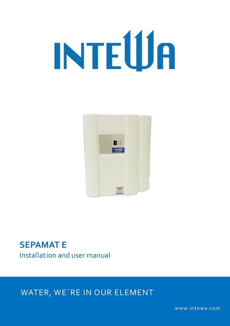
SEPAMAT F-SC
Installation and user manual
WATER, WE´RE IN OUR ELEMENT
www.intewa.com

SEPAMAT F-SC_Manual_Vers.1.0e_en
1
1.
Introduction and scope of application ............................................................................................... 2
2.
Safety instructions ............................................................................................................................... 4
3.
Scope of delivery.................................................................................................................................. 5
4.
Technical Data ...................................................................................................................................... 6
4.1
Device overview and dimensions ................................................................................................... 7
4.2
Standards, directives, tests ............................................................................................................ 9
5.
Overview of components.................................................................................................................... 10
5.1
Components of the pump controller .............................................................................................. 10
5.1.1 Description of display and buttons........................................................................................ 10
5.1.2 Cable connection plan .......................................................................................................... 12
5.1.3 Self-initialization.................................................................................................................... 13
5.1.4 Preferences / Settings / Parameters..................................................................................... 14
5.2
Components of basic controller ..................................................................................................... 17
5.3
Components of the multistage pump............................................................................................. 18
5.4
Components of separation chamber ............................................................................................. 19
6.
Installation instructions...................................................................................................................... 20
6.1
Wall mounting ................................................................................................................................ 20
6.2
Connection to the mains water line ............................................................................................... 21
6.3
Installation of the pressure line set................................................................................................ 22
6.4
Connecting the emergency overflow ............................................................................................. 23
7.
Start-up and use .................................................................................................................................. 24
8.
Safety monitoring and error notifications ........................................................................................ 26
9.
Trouble-shooting ................................................................................................................................. 27
10.
Maintenance......................................................................................................................................... 28
11.
Spare parts........................................................................................................................................... 28
12.
Warranty / Guarantee .......................................................................................................................... 29
13.
Contact / Device number .................................................................................................................... 29
Appendix 1.0 Scope of DUPLEX or TRIPLEX application ................................................................... 30
Appendix 1.1 Technical data for DUPLEX and TRIPLEX application.................................................. 30
Appendix 1.2 Bluetooth function in Duplex and Triplex applications ................................................ 31

SEPAMAT F-SC_Manual_Vers.1.0e_en
2
1. Introduction and scope of application
Congratulations on purchasing your SEPAMAT F-SC (SMT-F-SC).
The SMT-F-SC is designed as a separation unit, for use in single-family homes, apartment
buildings, offices and industry.
The DVGW certified, fully automatic and ready-to-connect separation unit fulfills the separation of
drinking water from category 5 liquids according to DIN EN 1717.
The integrated pump supplies water on-demand from the separation chamber to the consumers.
The water level in the separation chamber is controlled by a floating valve. The drinking water
supply and emergency overflow are connected to the separation chamber.
The highest consumer connection point above the SMT F-SC20 can be a maximum of 20 m and
with SMT F-SC 40 a maximum of 30 m.
The application range can be enlarged and the units connected in parallel series with up to three
SEPAMAT F-SC. The installation control system is communicated through wireless Bluetooth.
Single application
2 3
4
1
1. Expansion vessel
2. Pressure line to the
consumer
3. Mains water connection
DUPLEX application
TRIPLEX application

SEPAMAT F-SC_Manual_Vers.1.0e_en
3
Speed control
In both modes (automatic/maintenance), the speed of the centrifugal pump is controlled by a
frequency converter corresponding to a set pressure level. The pressure is monitored via a built-in
analog pressure sensor. The current is monitored with the basic controller. This ensures 100% that
the pump never dry runs. All operating parameters such as time-delay, idle and load power
consumption and response time for the dry-running are specified by the controller.
Bluetooth connection
Two or three units of SEPAMAT F-SC can communicate with each other wireless via the integrated
Bluetooth and can be conveniently combined into a fully redundant, multiple pumping system. The
consecutive combination, cyclic switching of the pumps, connection with peak load and the
Master/Slave exchange is done automatically in case of the failure of device.

SEPAMAT F-SC_Manual_Vers.1.0e_en
4
2. Safety instructions
The live components have to be installed only by a qualified electrician. In
case of failure of the electronic device, the product has to be repaired by a
qualified electrician before being operated again. There is a risk of electric
shock!
The outlet circuit used for the device has to be secured through a protected
circuit breaker (16 A in most countries). If unavailable, an FI switch with
maximum operating current of 30 mA has to be connected.
These installation and operating guidelines have to be read carefully before
installing the product. The instructions mentioned have to be strictly followed.
Modifications to the product are not permitted, otherwise the warranty
becomes void.
The following points have to be strictly observed during installation and operation:
•Check the product before installation for any visible defects. If defects are present, then the
product must not be installed. Damaged products can be dangerous.
•Installations at the mains water pipeline system can only be performed by a qualified
installation company.
•A floor drain has to be provided near the installation site, which can collect inadvertent water
discharges (i.e. pump defects, pipe breakages, etc.) and prevent water damage inside the
building.
•The mason work behind the water-handling unit must be protected from water damage (i.e.
with water-resistant coating).
•Make sure that the existing emergency overflows are connected and adequately sized.
•Remove the mains electrical plug if you will be away for more than 24 hours.
•Close the mains water line at the inlet of the device if you will be away for more than 24
hours.
•All products must be regularly inspected to maintain proper condition. The minimum
inspection interval is mentioned in the maintenance section.
•Electrical devices may be hazardous for children. Therefore children always have to be kept
away from the product. Do not let children play with the product.
•Do not install the water-handling units in locations where the temperature may drop below
0°C.
•Do not install any electrical products in flood-prone areas.
•The operator is responsible for adherence to the safety and installation guidelines.

SEPAMAT F-SC_Manual_Vers.1.0e_en
5
3. Scope of delivery
Separation unit
SEPAMAT F-SC
Wall mounting material,
installation and user manual
Standard accessory A
(Mains water connection)
Standard accessory B
(Pressure line set)

SEPAMAT F-SC_Manual_Vers.1.0e_en
6
4. Technical Data
SEPAMAT F
-
SC 20
SEPAMAT F
-
SC 40
Dimensions (H x W x D): 595 x 550 x 265 mm 595 x 550 x 265 mm
Weight: 33 kg 34 kg
Nominal voltage / frequency : 230 V / 50-60 Hz 230 V / 50-60 Hz
Rated voltage: 207 ... 244 V 207 ... 244 V
Rated power: max. 0.8 kW max. 1.25 kW
Supply voltage / frequency: 3 x 230 V / 0-55Hz 3 x 230 V / 0-55Hz
Rated current: max. 2.6 A max. 3.5 A
Discharge pressure:
2.0 – 4.5 bar (adjustable) 2.0 – 5.5 bar (adjustable)
Max. flow rate:
80 l/min 110 l/min
Noise level (speed dependent): 35 - 60 dBA ca. 35 - 65 dBA
Protection class: IP 54 IP 54
Mains water pressure: 2.5 - 6 bar 2.5 - 6 bar
Max. highest connected fixture: 20 m 30 m
Performance curves for SEPAMAT F-SC20/40 Single
SEPAMAT F
-
SC 40
SEPAMAT F
-
SC
2
0

SEPAMAT F-SC_Manual_Vers.1.0e_en
7
4.1 Device overview and dimensions
Left side view
Right side view Front view

SEPAMAT F-SC_Manual_Vers.1.0e_en
8
1. Multistage centrifugal pump SEPAMAT F-SC 20 /
40
2. Pump terminal box with basic controller
3. Vent cock
4. Pressure line shut-off valve (1“ female)
5. Pump controller
6. Pressure sensor 4-20 mA, ¼“ male
7. Separation chamber
8. Stopcock for mains water (3/4“ female)
9. Mains water floating valve
10. 3/2-way valve (only for RAINMASTER F version)
11. Suction side connection (only for RAINMASTER
F version)
12. Emergency overflow (DN50)

SEPAMAT F-SC_Manual_Vers.1.0e_en
9
4.2 Standards, directives, tests
The SMT F-SC meets the DIN 1989-4 “Components for Control and Supplemental Supply“
standard. The DVGW mark of approval confirms the presence of the mandatory “air gap“ (as per
DIN EN1717) for secure separation of processed water from the mains water line, which is
integrated into the SMT F-SC.
4
1
2
3
Mains water separation device, Type AB as per DIN EN 1717
The above mentioned device corresponds with the basic safety and health requirements of the
EC directives for machines. Any modification of the device not coordinated by INTEWA will void the
warranty. This equipment specifically fulfils the requirements of the following EU directives:
EG-Directives for machines (89/392/EWG) in accordance with 91/368/EWG
EG-Low-voltage directives (73/23/EWG)
EG-Directives for electromagnetic compatibility (89/336/EWG) in accordance
with 93/31/EWG
The conformity of the equipment with the above mentioned directives is confirmed by the CE
symbol.
Applied harmonized EU standards:
EN 60335-1: 1194/A1/A11/A12/A13/A14, EN 60335-2-41: 1996
Applied standards and technical specifications:
DIN 1988-2, DIN 1989-4, DIN EN1717, DIN EN 13077, BGA KTW
Tests/Monitoring:
Mains water supplemental supply device:
Mains water supplemental valve:
WRAS mark certified
1. Mains water inlet to separation chamber
2. Emergency overflow opening
3. Max. possible water level (in case of
malfunction)
4. Air gap between inlet and max. possible water
level = secure separation of mains water and
usage water

SEPAMAT F-SC_Manual_Vers.1.0e_en
10
Button Description
+
- increases the discharge pressure by
0.5 bar per keystroke (possible at any
time during operation)
- raises the setting in the setting mode in
one step
- reduces the discharge pressure by 0.5
bar per keystroke (possible at any
time during operation)
- lowers the setting in the setting mode
in one step
START
START
- starts the pump with the first self-
initialization or after a RESET
STOP
STOP
- instantaneous stop of the pump
5. Overview of components
The SMT-F-SC has a modular design. Each component can be separately exchanged.
5.1 Components of the pump controller
The pump controller (see section 4.1) monitors
the pressure in pressure line system and
maintains it at a constant level by speed
controller. The controller reduces power
consumption especially with small flow rates and
increases the service life of the pump.
1. Motor pump (OUT), 3-phase
2. Pressure sensor (4-20 mA output), ¼” male
3. Power supply 230 V AC/50Hz
5.1.1 Description of display and buttons
1 2 3

SEPAMAT F-SC_Manual_Vers.1.0e_en
11
LED-Indicator Description
POWER
POWER
Green, steady: Inverter voltage supply is ON
PUMP ON
PUMP ON
Green, steady: Pump ON
Green, flashing: Enable OFF condition
ALARM
ALARM
Red, steady: Pump stopped due to a malfunction
Restart necessary (STOP then START)
Red, flashing: Pump stopped due to a malfunction (auto restart)
Minimum
Flow
Minimum Flow
Yellow, steady: Pump stopped due to flow rate below defined
minimum (see setting F1)
Yellow, flashing: Minimum flow rate reached, defined time-delay is
active (see setting F14)
Dry
Working
Dry Working
Red, flashing: Pump stopped due to dry running, currently in one of
four automatic 15 min restart periods
Red, steady: Final stop after 5
th
automatic restart malfunction
Segmented LED indicator
- indicator of discharge pressure in 0.5 bar steps
- indicates the adjustment of pressure for 3 seconds after pressing
+
or
- settings indicator in setting mode
- indicator of alarms based on malfunction code

SEPAMAT F-SC_Manual_Vers.1.0e_en
12
5.1.2 Cable connection plan
In the event of a damaged cable or faulty pressure sensor, it is necessary to open the housing of
the pump control. To do this, the mains plug must be disconnected and you have to wait for at least
2 minutes until all LEDs turn off (internal capacitors are discharged). You may open the case only
after this. To do this, you have to demount the complete pump control from the angle holders. Then
the rear screws of the heatsink can be opened.
Mains input connector (230 V / 50
Hz)
Pump connector (3 ~230V÷400 V)
Pressure sensor (4-20 mA output)
S (white cable)
+15 V (brown cable)

SEPAMAT F-SC_Manual_Vers.1.0e_en
13
5.1.3 Self-initialization
Each SMT-F-SC pump is factory set for the initial pump control!
The below described self-initialization must be performed only when a program RESET was
conducted or if a new pump or a new pump control was installed.
In this automatic initialization, the characteristic current values are analysed at different operating
parameters, which form the basis of the speed controller.
1.)Make sure the pump is automatically primed with water (see section 7.1) when it first begins
operation.
2.)Open the air vent and let water flow out until there is no more air in the system. Then close the
pressure shutoff valve (pressure increases).
3.) In case the pressure of the system is > 3 bar, the stopcock must be opened again to reduce the
pressure to < 3 bar.
4.)Press
START
to start the self-initialization. After about two minutes (total pressure range of the
pump is analysed) the initialization is finished. The segmented LED indicator lights up one time,
from 0 all the way to 10 bar and the pump stops (LED Minimum Flow lights up).
5.)The self-initialization is now finished and the start-up procedure can follow (see section 7.2).
Changing the predefined discharge pressure of 3 bar is possible, if necessary, in 0.5 bar steps
by pressing the
+
or button (the pressure setting has been saved once the
segmented LED no longer blinks).
Command Button combination
RESET
(to restore factory
settings)
&
STOP
press simultaneously for 5 seconds (total
segmented LED indicator blinks once).
Pull the mains plug and wait until all the LEDs are off.
SELF-INITIALIZATION
Plugin the mains plug.
Press
START
to start the self-initialization.
Checking the pump start and stop
At the end of the self-initialization, test the start and stop of the pump system by turning on one or
more fixtures. When the pump stops, the yellow LED Minimum Flow will flash. When the fixtures
are opened, the pump must independently start again.
Checking the dry-running protection
In cases of water shortage, the pump must stop after 40 secs and the red LED Dry Working turn
on. This check is best performed by shutting the mains water supply valve and opening a fixture.

SEPAMAT F-SC_Manual_Vers.1.0e_en
14
5.1.4 Preferences / Settings / Parameters
In the default setting, the parameters are predefined for the SMT-F-SC pump. However, the option
exists to define precise parameters in the setting mode.
Attention!
This should only be performed by an experienced technician.
Command Button combination
Activation of setting
mode
STOP
&
+
press simultaneously for about 3 seconds until the
total segmented LED indicator blinks once and the setting F1 is
displayed.
Display next setting
value Keep the
STOP
button pressed. By pressing
+
, the next setting
value is selected.
By releasing the buttons, the current setting value is shown.
Adjust setting value
By pressing
+
or the value is increased or
decreased (the segmented LED indicator displays up to 20 Steps).
Confirm the setting
value By pressing
START
you confirm the settings and exit the setting mode.

SEPAMAT F-SC_Manual_Vers.1.0e_en
15
Code
LED
-
Display
Function
Description
Range
Default
setting
F1
Minimum
flow rate stop
Setting of the minimum flow
rate level
10...+10
Each step: 1
0
F2
Maximum
motor current
Setting of the maximum
motor current
SMT-F-SC20: 3.0 A
SMT-F-SC40: 3.5 A
1...7 A
Each step: 0.5
A
7 A
F3
Minimum
motor speed
Setting of the minimum
motor speed (Reference of
the nominal speed is
2850 min
-1
)
30..70%
Each step: 2%
50%
F4
Maximum
motor speed
Setting of the maximum
motor speed (Reference of
the nominal velocity is 2850
min
-1
)
90..110%
Each step: 1%
105%
F5
Rotation
direction
0/1 0/1 0
F6
Starting
RPM ramp-up
RPM during acceleration 1000-10000
RPM/s
Each step: 500
3000
RPM/s
F7
Maximum
operating
pressure
Maximum system pressure
that should not be
exceeded
2 ...10 bar
Each step:
0.5 bar
10 bar
F8 Pressure
hysteresis
Setting of the maximum
pressure hysteresis
(difference between switch
point and reset point)
0.15 ..1 bar
Each step: 0.05
bar
0.3 bar
F9 Pressure
ramp-up
Setting for the rate of
pressure increase or
decrease
0.1 … 2 bar/s
Each step:
0.1 bar/s
1 bar/s
F10 Pressure sensor
minimum output
signal
Setting for the minimum
output signal from the
pressure sensor
1..5 mA
Each step:
0.2 mA
4 mA
F11 Pressure sensor
maximum output
signal
Setting for the maximum
output signal from the
pressure sensor
10.. 20 mA
Each step:
0.5 mA
20 mA

SEPAMAT F-SC_Manual_Vers.1.0e_en
16
Code
LED
-
Display
Function
Description
Range
Default
setting
F12 Pressure sensor
operating range
Setting for the operating
range of the pressure
sensor
10..20 bar
Each step:
0.5 bar
16 bar
F13 Proportional
P.I.D.
Factor
Setting for proportional
factor in P.I.D.
(Proportional-Integral-
Derivative) for pressure
control
0..6000
Each step: 300
3000
F14 Integral P.I.D.
Factor
Setting for integral factor in
P.I.D. (Proportional-Integral-
Derivative) for pressure
control
0..4000
Each step: 200
1000
F15 Minimum flow
time delay
Setting for time delay on the
minimum flow condition
before stopping pump.
2..20 sec
Each step:
1 sec
12 sec
F16 Dry running
time delay
Setting for time delay on the
dry running condition before
stopping pump.
10..100 sec
Each step:
5 sec
40 sec
F17 Master-Slave
group
communication
Operating mode with 1, 2 or
3 pumps with Bluetooth
connection, factory setting
for 2 pump system that also
functions for single pump
mode
1: one pump
2: two pumps
MASTER/SLAV
E
3: three pumps
MASTER/SLAV
E
2
F18 Setting check Refers to the graph of the
power consumption
0: theoretical
curve
1: self-
initialization
2: tested curve
1
F19 Measurements Measures of different
parameters
0: Pressure
(0..10)
1: Frequency
(15..55)
2: Current
(0..10)
3: Voltage (200-
.240)
4: T [°C]
(70..90)
5: Last alarm
6: Motor
ΔT[°C](0..100)
0
F20 Frequency
transmission
Frequency of transmission/
reception of the radio
communication between 2
or 3 controllers
780 .. 820 MHz
Each step: 1
MHz
800 MHz

SEPAMAT F-SC_Manual_Vers.1.0e_en
17
5.2 Components of basic controller
The unit’s basic controller is located in the terminal box of the pump. Here are all the electronic
components of the SMT-F-SC are connected. On the side of the terminal box is the mode
selections switch I / II for Automatic and Maintenance mode (see section 7.3 for functional
description).
1. Mains connection ~230V AC/50 Hz
2. Mains pump control
3. Pump control OUT, 3-phase
Pos. Board code Connection description Pos
. Board code Connection description
1
2
3
4
5
6
7
8
9
10
11
NE PE
ST PE
NE bl
NE ST bl
NE ST br
ST1 br
PUIN1
ST2 grey
PUIN2
ST3 black
PUIN3
Ground mains connection
Ground pump control
Mains connection 230 V, blue
Mains pump control, blue
Mains pump control, brown
OUT-Pump control, brown
IN-Pump, brown
OUT-Pump control, grey
IN-Pump, grey
OUT-Pump control, black
IN-Pump, black
12
13
14
15
16
17
18
19
20
21
22
NE ST PE
PU PE
SS PE
NE br
SS br
SS bl
S2 bl
S1 br
KH black
KH gr
KH red
Ground pump
Ground pump control
free
Mains connection 230 V,
brown
free
free
free
free
free
free
free
Table: Overview of the cable connections
1
2
3

SEPAMAT F-SC_Manual_Vers.1.0e_en
18
5.3 Components of the multistage pump
Exploded view of the SMT F-SC 20 / 40 centrifugal pump.
KIT
REF.
Nr. KIT
DESCRIPTIO
N
REF.Nr
.COMPONENT DESCRIPTION
25 O-RING ( PUMP BODY ~ )
1
24 SEAL ( COMPLETE
1
21 IMPELLER 1 pcs.
1
12 DIFFUSER ( WELDED ~ ) 1 pcs.
1
380 CAPACITOR 47 CAPACITOR ZBR
1
-- ZBR
1
--
16 16 O-RING ( NOZZLE ~ ) 1 pc
1
84 84 PLUG (FRONT ~ ) 1 pc
1
88 88 SHUTTER 1 pc
1
490 490 RUBBER SPACER 1 pc
1
89 89 SPRING ( SHUTTER ~ ) 1 pc
1
370 370 SELF-PRIMING SUCTION
1
RM F 20
SMT F 20
RM F-SC 20
SMT F-SC 20
RM F 40
SMT F 40
RM F-SC 40
SMT F-CS 40
371 MECHANICAL
SEAL KIT ZBR25620
372 HYDRAULIC
KIT ZBR24170 ZBR24180
473 SELF-
PRIMING
SUCTION
FLANGE KIT ZBR28140
List of spare parts for SMT F-SC 20/40 centrifugal pump

SEPAMAT F-SC_Manual_Vers.1.0e_en
19
5.4 Components of separation chamber
The floating valve keeps the water level
constant in the separation tank. The
maximum water level should be approx. 2-
3 cm below the overflow rim when the
floating valves closed (backside of the
container).
The correct distance of the float (5) to the
horizontal lever is factory set at 8.5 cm.
Note: If an overflow occurs due to continuous
dripping from the valve, the valve must be
decalcified (see Maintenance).
The floating valve incorporates a protective
sieve.
1. Separation chamber
2. Floating valve
3. Protective sieve
4. Emergency overflow rim
5. Floating body
6. Maximum water level
7. Emergency overflow
This manual suits for next models
2
Table of contents
Other Intewa Water Filtration System manuals
Popular Water Filtration System manuals by other brands

BRIGHT BLUE
BRIGHT BLUE COLIBRI manual

bora
bora Universal recirculation unit 1 Operating and installation instructions

Levoit
Levoit True HEPA LV-PUR131-RF instructions

Oase
Oase Filtral UVC 700 operating instructions

Toro
Toro 115-4029 installation instructions

OWA
OWA Mycare MP50 Installation and operating instructions