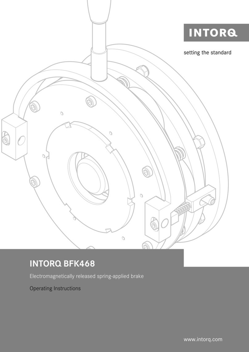
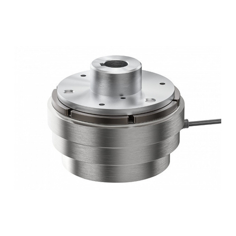
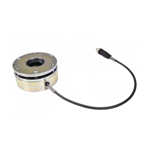
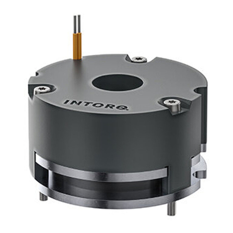
INTORQ BFK468 User manual

Operating Instructions INTORQ BFK468
Spring-applied brake with electromagnetic release
j
setting the standard
www.intorq.de

j| BA 14.0190 - EN | 02/2007
2
Product key INTORQ BFK
-
Legend for INTORQ BFK468 product key
Product group Brakes
Product family Spring-applied brake
Type 468
Size 18, 20, 25, 31
Design E - adjustable (brake torque can be reduced via adjuster nut)
N - not adjustable
Not coded: Supply voltage, hub bore, options
Nameplate
Field Contents Example
1Manufacturer CE mark
BFK468-25N
205V DC 528/132W 65H7
Nr.: 479714 800NM 01.03.05
D-Aerzen
j
2Brake type
3Rated voltage Rated power Hub diameter
4Type no. Rated torque Date of manufacture
Packaging sticker
Field Contents Example
1Manufacturer Barcode no.
D-Aerzen
Typ: BFK468-25N Nr. 479714
205V DC 528/132W 010305
Rostschutzverpackung-Reibfläche fettfrei halten
FEDERKRAFTBREMSE 800NM 1 Stück
j
2Name Type no.
3Type see Product key Rated torque Qty. per box
4Rated voltage / rated power Date of packaging
5Addition / CE mark
0Fig. 0Tab. 0
© 2007 INTORQ GmbH & Co KG, Wülmser Weg 5, D-31855 Aerzen
No part of this documentation may be reproduced or made accessible to third parties without written consent by
INTORQ GmbH & Co KG.
All information given in this documentation has been selected carefully and complies with the hardware and software described.
Nevertheless, discrepancies cannot be ruled out. We do not take any responsibility or liability for any damage that may occur. Necessary
corrections will be included in subsequent editions.

Contentsi
i
j| BA 14.0190 - EN | 02/2007
3
1 Preface and general information 4.......................................
1.1 How to use these Operating Instructions 4...............................
1.2 Terminology used 4.................................................
1.3 Scope of supply 4..................................................
1.4 Labelling 5........................................................
1.5 Legal regulations 5.................................................
2 Safety instructions 6...................................................
2.1 General safety information 6..........................................
2.2 Definition of notes used 8............................................
3Technicaldata 9.......................................................
3.1 Product description 9...............................................
3.2 Brake torques 11...................................................
3.3 Rated data 12......................................................
3.4 Operating times 14..................................................
3.5 Operating frequency / friction work 15..................................
3.6 Emission 16.......................................................
4 Mechanical installation 17................................................
4.1 Necessary tools 17..................................................
4.2 Mounting 17.......................................................
4.3 Installation 18......................................................
5 Electrical installation 25.................................................
5.1 Bridge/half-wave rectifiers 25.........................................
5.2 Electrical connection 27..............................................
6 Commissioning and operation 31..........................................
6.1 Functional test 31...................................................
6.2 Reducing the brake torque 35.........................................
6.3 During operation 35.................................................
7 Maintenance/repair 36..................................................
7.1 Inspection intervals 36...............................................
7.2 Inspections 36......................................................
7.3 Maintenance operations 37............................................
7.4 Spare-parts list 39..................................................
7.5 Spare-parts order 40.................................................
8 Troubleshooting and fault elimination 41...................................
9Disposal 43............................................................

Preface and general information1
j| BA 14.0190 - EN | 02/2007
4
1 Preface and general information
1.1 How to use these Operating Instructions
| These Operating Instructions will help you to work safely on and with the
spring-applied brake with electromagnetic release. They contain safety instructions
that must be followed.
| All persons working on or with the electromagnetically released spring-applied brakes
must have the Operating Instructions available and observe the information and notes
relevant for them.
| The Operating Instructions must always be in a complete and perfectly readable state.
1.2 Terminology used
Term In the following text used for
Spring-applied brake Spring-applied brake with electromagnetic release
Drive system Drive systems with spring-applied brakes and other drive components
1.3 Scope of supply
| The drive systems are combined individually according to a modular design. The scope
of delivery is indicated in the accompanying papers.
| After receipt of the delivery, check immediately whether it corresponds to the
accompanying papers. INTORQ does not grant any warranty for deficiencies claimed
subsequently. Claim
– visible transport damage immediately to the forwarder.
– visible deficiencies / incompleteness immediately to INTORQ GmbH & Co.KG.

Preface and general information1
i
j| BA 14.0190 - EN | 02/2007
5
1.4 Labelling
Drive systems and drive components are clearly labelled and defined by the indications on the
nameplates.
Manufacturer: INTORQ GmbH & Co KG, Wülmser Weg 5, D-31855 Aerzen
| The INTORQ spring-applied brakes are also available as individual components. The
user can built up the system as required. The following indications: packaging sticker,
nameplate, and type code are valid for the spring-applied brake.
| If individual parts are supplied, there is no identification.
1.5 Legal regulations
Liability
| The information, data and notes in these Operating Instructions met the state of the
art at the time of printing. Claims referring to drive systems which have already been
supplied cannot be derived from the information, illustrations and descriptions.
| We do not accept any liability for damage and operating interference caused by:
– inappropriate use
– unauthorised modifications to the drive system
– improper working on and with the drive system
– operating faults
– disregarding these Operating Instructions
Warranty
| Terms of warranty: see terms of sale and delivery of INTORQ GmbH & Co. KG.
| Warranty claims must be made to INTORQ immediately after detecting defects or
faults.
| The warranty is void in all cases where liability claims cannot be made.

Safety instructions2
j| BA 14.0190 - EN | 02/2007
6
2 Safet y instructions
2.1 General safety information
| These safety notes do not claim to be complete. If any questions or problems occur,
please contact INTORQ GmbH & Co. KG.
| The spring-applied brake met the state of the art at the time of delivery and is
generally safe to operate.
| The spring-applied brake is hazardous to persons, the spring-applied brake itself and
other properties of the operator if
– non-qualified personnel work on and with the spring-applied brake.
– the spring-applied brake is used improperly.
| The spring-applied brakes must be planned in such a way that if they are correctly
installed and used for their designed purpose in fault-free operation, they fulfil their
function and do not put any persons at risk. This also applies to the interaction thereof
with the overall system.
| Take appropriate measures to ensure that the failure of the spring-applied brake will
not lead to damage to material.
| Do not operate the spring-applied brake unless it is in perfect condition.
| Retrofittings, modifications and changes of the drive system are generally forbidden. In
any case, INTORQ GmbH & Co. KG must be contacted beforehand.
| The friction lining and the friction surfaces must be carefully protected from oil or
grease since even small amounts of lubricants reduce the brake torque considerably.
| The braking torque will usually not be influenced if the brake is used under the
environmental conditions that apply to IP54. Because of the numerous possibilities of
using the brake, it is however necessary to check the functionality of all mechanical
components under the corresponding operating conditions.

Safety instructions2
i
j| BA 14.0190 - EN | 02/2007
7
2.1.1 Personnel responsible for safety
Operator
| An operator is any natural or legal person who uses the spring-applied brake or on
whose behalf the spring-applied brake is used.
| The operator or his safety personnel must ensure
– that all relevant regulations, notes and laws will be complied with,
– that only qualified personnel will work on and with the drive system,
– that the Operating Instructions will be available to the personnel working on and with
the brake at all times,
– that unqualified personnel will not be allowed to work on and with the spring-applied
brake.
Skilled personnel
Skilled personnel are persons who -because of their education, experience, instructions, and
knowledge about corresponding standards and regulations, rules for the prevention of
accidents, and operating conditions - are authorised by the person responsible for the safety
of the plant to perform the required actions and who are able to recognise potential hazards.
(See IEC 364, definition of skilled personnel)
2.1.2 Application as directed
| Drive systems
– are intended for use in machinery and systems.
– must only be used for the purposes ordered and confirmed.
– must only be operated under the ambient conditions prescribed in these Operating
Instructions.
– must not be operated beyond their corresponding power limits.
Any other use shall be deemed inappropriate!
Possible applications of the INTORQ spring-applied brake
| No explosive or aggressive atmosphere.
| Humidity, no restrictions.
| Ambient temperature -20°C to +40°C.
| With high humidity and low temperatures
– Take measures to protect armature plate and rotor from freezing.
| Protect electrical connections against contact.

Safety instructions2
j| BA 14.0190 - EN | 02/2007
8
2.2 Definition of notes used
The following pictographs and signal words are used in this documentation to indicate dangers
and important information:
Safety instructions
Structure of safety instructions:
Danger!
Characterises the type and severity of danger
Note
Describes the danger
Possible consequences:
| List of possible consequences if the safety instructions are disregarded.
Protective measure:
| List of protective measures to avoid the danger.
Pictograph and signal word Meaning
Danger!
Danger of personal injury through dangerous electrical voltage
Reference to an imminent danger that may result in death or serious
personal injury if the corresponding measures are not taken.
Danger!
Danger of personal injury through a general source of danger
Reference to an imminent danger that may result in death or serious
personal injury if the corresponding measures are not taken.
Stop!
Danger of property damage
Reference to a possible danger that may result in property damage if the
corresponding measures are not taken.
Application notes
Pictograph and signal word Meaning
Note!
Important note to ensure troublefree operation
Tip!
Useful tip for simple handling
Reference to another documentation

Technical data3
i
j| BA 14.0190 - EN | 02/2007
9
3Technicaldata
3.1 Product description
12
3
4
5
6
8
9
7
KL 46820-003.iso
Fig. 1 Design of the spring-applied brake INTORQ BFK468: basic module E (complete stator) + rotor +
hub + flange
1Armatureplate 4Hub 7Stator
2 Compression springs 5 Shaft 8 Adjuster nut
3 Rotor 6 Flange 9 Threaded sleeves
12
3
4
5
6
9
7
KL 46820-001.iso
Fig. 2 Design of the spring-applied brake INTORQ BFK468: basic module N (complete stator) + rotor +
hub + flange
1Armatureplate 4Hub 7Stator
2 Compression springs 5 Shaft 9 Threaded sleeves
3 Rotor 6 Flange

Technical data3
j| BA 14.0190 - EN | 02/2007
10
3.1.1 General information
The spring-applied brake INTORQ BFK468- is a single-disk brake with two friction
surfaces. The brake torque is generated by several compression springs (2) by friction. The
brake is released electromagnetically with holding current reduction via an INTORQ
bridge/half-wave rectifier.
The spring-appliedbrake is designed for the conversion of mechanical work and kinetic energy
into heat. For operating speed, see chapter 3.3 Rated data. Due to the static brake torque,
the brake can hold loads without speed difference. Emergency braking is possible at high
speed, see chapter 3.3 Rated data. The more friction work, the higher the wear.
The stator (7) is designed in thermal class F. The limit temperature of the coils is 155°C.
3.1.2 Braking
During braking, the rotor (3), which is axially movable on the hub (4), is pressed against
the friction surface - via the armature plate (1) - by means of the inner and outer springs
(2). The asbestos-free friction linings ensure a high brake torque with low wear. The brake
torque is transmitted between hub (4) and rotor (3) via the splines.
3.1.3 Brake release
In braked state, there is an air gap ”s
Lü”
between stator (7) and armature plate (1). To release
the brake, the stator coil (7) is excited with the DC voltage provided. The magnetic force
generated attracts the armature plate (1) towards the stator (7) against the spring force. The
rotor (3) is then released and can rotate freely.
3.1.4 Reducing the brake torque
For basic module E (adjustable), the spring force and thus the brake torque can be reduced
by unscrewing the adjuster nut (8) (35).
3.1.5 Manual release (optional for sizes 18 to 25)
The manual release is optionally available for short-term releases when no voltage is applied.
The manual release can be retrofitted.
3.1.6 Microswitch (optional)
The manufacturer offers the microswitch for air-gap or wear monitoring. The user must provide
the corresponding electrical connection (27 following).
When air-gap monitoring, the motor does not start before the brake has been released. With
this set-up, all possible faults are monitored. For example, in the event of defective rectifiers,
interrupted connection cables, defective coils, or excessive air gaps the motor will not start.
When checking the wear, no current will be applied to the brake and the motor if the air gap
is too large.

Technical data3
i
j| BA 14.0190 - EN | 02/2007
11
3.1.7 Encapsulated design (optional)
This design not only avoids the penetration of spray water and dust, but also the spreading
ofabrasionparticlesoutsidethebrake.Thisisachievedby:
| a cover seal over the armature plate and rotor,
|acoverintheadjusternut,
| a shaft seal in the adjuster nut for continuous shafts (option).
3.2 Brake torques
Stop!
Please observe that engagement times and disengagement times change
depending on the brake torque.
Size 18 20 25 31
Rated
torque
Torque
reduction E
per detent
position
Rated
torque
Torque
reduction E
per detent
position
Rated
torque
Torque
reduction E
per detent
position
Rated
torque
[NM] [NM] [NM] [NM] [NM] [NM] [NM]
230 N
Rated torques [Nm],
referring to the
relative speed Δn=
100 min-1
Depending on the
rated torque (spring
assembly), the angle
of rotation for the
brake torque
reduction can be
60°, 120° or 180°
for basic module E.
100 N/E 6.4 170 N/E 19.8 260 N/E 16.5
115 N/E 6.4 200 N/E 19.8 300 N/E 8.2 720 N
130 N/E 6.4 230 N/E 9.9 350 N/E 8.2 960 N
150 N/E 3.2 260 N/E 9.9 400 N/E 8.2 1200 N
165 N/E 3.2 300 N/E 19.8 445 N/E 16.5 1440 N
185 N/E 6.4 345 N/E 19.8 490 N/E 8.2 1680 N
200 N/E 6.4 400 N/E 19.8 520 N/E 16.5 1920 N
235 N/E 6.4 440 N/E 19.8 600 N/E 16.5 2160 N
265 N/E 6.4 480 N/E 19.8 700 N/E 16.5 2400 N
300 N/E 6.4 520 N/E 19.8 800 N/E 16.5
Tab. 1 N.....Brake torque for module N (without adjuster nut)
E......Brake torque for module E (with adjuster nut)
Holding brake with emergency stop operation (sLümax. approx. 2.0 x sLürated)
Service brake (sLümax. approx. 4.0 x sLürated)
Standard brake torque
3.2.1 Basic module E, brake torque reduction
For basic module E, the brake torque can be reduced by means of the adjuster nut in the
stator. The adjuster nut may only be screwed out up to the maximum projection ”h
Emax.
”
( 12).

Technical data3
j| BA 14.0190 - EN | 02/2007
12
3.2.2 Brake torques depending on the speed and permissible limit speeds
Type Rated brake
torque at Δn = 100
min-1
BraketorqueatΔn0[min-1][%] max. speed
Δn0max. with
horizontal
mounting position
[%] 1500 3000 maximum [min-1]
INTORQ BFK468-18
100
77 70
66
4400
INTORQ BFK468-20 75 68 3700
INTORQ BFK468-25 73 66 3000
INTORQ BFK468-31 69 ----- 2300
Tab. 2 Brake torques depending on the speed and permissible limit speeds
3.3 Rated data
Type sLürated
+0.1 mm
-0.05 mm
sLümax.
service
brake
sLümax.
holding
brake
max.
adjustment,
permissible
wear
Rotor thickness Excess
of the
adjuster nut
hEmax.
[mm] [mm] [mm] [mm] min. 1) [mm] max. [mm] [mm]
INTORQ BFK468-18
0.4
1.0 0.6 3.0 10.0 13.0 15
INTORQ BFK468-20
1.25
4.0 12.0 16.0 17
INTORQ BFK468-25
0.5
0.75 4.5 15.5 20.0 19.5
INTORQ BFK468-31 1.5 1.0 3.0 15.0 18.0 ----
Type Pitch circle Screws for
flange
installation
DIN912 10.9
Minimum
depth of the
clearing
holes
(installation
flange)
Tightening torque Weight
of complete
stator
[mm] Thread 2) [mm] Screws [Nm] Complete
lever [Nm]
[kg]
INTORQ BFK468-18 196 6xM8 4xM83) 0.8 34 23 13.4
INTORQ BFK468-20 230
6xM10
4xM103) 2.1
67 40
20.0
INTORQ BFK468-25 278 6xM10
5
31.0
INTORQ BFK468-31 360 8xM16 8xM16 195 ----- 55.1
Tab. 3 Rated data - spring-applied brake INTORQ BFK468
1) The friction lining is designed such that the brake can be adjusted at least 5 times.
2) The screw length depends on the material and thethicknessofthecustomer’smountingplace.
3) The thread in the threading surface is offset by 30° in reference to the center axle of the manual release lever.

Technical data3
i
j| BA 14.0190 - EN | 02/2007
13
Type Electrical power P20 1) Release voltage/holding voltage
U
Coil resistance R20 ±8%
[W] [V] [Ω]
INTORQ BFK468-18 85 / 340
205 / 103 123.5
360 / 180 381.5
INTORQ BFK468-20 100 / 408
205 / 103 106.1
360 / 180 317.6
INTORQ BFK468-25 132 / 528
205 / 103 79.6
360 / 180 245.5
INTORQ BFK468-31 230 / 920 360 / 180 140.9
Tab. 4 Coil voltage/coil resistance of INTORQ BFK468
1)
Coil power at 20_C

Technical data3
j| BA 14.0190 - EN | 02/2007
14
3.4 Operating times
K14.0583
Fig. 3 Operating times of the INTORQ spring-applied brakes
t1Engagement time t11 Reaction delay during engagement
t2Disengagement time (up to M = 0.1 Mr)t
12 Rise time of the brake torque
Type Rated brake
torque at Δn=
100 min-1
Max. permissible
friction work per
operation only
Transition
operating
frequency
Operating times [ms] for sLürated
Mr1) QEshü Engaging DC-switching Disengag
ing
[NM] [J] [h-1] t11 t12 t1t2
INTORQ BFK468-18 150 60000 20 26 30 56 70
INTORQ BFK468-20 260 80000 19 102 112 168 106
INTORQ BFK468-25 400 120000 15 60 135 197 120
INTORQ BFK468-31 1200 300000 13 65 133 198 250
Tab. 5 Friction work - operating frequency - operating times
1) Minimum brake torque when all components are run in
The transition from the state without brake torque to the steady brake torque is not without
delay. The engagement times are valid for switching on the DC side with an induction voltage
of approx. 5 to 10 times nominal voltage. The chart shows the delay during engagement t
11
,
therisetimeofthebraketorquet
12
and the engagement time t
1
=t
11
+t
12
,aswellasthe
disengagement time t
2
.
Disengagement time
The disengagement time is not influenced by DC or AC switching operations.

Technical data3
i
j| BA 14.0190 - EN | 02/2007
15
Engagement time
With switching on the AC side, the engagement times are prolonged approximately by the
factor 5, for connection see page 28.
Spark suppressors for the rated voltages, which are to be connected in parallel to the contact
are available for engagement on the DC side. If this is not admissible for safety reasons, e.g.
with hoists and lifts, the spark suppressor can also be connected in parallel to the brake coil
(for connection see page 28.
A reduction of the brake torque via the adjuster nut prolongs the engagement time and
reduces the disengagement time. If the prolongation is too long, an anti-magnetic plate - to
be assembled between stator and armature plate - is available. The plate reduces the
engagement time and prolongs the disengagement time.
3.5 Operating frequency / friction work
20
Sizes
31
18
25
Friction work Q [J]
Operating frequency S
h
[h
-1
]
KL 468-XXX.tiff
Fig. 4 Friction work as function of the operating frequency
S
hperm
=−S
hü
ln
1−
Q
Q
E
Q
perm
=Q
E
1−e
−Shü
Sh
Thepermissibleoperatingfrequency”S
hperm
” depends on the friction work ”Q” (see Fig. 4).
An operating frequency of ”S
h
” results in the permissible friction work ”Q
perm
”.
With high speed and friction work, the wear increases strongly, because very high
temperatures occur at the friction faces for a short time.

Technical data3
j| BA 14.0190 - EN | 02/2007
16
3.6 Emission
Electromagnetic compatibility
Under normal switching conditions with an unfiltered DC voltage via a bridge circuit, the
INTORQ spring-applied brake complies with the EMC standard EN50081, part 1.
Please note that the entire circuit only complies with the EMC Directive, if it is configured
according to one of the following possibilities:
Circuit Rectifier Spark suppressor
in parallel to AC
voltage
Mains filter
complies
with
standard
does not
comply with
standard
DC switching
<=5
Switching
operations/minute
•
• •
>=5
Switching
operations/minute
• •
• •
AC switching
<=5
Switching
operations/minute
•
• •
>=5
Switching
operations/minute
•
• •
Spark suppressors according to coil voltage on request
Heat
Since the brake converts kinetic energy as well as mechanical and electrical energy into heat,
the surface temperature varies considerably, depending on the operating conditions and
possible heat dissipation. Under unfavourable conditions, the surface temperature can reach
130_C.
Noises
The switching noises during engagement and disengagement depend on the air gap ”s
Lü
”and
the brake size.
Depending on the natural oscillation after installation, operating conditions and state of the
friction faces, the brake may squeak during braking.

Mechanical installation4
i
j| BA 14.0190 - EN | 02/2007
17
4 Mechanica l installation
Stop!
Toothed hub and screws must not be lubricated with grease or oil!
4.1 Necessary tools
Type Torque wrench
Insertion for hexagon
socket screws
Spanner wrench size [mm] Hook wrench
DIN 1810
design A
Box spanner
for flange
installation,
outside
*Manual
release
Measuring
range [Nm]
Wrench size
[mm]
Threaded
sleeves
Nuts/bolts 2kt lever Diameter
[mm]
Wrench size
[mm]
INTORQ BFK468-18
20 - 100
6x1/2”
square 15
-/10
10 110 - 115 13 x 1/2”
square
INTORQ BFK468-20 8x1/2”
square 17
12 135 - 145 17 x 1/2”
square
INTORQ BFK468-25 14 155 - 165
INTORQ BFK468-31 40 - 200 14 x 1/2”
square 24 -/- ----- ----- 24 x 1/2”
square
* for flange mounting insertion with journal guide
Feeler gauge Caliper gauge Multimeter
4.2 Mounting
4.2.1 Preparation
1. Unpack spring-applied brake.
2. Check for completeness.
3. Check nameplate data, especially rated voltage.

Mechanical installation4
j| BA 14.0190 - EN | 02/2007
18
4.3 Installation
When you have ordered a version with manual release or flange, attach these units first.
4.3.1 Installation of the hub onto the shaft
15
4.1
4
KL BFK46825-001-a.iso
Fig. 5 Installation of the hub onto the shaft
4 Hub 4.1 Circlip 15 Endshield
1. Press hub (4) onto the shaft
2. Secure hub against axial displacement, e.g. using a circlip (4.1).
Stop!
In reverse operation, it is recommended to additionally glue the hub to the shaft.
4.3.2 Installation of the brake
Stop!
| When dimensioning the thread depth in the endshield, consider the
permissible wear (chapter 3.3).
| Checktheconditionoftheendshield(15).Itmustbefreeofoilandgrease.

Mechanical installation4
i
j| BA 14.0190 - EN | 02/2007
19
15
3
4
KL BFK46825-001-b.iso
Fig. 6 Brake mounting
3 Rotor 4 Hub 15 Endshield
1. Push the rotor (3) onto the hub (4) and check whether it can be moved by hand
(Fig. 6).
Stop!
Please note the following for versions with shaft seal in the adjuster nut:
2. Lightly lubricate the lip of the shaft seal with grease.
3. When assembling the stator (7) push the shaft seal carefully over the shaft.
– The shaft should be located concentrically to the shaft seal.
7
11
10
15
KL BFK46825-001-c.iso
Fig. 7 Assembly of the complete stator
7 Complete stator 11 Clip
10 Allen screw 15 Endshield
4. Screw the complete stator (7) onto the endshield (15) using the screws (10). (Fig. 7).
5. Remove the clips (11) (throw away; Fig. 7).

Mechanical installation4
j| BA 14.0190 - EN | 02/2007
20
10
9
7
KL-BFK46825-010-C.iso
Fig. 8 Checking the air gap sLü
sLürated 9 Threaded sleeves
7 Stator 10 Allen screws
6. Tighten the screws (10) evenly (for torques see table chapter 3.3 and Fig. 8).
7. Check the air gap ”s
Lürated
” near the bolts (10) by means of the thickness gauge
(”s
Lürated
” see table chapter 3.3 and Fig. 8).
+
-
10
9
7
KL-BFK46825-010-b.iso
Fig. 9 Air gap adjustment
7 Stator 10 Allen screw
9 Threaded sleeves
If the air gap is too large or small, readjust ”s
Lürated
” as follows:
8. Unbolt screws (10).
9. Slightly turn threaded sleeves (9) using a spanner.
– If the air gap is too large, screw them into the stator (7).
– If the air gap is too small, screw them out of the stator (7).
–
1
/
6
turn changes the width of the air gap by approx. 0.15mm.
10. Tighten the screws (10) (for torques see chapter 3.3).
11. Check air gap again and, if necessary, repeat the adjustment.
Other manuals for BFK468
1
This manual suits for next models
4
Table of contents
Other INTORQ Spring Applied Brake manuals

INTORQ
INTORQ BFK471-25 Quick guide
INTORQ
INTORQ BFK466-80 User manual

INTORQ
INTORQ BFK458 User manual

INTORQ
INTORQ BFK468 User manual

INTORQ
INTORQ 14.105 Series User manual

INTORQ
INTORQ BFK464-R Series Quick guide

INTORQ
INTORQ BFK557 Quick guide

INTORQ
INTORQ BFK455-25 Quick guide

INTORQ
INTORQ BFK458-ATEX Quick guide
INTORQ
INTORQ BFK470 Series Quick guide