Kendrion INTORQ BFK551 Quick guide

INTORQ BFK551
Spring-applied brake with electromagnetic release
Translation of the Original Operating Instructions
www.kendrion.com

Document history
Material number Version Description
33008880 1.0 11/2020 SC First edition
33008880 2.0 02/2021 SC Change of name to Kendrion INTORQ. Updates to chapters
4.2, 4.7 and 8.3
Legal regulations
Liability
¾
The information, data and notes in these Operating Instructions are up to date at the time of printing.
Claims referring to drive systems which have already been supplied cannot be derived from this infor-
mation, illustrations and descriptions.
¾
We do not accept any liability for damage and operating interference caused by:
– inappropriate use
– unauthorized modifications to the product
– improper work on or with the product
– operating errors
– disregarding the documentation
Warranty
Notice
The warranty conditions can be found in the terms and conditions of Kendrion INTORQ
GmbH.
¾
Warranty claims must be made to Kendrion INTORQ immediately after the defects or faults are de-
tected.
¾
The warranty is void in all cases when liability claims cannot be made.
Kendrion INTORQ | BA 14.0224 | 02/2021 2

Product key
Product group: Brakes
Product family: Spring-applied brake
Type: 551
Size: 01, 02, 03, 04, 05
INTORQ B FK
Not coded: Connection voltage, hub bore diameter, options
Checking the delivery
After receipt of the delivery, check immediately whether the items delivered match the accompanying pa-
pers.
Kendrion INTORQ does not accept any liability for deficiencies claimed subsequently.
¾
Claim visible transport damage immediately to the deliverer.
¾
Claim visible defects or incompleteness of the delivery immediately to Kendrion INTORQ.
NOTICE
Labeling of drive systems and individual components
¾
Drive systems and components are unambiguously designated by the labeling on their
name plates.
Kendrion INTORQ | BA 14.0224 | 02/2021 3

Contents
1 General information................................................................................................................................................... 6
1.1 Using these Operating Instructions...................................................................................................................... 6
1.2 Conventions in use............................................................................................................................................... 6
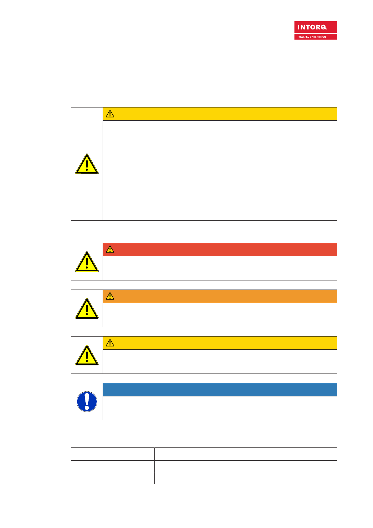
1.3 Safety instructions and notices ............................................................................................................................ 7
1.4 Terminology used................................................................................................................................................. 7
1.5 Abbreviations used............................................................................................................................................... 8
2 Safety instructions................................................................................................................................................... 10
2.1 General safety instructions................................................................................................................................. 10
2.2 Disposal ............................................................................................................................................................. 10
3 Product description ................................................................................................................................................. 11
3.1 Proper and intended usage................................................................................................................................ 11
3.1.1 Standard applications............................................................................................................................ 11
3.2 Layout ................................................................................................................................................................ 11
3.2.1 BFK551.................................................................................................................................................. 11
3.3 Function ............................................................................................................................................................. 12
3.4 Braking and release ........................................................................................................................................... 12
3.5 Project planning notes........................................................................................................................................ 12
4 Technical specifications.......................................................................................................................................... 13
4.1 Possible applications of the Kendrion INTORQ spring-applied brake................................................................ 13
4.2 Characteristics ................................................................................................................................................... 13
4.3 Switching times .................................................................................................................................................. 15
4.4 Friction work / operating frequency.................................................................................................................... 17
4.5 Electromagnetic compatibility............................................................................................................................. 18
4.6 Emissions........................................................................................................................................................... 18
4.7 Labels on product............................................................................................................................................... 19
5 Mechanical installation............................................................................................................................................ 21
5.1 Design of end shield and shaft........................................................................................................................... 21
5.2 Tools .................................................................................................................................................................. 22
5.3 Preparing the installation.................................................................................................................................... 22
5.4 Installing the hub onto the shaft ......................................................................................................................... 23
5.4.1 Mounting the hub with grub screws....................................................................................................... 23
5.4.2 Mounting the hub using a key................................................................................................................ 24
5.5 Mounting the brake ............................................................................................................................................ 24
5.5.1 Mounting the BFK551............................................................................................................................ 24
Kendrion INTORQ | BA 14.0224 | 02/2021 4

6 Electrical installation ............................................................................................................................................... 27
6.1 Electrical connection .......................................................................................................................................... 27
6.1.1 AC switching at the motor – extremely delayed engagement ............................................................... 28
6.1.2 DC switching at the motor – fast engagement....................................................................................... 29
6.1.3 AC switching at mains – delayed engagement...................................................................................... 30
6.1.4 DC switching at mains – fast engagement ............................................................................................ 31
6.1.5 Switching at a supply voltage of 24 V DC.............................................................................................. 32
6.2 Minimum bending radius for the brake connection cable................................................................................... 32
7 Commissioning and operation ............................................................................................................................... 33
7.1 operating range for the Kendrion INTORQ spring-applied brake....................................................................... 33
7.2 Function checks before initial commissioning .................................................................................................... 34
7.2.1 Function check of the brake .................................................................................................................. 34
7.2.2 Release / voltage control....................................................................................................................... 34
7.3 Commissioning................................................................................................................................................... 35
7.4 Operation ........................................................................................................................................................... 35
8 Maintenance and repair........................................................................................................................................... 37
8.1 Wear of spring-applied brakes ........................................................................................................................... 37
8.2 Inspections......................................................................................................................................................... 38
8.2.1 Maintenance intervals............................................................................................................................ 38
8.3 Maintenance....................................................................................................................................................... 38
8.3.1 Checking the components..................................................................................................................... 39
8.3.2 Checking the air gap.............................................................................................................................. 39
8.3.3 Release / voltage................................................................................................................................... 40
8.3.4 Brake replacement ................................................................................................................................ 40
8.4 Spare parts list ................................................................................................................................................... 41
9 Troubleshooting and fault elimination................................................................................................................... 42
Kendrion INTORQ | BA 14.0224 | 02/2021 5

General information
Kendrion INTORQ | BA 14.0224 | 02/2021 6
1 General information
1.1 Using these Operating Instructions
¾
These Operating Instructions will help you to work safely with the spring-applied brake with electro-
magnetic release. They contain safety instructions that must be followed.
¾
All persons working on or with electromagnetically released spring-applied brakes must have the Oper-
ating Instructions available and observe the information and notes relevant for them.
¾
The Operating Instructions must always be in a complete and perfectly readable condition.
1.2 Conventions in use
This document uses the following styles to distinguish between different types of information:
Spelling of numbers Decimal separator Point The decimal point is always used. For ex-
ample: 1234.56
Page reference Underscore, red _____
Reference to another page with additional
information
For example: Using these Operating In-
structions,Page6
Symbols
Wildcard □
Wildcard (placeholder) for options or selec-
tion details
For example: BFK551-□□ = BFK551-05
Notice Important notice about ensuring smooth op-
erations or other key information.

General information
Kendrion INTORQ | BA 14.0224 | 02/2021 7
1.3 Safety instructions and notices
The following icons and signal words are used in this document to indicate dangers and important safety
information:
Structure of safety notices:
CAUTION
Icon
Indicates the type of danger
Signal word
Characterizes the type and severity of danger.
Notice text
Describes the danger.
Possible consequences
List of possible consequences if the safety notices are disregarded.
Protective measures
List of protective measures required to avoid the danger.
Danger level
DANGER
DANGER indicates a hazardous situation which, if not avoided, will result in death or seri-
ous injury.
WARNING
WARNING indicates a potentially hazardous situation which, if not avoided, could result in
death or serious injury.
CAUTION
CAUTION indicates a hazardous situation which, if not avoided, could result in minor or
moderate injury.
NOTICE
Notice about a harmful situation with possible consequences: the product itself or sur-
rounding objects could be damaged.
1.4 Terminology used
Term In the following text used for
Spring-applied brake Spring-applied brake with electromagnetic release
Drive system Drive systems with spring-applied brakes and other drive components

General information
Kendrion INTORQ | BA 14.0224 | 02/2021 8
1.5 Abbreviations used
Letter symbol Unit Designation
FRN Rated frictional force
F N Spring force
I A Current
IHA Holding current, at 20 °C and holding voltage
ILA Release current, at 20 °C and release voltage
INA Rated current, at 20 °C and rated voltage
M4Nm Torque that can be transmitted without slippage occurring (DIN VDE 0580)
MANm Tightening torque of fastening screws
Mdyn Nm Average torque from initial speed to standstill
MKNm Rated torque of the brake, rated value at a relative speed of rotation of 100 rpm
nmax rpm Maximum occurring speed of rotation during the slipping time t3
PHW Coil power during holding, after voltage change-over and 20 °C
PLW Coil power during release, before voltage change-over and 20 °C
PNW Rated coil power, at rated voltage and 20 °C
Q J Quantity of heat/energy
QEJMax. permissible friction energy for one-time switching, thermal parameter of
the brake
QRJ Braking energy, friction energy
QSmax JMaximally permissible friction energy for cyclic switching, depending on the
operating frequency
RNOhms Rated coil resistance at 20 °C
Rzμm Averaged surface roughness
Sh1/h Operating frequency: the number of switching operations evenly distributed
over the time unit
Shue 1/h Transition operating frequency, thermal parameter of the brake
Shmax 1/h Maximum permissible operating frequency, depending on the friction energy
per switching operation
sLmm Air gap: the lift of the armature plate while the brake is switched
sLN mm Rated air gap
sLmin mm Minimum air gap
sLmax mm Maximum air gap
t1ms Engagement time, sum of the delay time and braking torque: rise time
t1 = t11 + t12
t2ms Disengagement time, time from switching the stator until reaching 0.1 Mdyn
t3ms Slipping time, operation time of the brake (according to t11) until standstill

General information
Kendrion INTORQ | BA 14.0224 | 02/2021 9
Letter symbol Unit Designation
t11 ms Delay during engagement (time from switching off the supply voltage to the
beginning of the torque rise)
t12 ms Rise time of the braking torque, time from the start of torque rise until reach-
ing the braking torque
tue s Over-excitation period
U V Voltage
UHV DC Holding voltage, after voltage change-over
ULV DC Release voltage, before voltage change-over
UNV DC Rated coil voltage; in the case of brakes requiring a voltage change-over,
UN equals UL

Safety instructions
Kendrion INTORQ | BA 14.0224 | 02/2021 10
2 Safety instructions
2.1 General safety instructions
¾
Never operate Kendrion INTORQ components when you notice they are damaged.
¾
Never make any technical changes to Kendrion INTORQ components.
¾
Never operate Kendrion INTORQ components when they are incompletely mounted or incompletely
connected.
¾
Never operate Kendrion INTORQ components without their required covers.
¾
Only use accessories that have been approved by Kendrion INTORQ.
¾
Only use original spare parts from the manufacturer.
Keep the following in mind during the initial commissioning and during operation:
¾
Depending on the degree of protection, Kendrion INTORQ components may have both live (voltage
carrying), moving and rotating parts. Such components require appropriate safety mechanisms.
¾
Surfaces can become hot during operation. Take appropriate safety measures (to ensure contact/
touch protection).
¾
Follow all specifications and information found in the Operating Instructions and the corresponding
documentation. These must be followed to maintain safe, trouble-free operations and to achieve the
specified product characteristics.
¾
The installation, maintenance and operation of Kendrion INTORQ components may only be carried out
by qualified personnel. According to IEC 60364 and CENELEC HD 384, skilled personnel must be
qualified in the following areas:
– Familiarity and experience with the installation, assembly, commissioning and operation of the
product.
– Specialist qualifications for the specific field of activity.
– Skilled personnel must know and apply all regulations for the prevention of accidents, directives,
and laws relevant on site.
2.2 Disposal
The Kendrion INTORQ components are made of various differing materials.
¾
Recycle metals and plastics.
¾
Ensure professional disposal of assembled PCBs according to the applicable environmental regula-
tions.

Product description
Kendrion INTORQ | BA 14.0224 | 02/2021 11
3 Product description
3.1 Proper and intended usage
3.1.1 Standard applications
Kendrion INTORQ components are intended for use in machinery and facilities. They may only be used
for purposes as specified in the order and confirmed by Kendrion INTORQ. The Kendrion INTORQ com-
ponents may only be operated under the conditions specified in these Operating Instructions. They may
never be operated beyond their specified performance limits. The technical specifications (refer to Techni-
cal specifications,Page13) must be followed to comply with the proper and intended usage. Any other
usage is consider improper and prohibited.
3.2 Layout
This chapter describes the design and functionality of the INTORQ BFK551 spring-applied brake.
3.2.1 BFK551
A
B
CDE
F
G
J
H
I
Fig.1: Design of an INTORQ BFK551 spring-applied brake (flange-side mounting)
AStator BConnection cable CFastening screw
DClamping disc EArmature plate FHub
GSpring HCoil IRotor
JFlange

Product description
Kendrion INTORQ | BA 14.0224 | 02/2021 12
3.3 Function
This brake is an electrically releasable spring-applied brake with a rotating brake disk (rotor) that is
equipped on both sides with friction linings. In its de-energized state, the rotor is clamped with braking
force applied by pressure springs between the armature plate and a counter friction surface. This corre-
sponds to a fail-safe functionality.
The brake torque applied to the rotor is transferred to the input shaft via a hub that has axial gear teeth.
The brake can be used as a holding brake, as a service brake, and as an emergency stop brake for high
speeds.
The asbestos-free friction linings ensure a safe braking torque and low wear.
To release the brake, the armature plate is released electromagnetically from the rotor. The rotor, shifted
axially and balanced by the spring force, can rotate freely.
3.4 Braking and release
During the braking procedure, the pressure springs use the armature plate to press the rotor (which can
be shifted axially on the hub) against the friction surface. The braking torque is transmitted between the
hub and the rotor via gear teeth.
When the brakes are applied, an air gap (sL) is present between the stator and the armature plate. To re-
lease the brake, the coil of the stator is energized with the DC voltage provided. The resulting magnetic
flux works against the spring force to draw the armature plate to the stator. This releases the rotor from the
spring force and allows it to rotate freely.
3.5 Project planning notes
¾
When designing a brake for specific applications, torque tolerances, the limiting speeds of the rotors,
the thermal resistance of the brake and the effects of environmental influences must all be taken into
account.
¾
The brakes are dimensioned in such a way that the specified rated torques are reached safely after a
short run-in process.
¾
Since the material properties of the friction linings are subject to fluctuations and as a result of different
environmental conditions, deviations from the specified braking torque are possible. This has to be
taken into account by appropriate dimensioning of the tolerances. Increased breakaway torque can oc-
cur in particular as an result of long standstill periods in humid environments with variing temperatures.
¾
If the brake is used as a pure holding brake without dynamic load, the friction lining must be reacti-
vated regularly.

Technical specifications
Kendrion INTORQ | BA 14.0224 | 02/2021 13
4 Technical specifications
4.1 Possible applications of the Kendrion INTORQ spring-applied brake
¾
Degree of protection:
– The brake has IP00 protection. Because of the many ways of using the brake, it is necessary to
verify the functionality of all mechanical components under the corresponding operating conditions.
¾
Ambient temperature:
– -20 °C to +40 °C (Standard)
4.2 Characteristics
Size Rated brake torque at
Δn=100 rpm
Air gap Moment of inertia
of rotor
Weight of brake
MKSLN
1) SLmax JRotor
2)
[Nm] [mm] [mm] [kg mm2] [kg]
01 0.24 0.15 +0.08/-0.05 0.28 0.369 0.14
02 0.5 1.24 0.24
03 0.5
0.15 +0.1/-0.05
0.4 2.794 0.32
1 0.3
04 1 0.4 7.719 0.45
2 0.3
05 2 0.4 13.964 0.68
4 0.3
Tab.1: General data
1) The air gap in the default (delivered) condition results from the total tolerance of the individual parts after the brake
is mounted. When checking the air gap, the feeler gauge must not be inserted deeper than 15 mm into the air gap
between the armature plate and the stator.
2) If a hub is used, its moment of inertia must also be taken into account.
Notice
The specified rated torque is achieved up to the maximum speed of Δn0max = 5000 rpm.

Technical specifications
Kendrion INTORQ | BA 14.0224 | 02/2021 14
Size Outer diameter Screw hole circle Minimum thread depth in
motor end shield
Tightening torque
Diameter (Ø) Thread1) MA
[mm] [mm] [mm] [Nm]
01 37 32 3x M2.5 4.5 0.7
02 47 40
3x M3 6 1.303 56 48
04 65 58
05 75 66 3x M4 7 3
Tab.2: Mounting data
1) Fastening screws (socket-head cap screws according to DIN EN ISO 14580) are included in the scope of delivery
CAUTION
Functional incapacity of the brake
It is very important to comply with the minimum thread depth of the end shield (refer to the
Mounting data,Page14 table).
If the required thread depth is not maintained, the fastening screws may run onto the
thread root. This has the effect that the required pre-load force is no longer established –
the brake is no longer securely fastened!
The material of the end shield must have a tensile strength of Rm > 250 N/mm2 !
Size Electrical power
PN
Rated voltage
UN
Rated current
IN
Coil resistance
RN
[W] [V] [A] [Ω] ±8%
01 4.9 24 0.20 117.6
02
6.2 24 0.26 92.90
6.4 103 0.06 1658
5.9 205 0.03 7123
03
8.3 24 0.35 69.40
8.2 103 0.08 1294
8.0 205 0.04 5223
04
10.9 24 0.45 52.84
10.8 103 0.10 982.3
10.5 205 0.05 4002
05
12.4 24 0.52 46.45
12.2 103 0.12 869.6
13.1 205 0.06 3208
Tab.3: Coil data

Technical specifications
Kendrion INTORQ | BA 14.0224 | 02/2021 15
4.3 Switching times
The operating times listed here are guide values which apply to DC switching with rated air gap sLN, warm
coil and standard characteristic torque. The given operating times are average values and subject to varia-
tions. The engagement time t1 is approximately 8 to 10 times longer for AC switching.
t
t
M
t2
t12
t11
t1
Mdyn
U
0.1Mdyn
Fig.2: Operating/switching times of the spring-applied brakes
t1Engagement time t11 Delay time during engagement
t2Disengagement time (up to M = 0.1 Mdyn)t12 Rise time of the braking torque
Mdyn Braking torque at a constant speed of rotation UVoltage
Size Rated brake
torque at
Δn=100 rpm
MK
1)
QE
1) Shue Operating times 2) Maximum
speed
Δnmax
DC-side engagement Disengaging
t11 t12 t1t2
[Nm] [J] [1/h] [ms] [ms] [ms] [ms] [rpm]
01 0.24 200 160 5 7 12 22 5000
02 0.5 400 125 6 10 16 25 5000
03 0.5 800 100 16 17 33 13 5000
1 800 100 7 13 20 28 5000
04 1 1200 90 18 24 42 20 5000
2 1200 90 7 16 23 31 5000
05 2 1800 80 19 30 49 26 5000
4 1800 80 8 19 27 34 5000
Tab.4: Switching energy - operating frequency - operating times
1) The maximum permissible friction energy QE relates to the standard friction lining.
2) These operating times are specified for usage of coils with a connection voltage of 24 V DC at sLN and 0.7 IN.

Technical specifications
Kendrion INTORQ | BA 14.0224 | 02/2021 16
Engagement time
The transition from a brake-torque-free state to a holding-braking torque is not free of time lags.
For emergency braking, short engagement times for the brake are absolutely essential. The DC-side
switching in connection with a suitable spark suppressor must therefore be provided.
Engagement time for AC-side switching: The engagement time is significantly longer (approx. 10 times
longer).
NOTICE
Connect the spark suppressors in parallel to the contact. If this is not admissible for safety
reasons (e.g. with hoists and lifts), the spark suppressor can also be connected in parallel
to the brake coil.
¾
If the drive system is operated with a frequency inverter so that the brake will not be de-energized be-
fore the motor is at standstill, AC switching is also possible (not applicable to emergency braking).
¾
The specified engagement times are valid for DC switching with a spark suppressor.
– Circuit proposals: refer to DC switching at mains – fast engagement,Page31.
Notice
Spark suppressors are available for the rated voltages.
Disengagement time
The disengagement time is the same for DC-side and AC-side switching. The specified disengagement
times always refer to control using Kendrion INTORQ rectifiers and rated voltage.

Technical specifications
Kendrion INTORQ | BA 14.0224 | 02/2021 17
4.4 Friction work / operating frequency
BG 05
BG 04
BG 03
BG 02
BG 01
10 100
1
10000
10
100
1000
11000
Reibarbeit QR[J]
Schalthäufigkeit Sh[h-1]
10000
10000
1000
100
10 110 100 1000 10000
Friction work Q [J]
R
Operating frequency Sh[h ]
-1
Size 05
Size 04
Size 03
Size 02
Size 01
Fig.3: Friction work as a function of the operating frequency
–Shue
–
1
QR
QE
Shmax
In
=
– e
1
QSmax QE
=
–Shue
Sh
The permissible operating frequency Shmax depends on the friction work QR (refer to Figure Friction work /
operating frequency,Page17). At a pre-set operating frequency Sh, the permissible friction work is QSmax.
Notice
With high speeds of rotation and switching energy, the wear increases, because very high
temperatures occur at the friction surfaces for a short time.

Technical specifications
Kendrion INTORQ | BA 14.0224 | 02/2021 18
4.5 Electromagnetic compatibility
Notice
The user must ensure compliance with EMC Directive 2014/30/EC using appropriate controls
and switching devices.
NOTICE
If a Kendrion INTORQ rectifier is used for the DC switching of the spring-applied brake
and if the switching frequency exceeds five switching operations per minute, the use of a
mains filter is required.
If the spring-applied brake uses a rectifier of another manufacturer for the switching, it
may become necessary to connect a spark suppressor in parallel with the AC voltage.
Spark suppressors are available on request, depending on the coil voltage.
4.6 Emissions
Heat
Since the brake converts kinetic energy and electrical energy into heat, the surface temperature varies
considerably, depending on the operating conditions and possible heat dissipation. A surface temperature
of 130 °C may be reached under unfavorable conditions.
Noise
The loudness of the switching noise during engaging and disengaging depends on the air gap "sL" and the
brake size.
Depending on the natural oscillation after installation, operating conditions and the state of the friction sur-
faces, the brake may squeak during braking.

Technical specifications
Kendrion INTORQ | BA 14.0224 | 02/2021 19
4.7 Labels on product
There is a packaging label on the package. The name plate is glued to the lateral surface of the brake.
Fig.4: Name plate (example)
Kendrion INTORQ Manufacturer
BFK551-01 Type (refer to Product key,Page3 )
24 V DC Rated voltage
4.9 W Rated power
No. 33008121 ID number
0.24 NM Rated torque
05.02.21 Date of manufacture
Data matrix code
CE mark
UL mark

Technical specifications
Kendrion INTORQ | BA 14.0224 | 02/2021 20
Fig.5: Packaging label
Kendrion INTORQ Manufacturer
33008121 ID number
BFK551-01 Type (refer to Product key,Page3 )
Bar code
SPRING-APPLIED BRAKE Designation of the product family
24 V DC Rated voltage
0.24 NM Rated torque
10 pc. Qty. per box
4.9 W Rated power
05.02.21 Packaging date
Anti-rust packaging: keep friction surface free of
grease! Addition
CE mark
This manual suits for next models
1
Table of contents
Other Kendrion Spring Applied Brake manuals