Easy Startup
To setup the Optidrive communication address
By default, the Optipad will try to communicate with the drive that has Address 1 in the network after powering up for the first time.
The Optipad will display “Scanning for Drive 01.” after power up, which indicates that the Optipad is searching for the drive with the
correct drive address in the network. Once the drive has been found, the message “Load...” will be displayed on the Optipad, which
indicates that the Optipad is reading the configuration information from the drive. Usually it will take 1~2 seconds for the Optipad to
read this information. After the data has been loaded, the Optipad will display the drive real time status.
NOTE In the case where the keypad is connected to a drive where the network address is not 1, the following steps can be used to
set the address of the drive
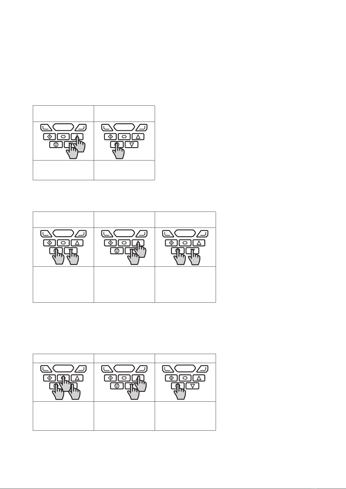
Select Drive Address
01
Select Drive Address
01
Use the Up and Down
arrows to select the
address.
Press the Stop button once
address has changed to
match the connected drive.
Working with Multiple Drive Networks
When the Optipad is used on networks with multiple drives, the user can change the drive address to set up communication with
another drive in the same drive network at anytime.
Select Drive Address
xx
Select Drive Address
xx
Select Drive Address
xx
Briefly press the Stop and
Down keys to display the
above message.
Use the Up and Down
arrows to select the
desired address.
After selecting the new
address, press the Stop
and Down keys to
establish communications
with the drive.
NOTE For detailed parameter listing and functional setup, please refer to the corresponding Optidrive user guide
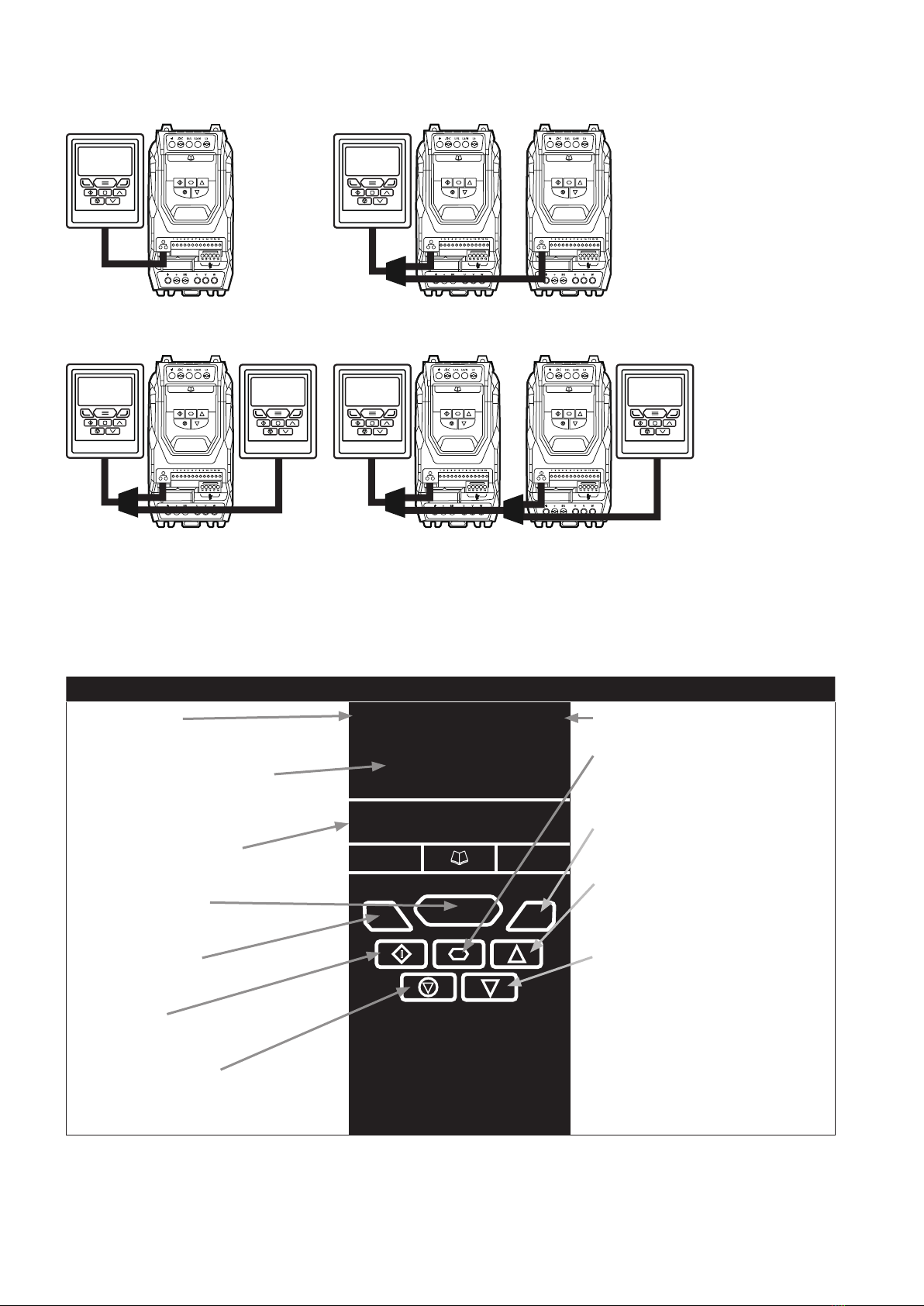
Networks with 2 Optipads connected
A maximum of 2 Optipads can be connected within the same drive network to communicate with the same drive or different drives.
When using two Optipads simultaneously on a network, the user must change the Optipad Device Number on the second Optipad to
ensure correct operation. All Optipad units are set to Device Number 1 by default.
Select OptiPad ID xx Select OptiPad ID xx Select OptiPad ID xx
To change the Device
Number, press the
Navigate, Stop and
Down keys together.
Use the Up and Down
arrows to select the
desired Optipad Numer
(1 or 2).
Press the Stop key
to return ro normal
operation.
NOTE Once the User has set the Optipad as Device Number 2, OptiTools software cannot be used on the same drive network.
The Optipad Device Address should only be changed to 2 if 2 Optipad units are connected on a network. An Optipad with Device
Number 1 must always be present for the network to function correctly.
4| Optipad TFT Remote Keypad IP55 User Guide | Version 1.02 www.invertekdrives.com