CONTENTS
SPECIFICATIONS
.........................................................
2
FEATURES
................................................................
3
PRODUCT OVERVIEW
...................................................
3
SAFETY INSTRUCTIONS
.................................................
4
INSTALLATION
...........................................................
5
TOOLS REQUIRED
.....................................................................
5
OVERVIEW OF STEPS
..................................................................
5
STEP ONE - CHECK BOX CONTENTS
..................................................
5
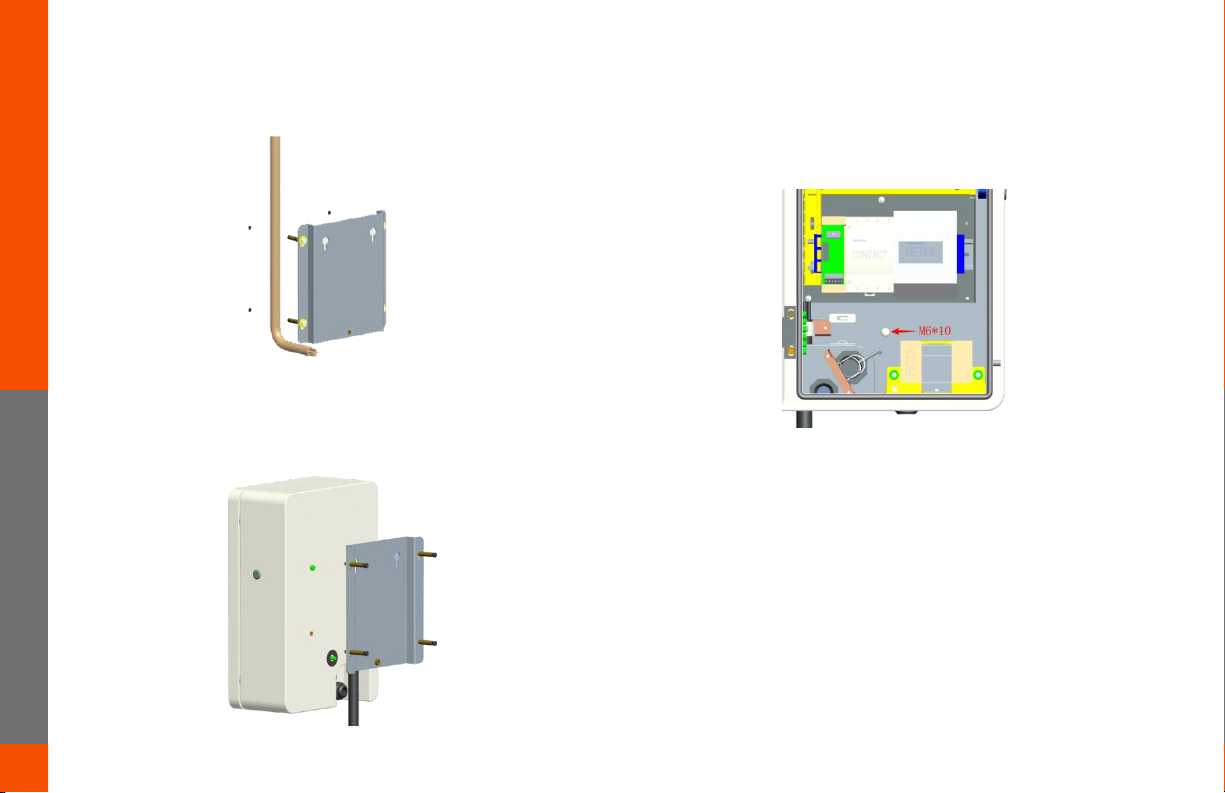
STEP TWO – CONCRETE ANCHORING
............................................
6
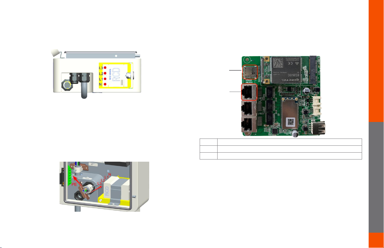
STEP THREE – POWER CABLE WIRING
...............................................
7
STEP FOUR – INTERNET CONNECTION
.................................................
7-8
STEP FIVE – VERIFY THE INSTALLATION
..................................................
8
STEP SIX - SECURE COVER
............................................................
8
LCD DISPLAY DETAILS
........................................................
9-11
TROUBLESHOOTING
............................................................
12
MAINTENANCE AND REPAIR
..................................................
12
For information on how to charge your electric vehicle, refer to the documentation
provided with your vehicle.
IMPORTANT !
READ THIS ENTIRE DOCUMENT BEFORE INSTALLING
OR USING THE CHARGER. FAILURE TO DO SO OR TO
FOLLOW ANY OF THE INSTRUCTIONS AND WARNINGS
IN THIS DOCUMENT CAN RESULT IN FIRE, ELECTRICAL
SHOCK, SERIOUS INJURY OR DEATH.
THE CHARGER MUST BE INSTALLED BY A QUALIFIED
ELECTRICIAN.
THE ENTIRE INSTALLATION MUST COMPLY WITH THE
LATEST BS 7671 REGULATIONS.