manuals.online logo
Brands
  1. Home
  2. •
  3. Brands
  4. •
  5. Ioline
  6. •
  7. Plotter
  8. •
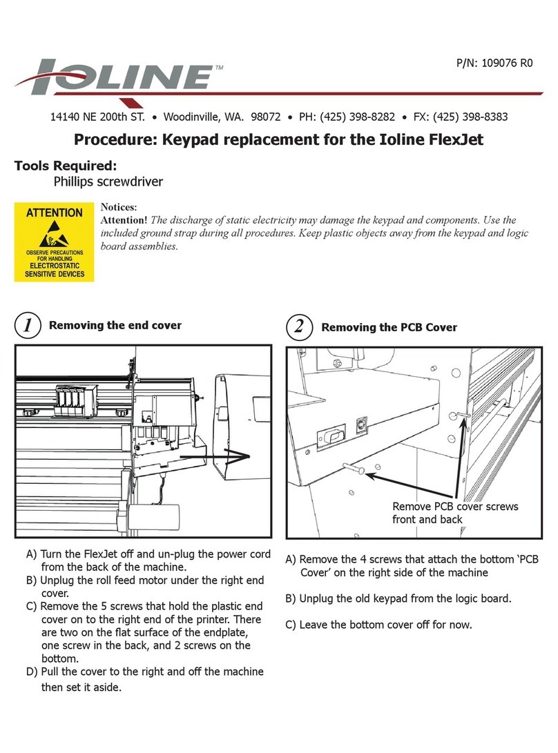
  9. Ioline FlexJet User manual

Ioline FlexJet User manual

Other manuals for FlexJet

4

Other Ioline Plotter manuals

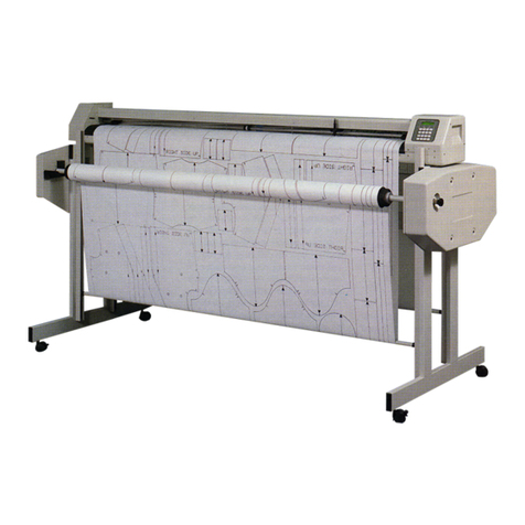
Ioline 600H Service manual

Ioline

Ioline 600H Service manual

Ioline Ae Guide

Ioline

Ioline Ae Guide

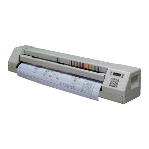
Ioline FlexJet E Instruction sheet

Ioline

Ioline FlexJet E Instruction sheet

Ioline Stylist 2000 User manual

Ioline

Ioline Stylist 2000 User manual

Ioline Summit User manual

Ioline

Ioline Summit User manual

Ioline Signature5000 User manual

Ioline

Ioline Signature5000 User manual

Ioline FJ8 User manual

Ioline

Ioline FJ8 User manual

Ioline Signature 5000 Service manual

Ioline

Ioline Signature 5000 Service manual

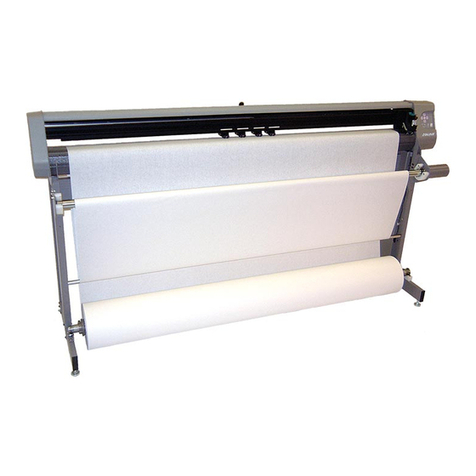
Ioline FlexJet User manual

Ioline

Ioline FlexJet User manual

Ioline FlexJet User manual

Ioline

Ioline FlexJet User manual

Ioline Summit User manual

Ioline

Ioline Summit User manual

Popular Plotter manuals by other brands

MUTOH Kona 760 Service manual

MUTOH

MUTOH Kona 760 Service manual

HP 7475a Service manual

HP

HP 7475a Service manual

Vulcan-Hart FC-500VC user manual

Vulcan-Hart

Vulcan-Hart FC-500VC user manual

Roland TrueVIS VG-640 Supplemental manual

Roland

Roland TrueVIS VG-640 Supplemental manual

MIMAKI CF2 Series Operation manual

MIMAKI

MIMAKI CF2 Series Operation manual

Roland VersaUv LEF - 12i troubleshooting guide

Roland

Roland VersaUv LEF - 12i troubleshooting guide

Roland VersaCamm SP-540V user manual

Roland

Roland VersaCamm SP-540V user manual

Seiko I Infotech LP-1020 user guide

Seiko I Infotech

Seiko I Infotech LP-1020 user guide

HP 7470A Interfacing and programming manual

HP

HP 7470A Interfacing and programming manual

Roland VersaUV LEF-200 Tutorial

Roland

Roland VersaUV LEF-200 Tutorial

ENCAD T-200 Service manual

ENCAD

ENCAD T-200 Service manual

GRAPHTEC CE6000-120AP user manual

GRAPHTEC

GRAPHTEC CE6000-120AP user manual

HP Designjet 330 user guide

HP

HP Designjet 330 user guide

Furuno RP-17 Operator's manual

Furuno

Furuno RP-17 Operator's manual

MIMAKI CFL-605RT Operation manual

MIMAKI

MIMAKI CFL-605RT Operation manual

HP 7470A Operator's manual

HP

HP 7470A Operator's manual

Skycut D Series user manual

Skycut

Skycut D Series user manual

Furuno GP-3500 installation manual

Furuno

Furuno GP-3500 installation manual

manuals.online logo
manuals.online logoBrands
  • About & Mission
  • Contact us
  • Privacy Policy
  • Terms and Conditions

Copyright 2025 Manuals.Online. All Rights Reserved.

14140 NE 200th St. Woodinville, WA. 98072 PH: (425) 398-8282 FX: (425) 398-8383
FlexJet Logic Board replacement
Tools Required:
Phillips head screwdriver
5/32” Allen wrench.
2. Remove the right side cover of the machine
(There are a total of 5 screws. 2 black phillips screws on the end
plate, One silver phillips screw on the back, and two silver phil-
lips screws on the bottom.)
3. Remove 6 of 8 screws that hold the printer to the
stand on both sides. See drawing below for the right
screws to remove.
CAUTION: The printer is VERY heavy. Always stand
behind the machine while performing this task.
1. Unplug the take-up motor cable from the bottom of
the machine. Unplug the power and serial cable.
4. Stand behind the machine and lift it by the rear bar
holding your hands 6” from the end plates. Roll the
machine forward on the stand until it comes to rest in
the forward position.
Remove these screws
ONLY
DO NOT REMOVE!
Take-up motor cable
P/N: 108497 R2
6. Make sure you are grounded with a static ground-
ing strap (Included with a new logic board, DO NOT
remove the new logic board from the packaging).
Remove the logic board cover. Note: Carefully unplug
the take-up connector from the logic board before
completely removing the cover.
7. Mark the plugins as needed and carefully unplug
the connections from the board. Remove the 6 silver
phillips screws holding the board in the machine. Sup-
port the logic board with hand when removing the last
screw to prevent it from falling onto the fl oor.
5. Remove the 4 phillips screws that hold the logic
board cover on.
Cover screws (Rear)
8. Pull the bottom of the board out fi rst. Then pull the
PCB away from the rear so the serial port connection
is not damaged.
NOTE: Don’t force it.
Screws
WARNING: When removing the new logic
board from the packaging make sure you
have the Static Grounding Strap on cor-
rectly. If there is a static discharge to the
new board it may not function properly.
9. Remove the new logic board from it’s packaging.
11. Plug in all the wire connections to the board. Make
sure the connectors are not off by a pin (See below).
Right Wrong
12. Install the board cover making sure to plug in the
take-up wire connections to the board first. Make sure
there are no wires or cables pinched between the cover
and the body.
13. Install the right side plastic cover.
10. Install the new logic board into the machine. Care-
fully insert the serial port end into the holes in the
metal bracket first. Tighten the 6 phillips screws that
hold the board in making sure not to overtighten them.
14. Connect the power and serial cables.
15. Test the machine for proper functioning. Press the
arrows on the keypad to make sure all directions are
working.
16. If problems arise call Ioline Tech Support.