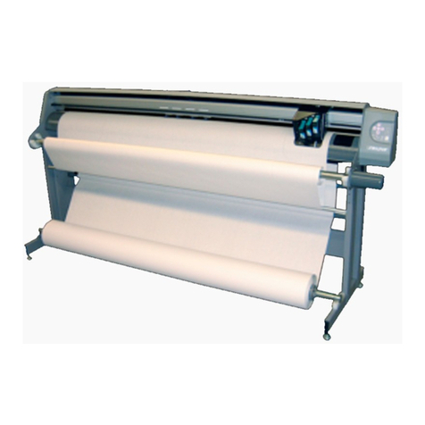
Ioline Stylist 2000 User manual

Technical Bulletins Stylist 2000 & LP 7200
TABLE OF CONTENTS
Dimensional Calibration
Frame Gap
Frame Sensor Adjustment
Rollfeed Parameters
Y-Axis Registration

Technical Bulletin Dimensional Calibration/Stylist 2000 & LP 7200
All pen plotters have deviations in accuracy due to paper thickness, humidity, or
temperature. By using the microcalibration feature, you can adjust the variance to
within 0.05%. The microcalibration should be performed each time you use a different
type of paper.
To calibrate your Stylist 2000 or LP 7200:
1. Load paper.
2. From the keypad set the lower left and size, then press (F3) “Action” (F2) “Tests”
(F4) “Calplot”.
3. Two sets of connected lines are marked off in inches and centimeters.
4. Exit to the main menu of the keypad.
5. Remove the paper from the plotter and measure the distance between any two
marks in both the x and y directions. The x direction is always the paper motion
and the y direction is always the pen motion. Example: Measure the distance
between the 1st and 21st mark in the x direction. The plotter assumes the nearest whole
inch (or cm) as the goal.
6. If the marks measure 20.905 inches, on the keypad press (F4) “Setup” (F1)
“Adjust” (F3) “Sizing” (F1) Calibrate. The following message will appear on the
keypad LCD : Enter X Integer
Portion = ?
7. To enter 20.905 inches, press “20” “Enter”. “Enter” in this case places the
decimal point. The following message will appear on the keypad LCD :
Enter Y Decimal
Portion = ?
8. Press “905” “Enter”. After you have pressed “Enter” the following message will
appear on the keypad LCD:
If 20.905000
Correct<ENTER>

9. If the value you have entered is correct, press the “Enter” key to set the x
measurement.
10. Press “Enter” to <Power Up Default>.
11. Follow steps 7 & 8 to set the y coordinate.
12. Calibration is complete.

Technical Bulletin Frame Gap/Stylist 2000 & LP 7200
If you are experiencing a gap between frames, try the following to solve:
1. Level and align the plotter (See chapter 8 of your Guide to Operations "Aligning
the Plotter").
2. Review paper loading. Ensure paper is taught when attached to the take-up
shaft.
3. Remove any paper build up on the grit shaft with a stiff bristled nylon brush.
Paper build up will cause the paper to slip under the chart wheels.
4. Chart wheel placement is crucial. Position each chart wheel pair in 2’ from the
edge of the paper.
5. Remove any foreign matter from the chart wheels that may hinder them from
rotating freely.
6. Reposition the chart wheels over an area of the grit shaft that’s had minimal use
in order to grip the paper better.
7. Ensure the dancer bars are not sticking at the top of the guide, which could
cause the paper to become unbalanced.
8. Paper Quality. Ioline recommends using 35 lb. Bond paper for optimal
performance.
9. Clean the sensor lens using a cotton swab and isopropyl alcohol.
10. Adjust the focal point of the sensor.
11. Use only black ink pens to allow the sensor to pick up the frame mark more
consistently.


Technical Bulletin Frame Sensor Adjustment/Stylist 2000 & LP 7200
1. Turn the sensors vertical height adjustment screw clockwise; lowering it to within
1/8 inch (1/4 cm) of the paper.
2. Select the media size (see page 6 - 3 of your Guide to Operations).
From the keypad main menu:
3. Press (F3) “Action”
4. Press (F2) “Tests”
5. Press (F4) “SensTst”
6. Press (F1) “Mark”
7. The plotter should then draw a one-inch mark, at the paper edge.
8. Press (F4) “Scan”
9. Turn the adjustment screw counterclockwise until the beep sounds each time the
mark passes under the sensor.
10. Start counting turns of the screw, and continue raising the sensor until the beep
is not heard any more.
11. Note the number of turns counted, divide that number by two, and turn the
screw clockwise that many turns.
12. The sensor should now be in the middle of the focal range.

Technical Bulletin Rollfeed Parameters/Stylist 2000 & LP 7200
Rollspd
When this option is selected, the user is prompted to enter a new Slow Speed and a
new High Speed. These values are the low and high power settings applied to the
rollfeed motor during frame advances and loop feeds. First, the rollfeed power is set
to the low setting to roll up the front loop. When the paper is taught between the take
up roll and the gritshaft, the power is increased to the high setting. The slow power to
start to move the gritshaft and the frame advance stops after the paper is taught. It
should be decreased only if the paper snaps hard when it becomes taught. The high
setting should not have to be changed.
Slow Speed: Default = 50 Range = 1 to 99 (power setting)
High Speed: Default = 90 Range = 1 to 99 (power setting)
Gritshaft
When this option is selected, the user is prompted to enter a new Variable. This value
is proportional to the power setting applied to the gritshaft motor during frame
advances and loop feeds. During a frame advance or loop feed, the rollfeed motor
needs to do all the pulling off the back roll. Power is applied to the gritshaft motor
only to help the rollfeed motor turn. This value should be increased only if the rollfeed
motor stalls and the frame advances fail to complete. It should be decreased only if
the gritshaft gets ahead of the rollfeed. That is, a front loop appears (the paper is not
taught) between the take up roll and gritshaft when paper is being pulled onto the
take up roll.
Variable: Default = 20 range = 1 to 50 (power setting)
XRtspd
When this option is selected, the used is prompted to enter a new XRtspd. This value
is the maximum speed the gritshaft will go when it returns to lower left at the end of a
frame advance or loop feed. The speed will be the lower of XRtspd and the current
speed. This value should not have to be changed.
XRtspd: Default = 20 Range = 1 to 20 ips
AloneX
When this option is selected, the user is prompted to enter a new AloneX speed. This
value is the initial power setting applied to the gritshaft motor to overcome friction so
the rollfeed motor can start to turn it. It is not enough power to start turning the
gritshaft by itself. This value should be decreased only if the gritshaft starts moving
before the paper is taught (rollfeed motor has not pulled the entire front loop). This
value should be increased only if the rollfeed motor does not have enough power to

start to move the gritshaft and increasing the Rollspd slow speed causes excessive
snapping of the paper.
AloneX Spd: Default = 20 Range = 1 to 40 (power setting)

Technical Bulletin Y-axis Registration/Stylist 2000 & LP 7200
If you are experiencing y-axis registration problems, check the following:
1. Worn or loose y-axes drive belt. You can measure the y belt tension by moving
the carriage all the way to the right end plate. The y belt should be firm and taut,
but not stretched. Using a spring force gauge, measure the belt tension from the
center of the machine, by deflecting the belt from its natural position
approximately 1/8 inch with 180-220 grams of force applied.
2. Worn or loose y-axis transmission timing belt.
3. Loose or worn pulley on y-axis transmission. Check all pulley set screws.
4. Pen is seated properly into the pen flange.
5. Loose pen jaw.
This manual suits for next models
1
Other Ioline Plotter manuals

Ioline
Ioline Summit User manual

Ioline
Ioline FlexJet User manual

Ioline
Ioline Signature5000 User manual

Ioline
Ioline Summit User manual

Ioline
Ioline FlexJet User manual

Ioline
Ioline FJ8 User manual

Ioline
Ioline 600H Service manual

Ioline
Ioline FlexJet User manual

Ioline
Ioline FlexJet E Instruction sheet

Ioline
Ioline Ae Guide