Ioline Ae Guide

Copyright © 2000, Ioline Corporation, All Rights Reserved
Printed in the United States of America
PN 107027 R1
November, 2000
All Trademarks Are The Property Of Their Respective Owners
Using Your
Ae Apparel Plotter

2
Ioline
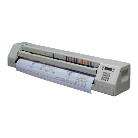
A. Pinchwheel
B. Drive Shaft Marker
C. Carriage
D. Platen
E. Sensor (600Ae only)
F. Carriage Rail
G. Pinchwheel Lever
H. Keypad
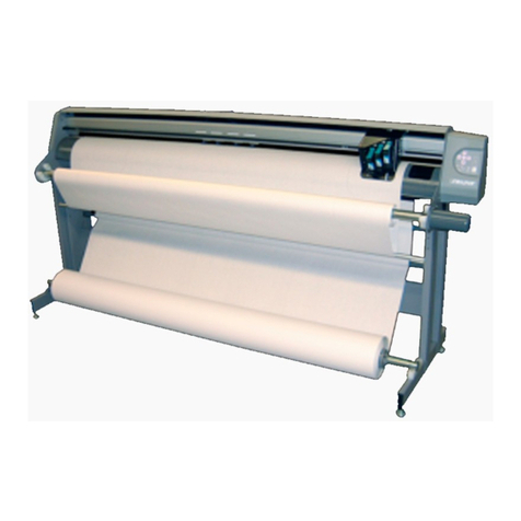
Figure 1. The Ioline Model 600Ae Plotter.
DB E A
HG
F
C

3
Ioline
TABLE OF CONTENTS
SAFETY AND PRECAUTIONS ................................ 4
THE IOLINE AE APPAREL PLOTTER .................... 4
HowTheIolinePlotterWorks .............................. 5
INSTALLATION ........................................................ 6
UnpackthePlotter .............................................. 6
AssembletheStand ........................................... 6
AttachthePlottertotheStand............................. 6
ConnectthePlottertotheComputer ................... 6
PowerOn ........................................................... 6
InstallingtheIolineControlCenter ....................... 6
OPERATION ............................................................. 7
Keypad Controls .................................................. 7
The Ioline Control Center .................................... 9
ChangingSystemSettings ............................... 10
MenuBarFeatures........................................... 10
ScreenMenuOptions ....................................... 10
Plotting a Marker ................................................ 12
GeneralGuidelines........................................... 12
InstallingaPen ................................................. 12
PowerOn ......................................................... 12
Paper ............................................................... 12
GuidelinesforPlottingPens.............................. 12
Loadingthe Feed Roll ...................................... 13
LoadingtheTake-Up Shaft ............................... 14
Feeding Paper ................................................. 15
Taping PapertotheTake-Up Shaft.................... 16
Taping Paper(OptionalMethod) ....................... 17
PositioningthePinchwheels ............................. 17
InserttheDancerBars ...................................... 18
Setan Origin .................................................... 18
Sending Plot Files ............................................ 19
Pausinga Marker Plot ...................................... 19
Cancelinga Marker Plot ................................... 19
RemovingMarkersfromtheTake-Up Shaft ....... 20
ReattachPapertotheTake-Up Shaft ................ 21
ROUTINE MAINTENANCE .................................... 22
CleaningtheDriveShaft ................................... 22
Calibration........................................................ 22
CleaningthePlaten .......................................... 23
CleaningtheSupport Blocks............................. 23
COMMUNICATION TESTING................................. 24
CommunicationTest ......................................... 24
Testing thePlotterSerialPort............................ 24
Testing theComputerSerialPort ...................... 24
TROUBLESHOOTING ........................................... 25
GeneralProblems ............................................ 25
PlottingQualityProblems.................................. 25
Loss ofRegistrationBetweenFrames .............. 27
Tracking ........................................................... 27
PoorLine Quality .............................................. 27
Error Messages................................................ 28
LED Codes ...................................................... 29
Testing theFrameSensor................................. 30
END NOTES ........................................................... 31
GettingHelp ..................................................... 31
TheFCCWants YoutoKnow... ......................... 32
Your Comments Are Requested........................ 32
CustomerService............................................. 32
Limitof Liability Statement................................ 32
GLOSSARY ............................................................ 33
INDEX ..................................................................... 35

4
Ioline
SAFETY AND PRECAUTIONS
The plotter has many fast moving components. Please read and follow these
safety guidelines before beginning operation of the plotter.
• Do not try to repair the machine without factory authorization. Only quali-
fied service personnel should attempt any disassembly or access to inter-
nal components. If external mechanical adjustments are necessary, turn
off the plotter and disconnect it from all power sources (both the com-
puter and the wall outlet).
• Be careful with hair, jewelry, or loose clothing near the plotter. They can
become caught in the mechanical parts.
• Never move the carriage by hand. Use the Arrow keys and let the ma-
chine do it.
• Keep hands away from the carriage when the plotter is in operation. The
carriage will automatically move to its right end position when the power
is turned on.
• Be careful when lifting the plotter. Hold the bottom surfaces of the plotter
to lift or move it.
• Keep fingers away from the drive shaft when the plotter is in operation.
THE IOLINE AE APPAREL PLOTTER
Thank you for purchasing an Ioline plotter.
This manual contains instructions and guidelines for setting up, operating
and maintaining the Ioline plotter models 600Ae, 28Ae and Stylist Ae. The
model 600Ae uses a frame sensor to allow ultra long plotting up to 600 yards.
Models 28Ae and Stylist Ae do not use a sensor for frame correction which
limits plotting to 42 yards. The following components are needed to create
plots:
• An Ioline plotter that is installed according to the directions in the Quick
Start Guide.
• A computer system that is properly installed and has a functioning serial
port.
• Design software loaded into the computer according to the installation
instructions. Note: The design software must output plot files in HPGL
7475/7596 or DM/PL format.
• Plotting media and a pen that are within the guidelines stated in the
Operation chapter.
• The Ioline Control Center software. This software is not required but
allows adjustment of plotter settings and can help optimize performance.
The Ioline Control Center will only run on the Windows 95/98/NT oper-
ating systems. Most design software provides drivers for Ioline plotters.
Contact Ioline customer service if you need assistance with drivers.

5
Ioline
HowThe Ioline PlotterWorks
Media and pen motion are combined to create vector plots. Files are sent to the plotter via a serial connection with a computer or file server. When a file is sent to the plotter
the electronic logic system translates the vectors into instructions for the X axis (paper motion) andY axis (pen motion) motors and uses feedback to ensure plot accuracy.
Long plots are accomplished by breaking the plot file into frame segments and rolling the completed frames onto a take-up shaft. The model 600Ae can roll 600 yards onto
the take-up shaft in one plotting sequence. The 28Ae and Stylist Ae can create a marker no longer than 42 yards but can accumulate 100 yards from multiple plot files on the
take-up shaft. Long plot accuracy on the 600Ae is maintained by checking an alignment mark on each frame with multiple passes of a sensor fixed to the carriage.
Figure 2. The X andY axes and Origin (top view).
Note: In this manual the right and left side refers to the right and left
side of the front of the plotter. Design software usually refers to the
Origin (or Start Point) as “lower left” because it is the lower left
corner of a plot. The plot is usually oriented in the plotter rotated 90
degrees counter clockwise as shown in Figure 2. The lower left cor-
ner of the plot is physically on the right side of the plotter.
LEFT EDGE OF PLOT
LOWER EDGE OF PLOT
Y
X
Left Side
of Plotter Right Side
of Plotter
Origin at Right
Side of Plotter and
Lower Left on Plot

6
Ioline
INSTALLATION
The complete setup procedure for Ioline Ae plotters is described in detail in
the Quick Start Guide included with the accessory kit. The following infor-
mation is a brief summary.
Unpack the Plotter
Carefully remove the plotter from the box and place it on a flat-stable surface.
This procedure requires two people. Save all packing materials and the box.
Check the packing list to ensure that all of the accessories are present. See the
Quick Start Guide for more information.
Assemble the Stand
Assemble and level the stand using the hardware included in the accessory kit
and directions outlined in the Quick Start Guide.
Attach the Plotter to the Stand
Caution: Do not hold the plotting head by the bottom edge of the
end plates when attaching it to the stand. Fingers and hands might
get pinched between the end plates and stand legs. Hold the shiny
metal top bars a few inches from the end plates when handling the
head.
Attach the plotter to the stand with the top bars resting in the notches in the
stand legs. Use the hardware as indicated in the Quick Start Guide.
Connect the Plotter to the Computer
Note: Make sure the computer and the plotter have the power turned
off. Ioline recommends using a surge protector power strip for the
plotter and the computer.
Connect the plotter to the computer with a serial cable. A serial cable is pro-
vided in the accessory kit. The serial port on the computer is either a 9 pin or
25 pin male receptacle. If the computer only has 9 pin serial ports, a 9 to 25
pin adapter is necessary. Use the adaptors included in the accessory kit. See
the Quick Start Guide for more connection information.
Select the correct port in the design software or the Control Center after the
cables are correctly connected to the computer and plotter. Consult the design
software manual or the dealer for further information.
Power On
Important: Keep hands and loose clothing away from all moving
parts of the plotter.
Turn on the computer and the plotter to make sure they work. The plotter
power switch is located next to the power cord on the back of the machine,
behind the keypad. The carriage will move toward the keypad side of the
machine when the power is turned on. The red LED on the front panel will
light when the start-up process is finished.
Installing the Ioline Control Center
The Control Center is an interface for adjusting parameters to optimize plot-
ter performance. The plotter comes with a CD-ROM which has the Microsoft
Windows® 95, 98 and NT (3.51 or greater) version of the Ioline Control Center
program.
1. Turn on the power to the computer.
2. StartWindows®.
3. Insert the Ioline CD-ROM into the CD-ROM drive (usually D:).
4. The installation program should start automatically. If it does not:
a. Select the Start button.
b. Choose Run.
c. Type D:\IOSETUP (substitute the correct letter if the CD-ROM drive
letter is not D:) and Click OK.
5. Follow the instructions that appear on the screen.
6. The Operation chapter of this manual has details on using the Ioline
Control Center software.

7
Ioline
Figure 3. The Plotter Keypad.
OPERATION
KEYPAD CONTROLS
The keypad allows access to the main plotter functions.
Start/Stop
The Start/Stop key controls communication between the com-
puter and the plotter. If the Start/Stop key is pressed during plot-
ting (Stop mode, red LED) the machine will stop plotting when
the current vector is finished. The Arrow keys are active when in
Stopmode. When the Start/Stopkey ispressed again, (Startmode,
green LED) plotting will resume exactly where it stopped.
START green light Arrow keys inoperable, plotter
online (ready to receive instructions).
STOP red light Arrow keys operable, plotter offline
(not ready to receive instructions).
ArrowKeys
Pressing the Arrow keys moves the material back and forth or the
carriage from side to side. The arrow keys will not work unless the
plotter is in Stop mode (see Start/Stop above).
Set Origin
The Set Origin key sets the initial origin or starting position for
the marker. It is best to set a new origin before plotting each marker.
To set a new origin, press Start/Stop until the keypad LED is red
(Stop mode). Use the Arrow keys to move the pen to the desired
origin of the plot. Press the Set Origin key. The plotter will then
accept plot files.
Speed
Use the Speed knob on the front panel of the plotter to adjust the
speed. Turn the knob clockwise to increase the speed, or counter-
clockwise to decrease the speed. Set the speed according to the
type of plotting and material being used. See the Plotting a Marker
section of this manual.
Force
Adjust the force by using the Force knob on the front panel. Turn
the Force knob clockwise to increase the force exerted on the pen.
See the section on Plotting a Marker for the recommended set-
tings. The range of force available at the knob is adjustable in the
Control Center. The available range is 1 - 275 grams.
Note: Using too much force can cause excessive drag
which could damage the pen or tear the paper.
Figure 4. Origin Point.
Note:Design softwareusually refersto the originas “lower
left” because it is the lower left corner of a marker. Be-
cause the plot is usually oriented as shown, it is physi-
cally on the right side of the plotter.

8
Ioline
Set Gap
The Set Gap button allows the user to manually adjust the amount
that the plotter will compensate for the normal slipping (frame
gap) that occurs during frame advances. The frame gap distance is
primarily affected by the size of the feed roll, paper type, and
humidity. The advantage of using the Set Gap button to adjust
frame gap the ability to correct gapping during plotting. Frame
gap is also adjustable from the Control Center. The Set Gap but-
ton has additional functions on the 600Ae.
Setting the Frame Gap with the Set Gap button:
Notefor 600Ae: This function only works when the frame
sensor is disabled in the Control Center. See the section
Sensor Options above for more details.
1. Prepare the plotter to receive a plot file. See the section Pre-
pare to Plot for more details.
2. Send a plot file to the plotter that has at least three frames.
3. After the second frame starts plotting, press the Set Gap but-
ton. The plotter will move the carriage and material to the
center of the last horizontal mark made at the beginning of
the second frame.
4. Move the material with the vertical Arrow keys until the pen
is over the middle of the horizontal mark made at the end of
the first frame.
5. Press the Set Gap button to resume plotting with the new
frame gap setting. The keypad LED should turn green. The
frame gap setting will not take affect until the current frame is
complete.
6. Visually check the gap setting by checking for a gap or over-
lap between the second and third frame.
7. This process is accessible anytime during plotting. The plot-
ter will finish a frame advance cycle before recognizing that
the Start/Stop button was pressed.
Note: The Set Gap measurement is lost when the power
to the plotter is turned off.
Additional Set Gap button functions on the 600Ae:
Note: These functions only work when the frame sensor
is enabled in the Control Center. See the section Sensor
Options above for more details.
• SensorTest (not available during plotting):
1. Load the plotter with paper. See Prepare to Plot for details.
2. Press the Start/Stop button until the keypad LED turns red
(Stop mode).
3. Use the keypad Arrow keys to position the carriage so that
the pen is over the paper near the right side of the machine.
4. Press the Set Gap button.
5. The plotter will draw a frame alignment mark and continu-
ously scan the mark until the Start/Stop button is pressed
again. If the sensor finds the mark it will beep. This function is
useful for adjusting sensor height.
6. If no beep is heard the sensor might need adjustment, cannot
sense the ink color in use, or is defective. Use black ink or
contact the distributor or Ioline Customer Service for details.
•FindLost Sensor Mark:
Material slippage may cause the frame alignment mark to
move beyond the area where the frame sensor looks for it. If
the plotter is unable to find the mark with the frame sensor it
will enter lost mark mode. The keypad LED will turn solid
green and the plotter will emit a continuous beeping sound.
If this error occurs before the frame advance:
1. Check that the pen is drawing dark lines. Red ink will not
work with the sensor. Replace the pen if the mark is very light.
2. If the lines are dark, help the plotter find the mark by position-
ing the carriage using the horizontal Arrow keys. Move the
carriage so the mark is lined up with the frame sensor in the
direction of paper movement (X). The plotter disables mate-
rial (X) movement so the vertical Arrow keys will not work.
3. Press the Set Gap button. The plotter will look for the mark
and, if it finds it, will continue plotting.
4. Pressing the Start/Stop button will cancel lost mark mode,
ignore the missing mark, and continue with the previously
stored alignment correction measurement.

9
Ioline
THE IOLINE CONTROL CENTER
The Ioline Control Center is a utility program that does three things:
• Allows adjustment of settings to tailor output from the computer.
• Provides an interface to send completed plot files to the plotter.
• Includes several diagnostic tests for troubleshooting.
Figure 5. Control Center Setup Screen.
Note:To avoid communication port conflicts, do not simultaneously
run more than one application that communicates with the plotter.
Figure 6. Control Center Main Menu (model 600Ae shown).
If this error occurs after the frame advance:
1. Check that the pen has ink and is drawing dark lines. Higher
force may darken the line. Red ink will not work with the
frame sensor. Replace the pen if the sensor lines are very light.
2. If the lines are dark, help the plotter find the mark by position-
ing the material with the vertical Arrow keys so that the mark
is ½ inch below (in front of) the frame sensor. The plotter
disables carriage (Y) movement so the horizontal Arrowkeys
will not work.
3. Press the Set Gap button. The plotter will look for the mark
and, if it finds it, will continue plotting.
4. Pressing the Start/Stop button will cancel lost mark mode,
ignore the missing mark, and continue with the previously
stored alignment correction measurement.
Roll
The Roll keys are used to rotate the take-up shaft.
Roll Up Material – Press the Start/Stop button until the key-
pad light is red. Press and hold the Roll button and the Up
Keypad Arrow. The plotter will pull paper onto the take-up
roll until the end of the service loop is reached.
Unroll Material – Press the Start/Stop button until the key-
pad light is red. Press and hold the Roll button and the Down
KeypadArrow. The plotter will unroll paper from the take-
up roll onto the floor until the keys are released.
Automatic Unroll (600Ae only) – Press the Start/Stopbutton
until the keypad light is red. Press and hold the Roll button
and the Down KeypadArrow.With the other hand, press and
release the Up KeypadArrow. Stop pressing all buttons. The
plotter will automatically unroll paper for one minute then
stop. To cancel automatic mode, press the Start/Stop or any
Arrow key.
Note:For more details on removing plotted markers from
the take-up shaft see Removing Markers from the Take-
Up Roll later in this chapter.

10
Ioline
Changing System Settings
A variety of settings are adjustable to fit specific needs:
• The plotter must be in Start mode (green LED on) when changing sys-
tem settings. Press the Start/Stop key and make sure the green light is on
before changing any settings.
• The Screen Menu displays the primary settings that are adjustable. The
Menu Bar contains utilities and less common plotter settings.
• The selected changes will be in effect only after one of the Send Settings
buttons is pushed.
Note: Some design software can override the Control Center set-
tings. Check to see if it has by pressing the Update Display button
before and after a plot is completed. If the settings change, use the
design software to modify plotting parameters.
Menu Bar Features
The Ioline Control Center provides comprehensive help files to explain the
functions of the software options. Below is a brief summary Menu Bar items.
File
Send Cut/Plot File Send a plot (.plt) file to the plotter.
Open Settings File Restores saved settings files.
Save SettingsAs Allows user to save settings files.
Exit Exits the Control Center program.
Setup
Plotter Setup Allows user to select the correct plotter model.
Port Setup Allows user to select the communications port.
Display
Plotter Settings Allows user to view current plotter settings.
Factory Defaults
Allows user to view and restore original factory settings.
ROM Version Displays installed ROM version.
Memory Buffer Displays installed memory buffer size.
Options
HPGL Setting Allows user to select HGPL language.
Install New Firmware
Installs new firmware into the plotter.
Calibrate
Calibrate Plotter Allows user to calibrate plotter.
Test
Communication Test Allows user to test communications.
Computer Port Test Allows user to test computer port.
Plotter Port Test Allows user to test plotter port.
Help
Contents Lists contents of help files.
About Provides Control Center version information.
Screen Menu Options
MeasurementUnits
English or Metric units are available when adjusting settings.
Panel Size
The Panel Size is the maximum area the plotter can use for plotting before
advancing the paper. In general, set it to the same value as the design software
frame size (sometimes called panel, frame, tile, page, etc.).
Important: Never set the plotter panel size smaller than the soft-
ware frame size; the plot will clip and the plotter may jam or tear
paper. Plotting with the plotter panel size set larger than the design
software frame size will make the plot the correct size but will make
the feed and take-up loops unnecessarily long.
The factory set (and maximum) X-axis panel length is 46 inches (116.8 cm)
long. The maximumY-axis panel width is 72 inches (182.9 cm) wide. Note:
The material moves along the X-axis; the carriage moves along theY-axis.
Scale
The factory-set Scaleis 100%. The plotter will produce a plot in the exact size
of any plot file that is sent. If the scale is 50%, the plotter will produce a plot
that is half the intended size. The scale of the plotter can range from 1% to
999%. Note: Both X andY axes are set independently.
Sensor Options (model 600Ae only)
Sensor Options control how the model 600Ae plotter uses the sensor to cor-
rect normal paper slipping during frame advance. Paper characteristics and
humidity are a few of the factors that affect slipping. Scanning every frame is
useful for difficult materials. On high quality paper, Checking every 4th frame
will increase throughput without compromising frame alignment.
Check Every Frame – When this option is checked the plotter uses the frame
sensor to check the alignment mark during every frame advance. This is the
most accurate but the slowest way to use the sensor during plotting. This
mode may also improve performance when plotting on materials that slip
when pulled off of the feed roll.
Every 4th Frame – When this option is checked the plotter uses the frame
sensor to check the alignment mark during every 4th frame advance. This
mode is less accurate than checking after every frame but increases through-
put by an average of 10%.
Disable Sensor – Disables the frame sensor. Set the Frame Gap during plot-
ting with the Set Gap keypad button (see the Keypad section) or manually
before plotting in the Control Center (see the Frame Alignment section).
11
Ioline
Frame Gap (Alignment)
Setting the Frame Gap compensates for the normal gap/overlap that occurs
between frames during frame advance. Use a Frame Gap setting on the 28Ae
and Stylist Ae or on the 600Ae when the sensor is disabled (see above).
Note: Frame gap is also adjustable during plotting with the Set Gap
button on the keypad. Only use the following procedure to adjust
frame gap when the plotter is not plotting markers.
1. Prepare the plotter to receive a plot file. See the section Plotting a Marker
for more details.
2. Send a plot file to the plotter that has at least three frames.
3. When the plot is complete, use a ruler to accurately measure the gap or
overlap between the solid and dashed lines between he second and third
frames.
4. Set an origin on the plotter by pressing the Set Origin button. Make sure
the keypad LED is green (Start mode).
5. Start the Ioline Control Center program.
6. If the frames are separated enter the measurement as a negative number in
the frame gap field. For overlapping enter the measurement as a positive
number in the frame gap field.
Example: If the plot shows an overlap of .200 inches, set the frame
gap in the Control Center to 200 (positive). If the plot shows a gap of
.200, set the frame gap in the Control Center to -200 (negative).
7. Press Send Permanent in the Control Center to send the value to the
plotter.
8. Perform test plots to verify that the gap setting is correct. Repeat if neces-
sary.
Send Settings to Plotter:Temporary
After changing any setting, the changes must be sent to the plotter. If Send
Settings to Plotter: Temporary is selected, all of the displayed settings will
be used for the current session. When the plotter is turned off these settings
will be lost and the previous permanent settings will be in effect when the
plotter is turned on again. If any settings are changed, repeat the Test Plot
procedure to ensure that the results are satisfactory.
Send Settings to Plotter: Permanent
If Send Settings to Plotter: Permanent is selected, all of the displayed set-
tings will be sent to the plotter and will be saved for all subsequent sessions,
even after turning off the plotter.
Acceleration
The factory set acceleration is 2.0 g. The acceleration setting determines how
quickly the pen will reach full speed when starting or ending a plot line. Use
the Control Center to change the setting within a range of 0.1 to 2.0 g. Use
lower acceleration settings when trying to achieve maximum accuracy.
Speed
Speed refers to pen and media speeds during plotting. Lower speed settings
will improve the line quality but will reduce throughput. The factory default
speed is 30 ips (inches per second) or 76 cm/sec on the 600Ae and 20 ips
(inches per second) or 51 cm/sec on the 28Ae and StylistAe. The setting range
is 1 to 30 ips (2.5-76 cm/sec) on the 600Ae and 1 to 20 ips (2.5-51 cm/sec) on
the 28Ae and Stylist Ae.
Up/DownDelays
The factory set up and down delays are both 0 milliseconds (ms) or 0 thou-
sandths of a second. The delay setting controls the amount of time, in milli-
seconds, the plotter pauses after lifting or lowering the pen. Under normal
circumstances this setting will not require adjustment.
Force
The minimum and maximum force settings for the Force control knob on the
keypad is adjustable. The factory set and default minimum is 10 grams. The
maximum value is 275 grams. The default maximum force is 200 grams.

12
Ioline
PLOTTING A MARKER
Before plotting a marker, turn the plotter on, load it with paper, install a pen,
and set an origin. These steps are outlined below. In most cases the design
files are sent directly from the design software to the plotter. If necessary, use
the Ioline Control Center software to send design files, adjust settings and
test plotter communication.
General Guidelines
1. Good paper loading makes good plots. Please see the following sections
about properly loading paper.
2. Do not set the plotter panel size smaller than the software frame size; the
plot will clip and the plotter may jam or tear paper.
3. Use only enough force to make a clear line. Excessive pen force might
cause misalignment problems over the range of a long plot or tear the
paper.
4. Enable the frame sensor on the 600Ae plotters to ensure accuracy over
long markers.
Installing a Pen
1. Rotate the clamp screw until there is enough room to insert the pen.
Make sure that the clamp is rotated up out of the way.
2. If using a plotter pen, slip the flange into the slot in the carriage jaw. If
using a regular pen, position the tip so that it is 1/8 inch (3 mm) off of the
platen when the jaw is in the up position. The jaw can hold any pen with
a maximum barrel diameter of 7/8 inch (22 mm). Do not use pens with red
ink.
3. Tighten the clamp screw until the pen is secure.
Power On
Turn on power to the computer and the plotter. The plotter power switch is
located next to the power cord on the back. The carriage will move to the right
end plate when the power comes on. Keep hands and loose clothing away
from moving parts. The front panel light will turn red when plotter is ready.
Paper
Ioline recommends 27 - 35 pound recycled or bond paper, 36” to 74” (91 to
188 cm) wide.
Guidelines for Plotting Pens
Refer to the table below for recommended settings for a variety of pen types.
Remember that force values are for starting reference only and require testing.
Figure 7. Installing a Pen in the Carriage Jaw.
repaP neP deepS ecroF smarg stnemmoC
-yaLrepuSIMB tnelaviuqero™talF dnobytilauqhgih
elyts-PH tniopllab mumixaM08-06/punepsm51 nepsm51 syalednwod
"dnuoR®CIB citS tniopllab
mumixaM002-081
"drofnaS eiprahS mumixaM001-07
"elyts-PH pitrebif muideM001-07
___pitcitsalP______toN dednemmoceR
___pitcimareC______toN dednemmoceR
___/knidiuqiL pitlateM ______toN dednemmoceR
Important Note: Do not use red ink pens.

13
Ioline
Loading the Feed Roll
1. Before loading a new paper roll always make sure the drive shaft is clean.
See the Preventative Maintenance section in the user guide for more
details.
2. Place a paper hub in each end of the paper roll. Use a rubber mallet to
insert the hubs.
3. Slide the feed shaft through the paper hubs and the paper roll. If a paper
hub falls out, press it firmly back into the end of the paper roll and set it
with a rubber mallet.
Figure 8. Installing the feed shaft.
4. This step is very important. Center the paper roll on the feed shaft by
sliding the feed shaft left or right through the paper roll. Make sure the
hubs remain securely in place.
5. Use the supplied hex wrench to tighten both screws on each paper hub.
6. Lift the feed shaft and paper roll into the support blocks. Make sure the
paperunrollsfrombehind and towardsthe plotter.
Support Block
Feed Shaft
Paper Roll
(Unrolls from Behind)
Paper Hub (2)
Flanged Coupling
Support Block

14
Ioline
Loading theTake-Up Shaft
Caution: Never touch the take-up key or flanged coupling while
they are rotating. Serious personal injury could result.
1. Turn on power to the plotter.
2. If the take-up shaft has plotted markers on it, remove them. See Unload-
ing Completed Markers later in this section for details.
3. Rotate the take-up key with the Roll arrow keys until it is oriented per-
pendicular to the support block opening as shown below.
4. If rolling up more than 42 yards on the take-up shaft (model 600Ae only),
install the paper guide flanges. Make sure the hub with the thumbscrew is
on the outside of the flange.
5. Put the take-up shaft into the front support blocks with the flanged cou-
pling at the right (keypad) end.
6. Rotate the shaft until the slot in the flanged coupling is aligned with the
take-up key. When the shaft slot and the key are aligned, push the take-
up shaft into place until it is seated in the support block.
Figure 9. Installing the take-up shaft in the support blocks.
Position Take-Up
Key as Shown
Rectangular Slot
Support Block
Paper Guide Flange
with Hub Facing Out
Take-Up Shaft
Flanged Coupling

15
Ioline
Feeding Paper
The figure below represents the proper paper paths. The diagram on the left
shows the paper after it is inserted properly and taped to the take-up shaft. The
figure on the right shows the result after the dancer bars are inserted and an
origin is set with the Set Origin keypad button.
1. On the model 600Ae, slide each of the paper guide flanges toward the
outside ends of the take-up shaft to create enough room for the width of
the paper.
2. If the pinchwheels are lowered, raise them by pushing the pinchwheel
lever away from the machine.
3. Turn on the power to the plotter if it is not already on.
Proper Paper
Path Paper Path When
Ready to Plot
Platen
Take-up Shaft
Front Top Bar Rear Top Bar
Feed Roll
Pinchwheel Lever
Figure 10. The correct paper feeding path on the Ioline Ae Plotters.
4. Pull a long leader of paper off of the paper roll and insert it through the
stand, behind the plotting head, over the rear top bar, and between the
platen and pinchwheels.
5. Temporarily lock the paper in place by pulling the pinchwheel lever
toward the machine to lower the pinchwheels. Refer to the figure below
for help with the proper paper path.

16
Ioline
Taping Paper to theTake-Up Shaft
1. Stand in front of the machine.
2. Attach a short piece of masking tape to the center of the dust cover on top
of the machine.
3. Grasp the front edge of the paper. Push the pinchwheel lever to raise the
pinchwheels.
4. Hold the front edge of the paper with both hands and pull 20”(51 cm) of
paper over the platen and shiny top bar and under the take-up shaft (see
Figure 10 for the proper paper path).
Figure 11. Taping the paper to the take-up shaft.
Note: If the paper is not evenly aligned, the first few frames may not
line up properly. Misalignment is automatically corrected after plot-
ting two or three frames. If this problem causes difficulties the op-
tional method described below can improve frame alignment.
5. Align the paper by gently moving it left and right until the tension feels
even. Attach the paper to the take-up shaft with the tape stuck to the
dustcover.
6. Tape the right and left ends (about 2”or 5 cm in from the edge) to the
take-up shaft.
Tape the Paper
in Three Places

17
Ioline
1. Stand in front of the machine.
2. Attach a piece of masking tape to the front of edge of the paper from
beneath.
3. While holding the front edge with both hands about 2’apart, raise the
chart wheel lever, and pull about 18”- 20”(46-51 cm) of paper over the
platen and shiny top bar and under the take-up shaft (see Figure 10).
4. Lower the chart wheel lever.
5. Insert the rear dancer bar. See Figure 13.
6. Press the Set Origin key on the keypad. Gently pull the middle of the
front edge of the paper to start the machine pulling paper from the feed
roll.As the paper feeds forward guide it over the shiny front top bar. The
paper will reverse direction and form a feed loop in the rear. The plotter
will enter Start mode (green LED) when it is finished.
7. If the paper is not long enough to be wrapped under the take-up shaft and
taped to the front (see Figure 11) more paper must be pulled forward.
Press the Start/Stop key until the LED turns red (Stop mode). Use the
down Arrow key to pull enough paper to attach the middle of the paper
to the center of the take-up shaft. Use masking tape to attach the right and
left ends (about 2”or 5 cm in from the edge) to the take-up shaft.
Positioning the Pinchwheels
Pinchwheel position depends on the width of the paper. Always place pinch-
wheels over a drive shaft segment. Use the white markers attached to the
carriage rail to find drive shaft segments when they are covered by paper. An
example of chart wheel position on 72 inch (183 cm) paper is included below.
Different paper sizes require different pinchwheel positions. Experiment to
find the proper positions remembering to place two pinchwheels near both
edges of the paper.
1. Ensure that the paper is loaded as described in the previous steps.
2. Raise the pinchwheels (if they are not up) by pushing the lever away from
the machine.
3. Make sure that the paper roll is centered on the feed shaft.
4. Move the pinchwheels to the proper position. See the figure below for an
example. Do not place a pinchwheel over any smooth portion of the
drive shaft. Use the white markers on the carriage rail to find drive shaft
segments when they are covered by paper.
Figure 12. Positioning the pinchwheels for 72”(183 cm) paper.
Note: It is important for these procedures that the paper roll is cen-
tered on the feed shaft.
Outer Pinchwheels Inner Pinchwheel
White Driveshaft Markers
72 Inch Paper
Note: This method is useful for accurate alignment of the first few
frames but is not always necessary.
Taping Paper (Optional Method)

18
Ioline
Front Dancer
Bar (Long)
Rear Dancer
Bar (Short)
Insert the Dancer Bars
1. Lower the pinchwheels (if they are not down) by pulling the lever toward
the machine.
2. Ensure that the keypad LED is red. If the keypad LED is green, press the
Start/Stop button.
3. Insert the short rear dancer bar into the rear dancer bar channels.
4. Insert the long front dancer bar into the front dancer bar channels.
5. Press the down Arrow key until the front dancer bar falls into a take-up
loop formed by the paper. Pull enough media to form a loop that is about
12”(30 cm) deep.
6. Move the paper flanges (model 600Ae only) to about 1/16”(1.5 mm)
from the edges of the paper. Tighten the flange thumb screws.
Figure 13. Inserting the dancer bars.
Important: Do not turn the feed or take-up roll by hand during
plotting.
Set an Origin
1. Ensure that a pen is installed in the carriage jaw. See the previous section,
Installing a Pen, for more details.
2. Use the left and right Arrow keys to move the carriage to the desired
starting location. Make sure the pen will start to the left of the right most
pinchwheel.
3. Press the SetOrigin key. The plotter will pull paper from the feed roll and
create a feed loop in the rear. The keypad LED will turn green when the
plotter is ready to receive a file.
4. The plotter is ready to receive a plot file when the Set Origin sequence is
complete.
Front Dancer
Bar Channel
Rear Dancer
Bar Channel

19
Ioline
Sending Plot Files
When the apparel design is complete, send the pattern (as a marker plot, .plt,
file) to the plotter. Make sure the power is on and that the paper is loaded.
Also, be sure that a new origin is set with the Set Origin keypad button and
that the plotter is in Start mode (green LED).
• From the Design Software
In most cases the apparel design software will be used to create a marker plot
file and send the data directly to the plotter. Some software packages also
allow changes to plotting parameters. Be sure to follow the software instruc-
tions.
• From the Ioline Control Center
The Ioline Control Center software can be used to send a completed marker
plot file to the plotter. Open the Ioline Control Center as described earlier in
this chapter.
1. From the menu bar select File.
2. Select Send Plot File.
3. Enter the correct path and file name of the plot that will be sent to the
plotter. For example, the path might be:
C:\IOLINE\<file name>.plt
4. Select OK.
Pausing a Marker Plot
1. Pause a plot by pressing the Start/Stop key.
2. The keypad LED will change from green to red.
3. When plotting is paused the carriage, paper, and take-up roll can be
moved with the keypad Arrowkeys.When the Start/Stop key is pressed
again (red LED changes to green) the plotter will return the carriage and
paper to the last plotting position.
Canceling a Marker Plot
• From the Apparel Design Software
1. Press the Start/Stop key to place the plotter in Stop mode (red LED).
Plotting will stop when the current vector finishes drawing.
2. Abort sending the plot from the apparel design software (refer to the
apparel design software manual or consult the software dealer). If this
step is skipped the plot will continue when a new origin is set with the Set
Origin keypad button.
3. Position the carriage and paper for a new plot file and press the Set
Origin key. The plotter will delete the plot data it has already received
but has not yet drawn. New feed and take-up loops will form.
• From the Ioline Control Center
1. Press the Start/Stop key to place the plotter in Stop mode (red LED).
Plotting will stop when the current vector finishes drawing.
2. Cancel the plot in the Control Center software by clicking on the Abort
button. The file may have already finished downloading to the plotter.
Skip this step if that has occurred.
3. Use the keypad Arrow keys to position the carriage for the start of a new
plot file.
4. Press the Set Origin key to make the plotter delete the plot data it has
already received but has not yet drawn. This also prepares the plotter to
receive the next plot file.
5. New feed and take-up loops will form.
Important: Do not pull paper tight between the drive shaft and the
take-up shaft while plotting is paused. Do not turn the feed roll or
take-up roll by hand while plotting is paused.

20
Ioline
Removing Markers from theTake-Up Shaft
Note: Except when the feed roll is changed, it is best to leave the
pinchwheels down when removing completed markers from the take-
up roll. Leaving the pinchwheels down will help keep the paper
aligned with the feed roll and reduce the time between plotting
operations.
1. Remove the front dancer bar.
2. Press the Start/Stop key until the keypad LED changes to red (Stop
mode).
3. Cut the paper with the included cutting tool. Use the colored groove in
the front of the platen as a guide.
Use one of the following methods to remove completed markers:
Method 1: Unroll with the Shaft in Place
1. With the power off, rotate the take-up shaft by hand until the rectangular
opening in the flanged coupling is perpendicular to the opening in the
support block (see Figure 9).
2. Remove the shaft from the support blocks. Important: removing a full
take-up shaft may require two people.
3. The paper is wound so that when unrolled the plotted image is facing up.
The markers can be unrolled directly onto the cutting table with the take-
up shaft in place in the roll.
Method 2: Manual Unroll with the Roll Arrow Keys
1. Press and hold the Roll key then press the Unroll arrow key.
2. Release the Roll key but continue to hold the Unroll key until all of the
markers are unwound. The unroll speed will increase after a few seconds
of rotation.
3. Remove the tape holding the paper on the take-up shaft.
Method 3: Automatic Unroll with the Roll Keys (600Ae only)
1. Press and hold the Roll key then press the Unroll arrow key.
2. Press and hold the Roll Up arrow key for 2 seconds with the other hand.
3. Release all of the keys.
4. The automatic unroll feature will continue for 1 minute and then stop.
5. Repeat this procedure until all of the markers are unwound.
6. Cancel the automatic unroll feature at any time by pressing any keypad
key except the Roll arrow keys.
Method 4:RemovingThe Shaft
The shaft can be removed from the roll of completed markers without unwind-
ing. The take-up shaft must be freed from the plotted roll before it can be
removed. This is accomplished manually or automatically with the take-up
motor.
• Manually Freeing TheTake-Up Shaft:
1. Tape the loose end of the roll down so that it cannot flap freely.
2. Rotate the take-up shaft by hand until the rectangular opening in the
flanged coupling is perpendicular to the opening in the support block
(see Figure 9). Remove the shaft.
3. Stand the roll on end with the flanged coupling pointing up. Rotate the
take-up shaft counter clockwise (opposite to the direction that the paper
was rolled on the machine). See Figure 14.
4. The larger the roll, the more rotations are required to free the shaft. When
the shaft freely rotates, lay the roll on the ground.
5. Continue to twist the shaft counter clockwise while pulling it out of the
paper roll until it is free.
Figure 14. Manually freeing the take-up shaft.
Note:The take-up shaft is very heavy when many plots are rolled up.
Get help removing the plotted paper roll from the machine.
Table of contents
Other Ioline Plotter manuals

Ioline
Ioline Signature5000 User manual

Ioline
Ioline FlexJet E Instruction sheet

Ioline
Ioline Stylist 2000 User manual

Ioline
Ioline Signature 5000 Service manual

Ioline
Ioline FJ8 User manual

Ioline
Ioline FlexJet User manual

Ioline
Ioline Summit User manual

Ioline
Ioline Summit User manual

Ioline
Ioline FlexJet User manual

Ioline
Ioline FlexJet User manual
Popular Plotter manuals by other brands

SignWarehouse.com
SignWarehouse.com Enduracut user guide

GRAPHTEC
GRAPHTEC CE6000 SERIES Setup manual

Great Computer Corporation
Great Computer Corporation Vogue TP-183P user manual

Canon
Canon image Prograf iPF780 Series Service manual

Evil Mad Scientist
Evil Mad Scientist axidraw user guide

Foison
Foison C12 user manual