manuals.online logo
Brands
  1. Home
  2. •
  3. Brands
  4. •
  5. IPAS
  6. •
  7. Controllers
  8. •
  9. IPAS Power Block Series Quick start guide

IPAS Power Block Series Quick start guide

BMA 77024-o8m-01_Rev2_en IPAS GmbH, Hölscherstraße 27, D-47167 Duisburg [email protected]
Operating- and mounting instructions
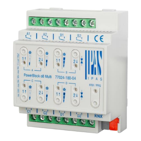
PowerBlock o8 Multi
Order number: 77024-180-04
General usage
Power Block series consists of 4 different devices types. It can be
installed in a standard distribution board.
•only 4 DIN Rail modules for 4 outputs and 6 inputs
•only 4 DIN Rail modules for 8 outputs
(Binary/Shutter/Blind/Fan Coil)
•only 8 DIN Rail modules for 16 outputs
(Binary/Shutter/Blind/Fan Coil)
A brief overview of the functionality is given in the following table:
Device type and accessories
At present the following device types are available in the PowerBlock
control group:
Product
Description
Order number:
PowerBlock o8m
8 capacitive outputs
77024-180-04
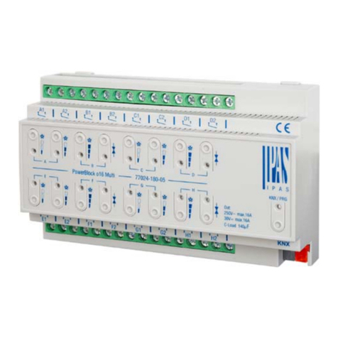
PowerBlock o16m
16 capacitive outputs
77024-180-05
PowerBlock io64
4 capacitive outpus +
6 analog / digital inputs
77024-180-03
InBlock
8 x 230VAC inputs
7704-180-30
Scope of delivery
The following individual components are included in the delivery of the
PowerBlock device:
- Complete device with connected bus connector
- Operating and mounting instructions
- 1x heat shrinkable tubing 1.2 x 2cm for additional insulation
of the bus cable
- Delivered in break-proof individual packaging
Application programs
The following application programs are currently available for the
PowerBlock device:
- 77014-PowerBlock o8m-21-0110
Installation device
Risk of death by electric shock.
•The device is intended for interior installation in dry rooms.
•The device must only be installed and commissioned by an
accredited electrical engineer.
•When planning and construction of electrical installations, the
national guidelines, rules and regolations of the country in quest-
ions are to be obeyed, as well as all current KNX guide lines.
•For the installation the device must be switched to zero potential.
•The device must not be opened.
•Any faulty devices is to be sent together with a return delivery to
the manufacturer.
Technical data
POWER AND OUTPUTS SPECIFICATIONS
Power supply
Via KNX bus
Max. current
consumption
21..30VDC
9,4mA
Additional
supply
No
Number of
outputs
8 Dry contact (potential-free)
Output
configuration
Up to 8 outputs / Up to 4
channels / Up to 2 FAN
COIL controllers
Output nominal
values
AC rated current /
voltage
DC rated current /
voltage
16A / 250VAC 50/60Hz
C-Loads max. = 140 µF
16A / 30VAC
Device nominal
values
Current/Voltage
16A /250VAC per Output
Phases
switching
distribution
1 independent phase
allowed per output
Output life
expectance
Mechanical
Electrical
 operations (at 60
times/min)
 cycles with resistive
load at max current
Connections
KNX bus connection
terminal:
Terminal screw
block:
Tightening torque for
terminal screw:
0,8 mm Ø solid
max. 6 mm Ø solid
maximum 0.6 Nm
GENERAL SPECIFICATIONS
Control and
display
elements
Programming button
LED:
8 x buttons for
manual channels
control:
8 x LEDs
To assign the physical
address
To switch On/Off outputs /
Move Up/Down channels /
Select Fan Speed and to
switch valve output.
To display actual
outputs/channels status
Outputs
BINARY ( POWER LEDs
SUPPORTED)
SHUTTER / BLIND
Bus failure
Bus failure
Central ON/OFF
Counters
Scenes
Timers
Alarms
Disable function
Manual control
Scenes
Presets
Alarms
Disable function
Manual control
Façade control
Shutter slits control
True height positioning for
shutter/blind
ADVANCED FUNCTIONS
FAN COIL (FC)
Analog & digital alarms
Fan Auto/Manual
Scene controler
Timers (with cyclic sending of
time remaining
Overwrite end user parameters
Logic functions
Setpoints
Behavior at bus recovery
Operation modes (Fan & Valve
restrictions)
Manual fan speed with multiple
DPTs obj
Remaining time to change filter
Fan speed timers/delays/cyclic
Scenes and Day & Night object
Purge valve
Thermostat monitoring
Alarms
BMA 77024-o8m-01_Rev2_en IPAS GmbH, Hölscherstraße 27, D-47167 Duisburg [email protected]
Mechanical
data
Dimensions REG
casing 4TE:
Width:
Hight:
Lenght:
Weight
Mounting:
Plastic
72 mm
58 mm
90 mm
235 g
35 mm DIN rail
Electrical safty
Protection type
inaccordance with
EN60529):
KNX Bus:
IP20
Separated extra-low voltage
SELV DC 24
EMC
requirements
Complies with:
Overvoltage
category:
EN 50090-2-2
class III
Environmental
conditions
Clima conditions:
Operation
temperature:
Storage
temperature:
Rel. humidity (non
condensing):
EN 60721-3-3 class 3k5
-5°C to +45°C
-25°C to +70°C
5 % to 93 %
Certification
CE-Signage
KNX registered
According to EMC-
Guidelines (Residential and
commercial buildings), Low
Voltage guidelines
Location and function of the LEDs and control elements
Mounting and wiring
As an REG device, the Power Block series are suitable for mounting in
distribution boxes on 35 mm DIN rails and wall boxes.
To mount the device, it must be angled to slide onto the DIN rail from
above and then locked into place with a downward movement.
Please make sure that the security latch at the bottom side of the
device snaps into place and that the device is firmly attached to the
rail. To dismount the device, the security latch can be pulled
downwards with a suitable tool and then the device can be removed
from the rail.
After the device has been inserted, the cables for the Outputs should
be attached to the upper and lower connectors. However, please make
sure that these are labelled clearly.
The power supply is connected to the bottom right-hand side
connector according to the order indicated on the casing. To connect
the KNX cable, a standard bus connector is plugged into the
respective entry on the device. Please make sure that there is double
basic insulation between the KNX installation and the power supply. To
do so, please insulate the wires of the KNX cable up to the bus
connector with the enclosed shrinkable tubing.
Please make sure that the cables are laid in a way that ensures
sufficient distance between the inputs and outputs cables.
1: KNX bus connector
2: Programming button
3: Programming LED
4: SD card slot (only for internal use)
5: Outputs connector: Channel A, B
LED output/channel status
6.1: Binary channel LED ON = Output ON, LED OFF = Output OFF /
Shutter: LED blinks while moving UP
Fan Coil (Type of Fan = Single):
- LED ON = Fan Speed 1 ON
- LED OFF = Fan Speed 1 OFF
6.2: Binary channel LED ON = Output ON, LED OFF = Output OFF /
Shutter: LED blinks while moving DOWN
Fan Coil (Type of Fan = Single):
- LED ON = Fan Speed 2 ON
- LED OFF = Fan Speed 2 OFF
6.3: Fan Coil (Type of Fan = Single):
- LED ON = Fan Speed 3 ON
- LED OFF = Fan Speed 3 OFF
6.4: Fan Coil (Valve Output):
- LED ON = Valve ON
- LED OFF = Valve OFF
7.1: Manual control (See Annex 1)
Blind channel:
- Long press: Move Up (LED blinks while moving)
- Short press: Stop/Step
Binary channel:
- Short press: Output toggles to ON/OFF
FC Fan Speed:
- Short press: Fan Speed 1 is selected
7.2: Manual control (See Annex 1)
Blind channel:
- Long press: Move Down (LED blinks while moving)
- Short press: Stop/Step
Binary channel:
- Short press: Output toggles to ON/OFF
FC Fan Speed:
- Short press: Fan Speed 2 is selected
7.3: Manual control (See Annex 1)
FC Fan Speed:
- Short press: Fan Speed 3 is selected
7.4: Manual control (See Annex 1)
FC Valve Output:
- Short press: Output valve toggles to ON/OFF
8: Outputs connector: Channel C, D
4
6.1
6.2
2
1
3
7.3
72 mm / 4 DIN RAIL
7.1
7.2
8
7.4
5
6.3
6.4
BMA 77024-o8m-01_Rev2_en IPAS GmbH, Hölscherstraße 27, D-47167 Duisburg [email protected]
OUTPUT SCHEMATIC
Each channel can be configured to be used as 2 binary outputs or as one blind channel. In case Fan Coil controller is selected, 4 outputs will be used.
Each output can be powered by an independent phase.
BMA 77024-o8m-01_Rev2_en IPAS GmbH, Hölscherstraße 27, D-47167 Duisburg [email protected]
ANNEX 1: Manual Control
Attention: This option is activated after ETS Download. In delivery
status this option is not available.
The Power Block actuator has 2 push buttons and 2 status LEDs for
each channel on the front side. These buttons can be activated to
control each and every channel/output individually if you select “yes” in
the relevant parameter options in Binary outputs / Shutter/Blinds / Fan
Coil. The LEDs are arranged in two rows, whereas the LEDs
represent:
For Binary outputs
•The top row: channels A1,A2,B1,B2
•The bottom row: channels C1,C2,D1, D2
For Shutter/blinds:
•The top row: channel's first relay A1->UP,
A2->DOWN, B1-UP, etc.
•The bottom row: channel's seccond relay C1->UP,
C2-> DOWN, D1-> UP, etc.
For Fan Coil:
•The top row:
- FC1: Fan Speed = Fan 1 (A1),
Fan 2 (A2), Fan 3 (B1) // Output valve = B2.
•The bottom row:
- FC2: Fan Speed = Fan 1 (C1),
Fan 2 (C2), Fan 3 (D1) // Output valve = D2.
MANUAL CONTROL –PARAMETER
The Parameter Mode allows you to control all the channels of the
actuator as configured in the ETS. The Action simulates a telegram
received at the switching object of the selected channel.
BINÄRY
SHUTTER/BLIND
Betätigung: Sendet Press
action: Sends Toggle ON/OFF
command “0/1” to the
“Switching” object.
.
LED = ON (indicates
channel status)
LED = OFF (indicates
channel status)
Long press action (Channel
output 1):
Sends a UP command “0” to the
“Move” object.
Long press action (Channel
output 2):
Sends a DOWN command “1” to
the “Move” object.
Short press action (any output)
(while shutter/blind is moving) of
same button:
Sends a Stop command to the
“Stop…” object.
LED blinks while moving
UP/DOWN during parameterized
time.
Fan Coil
Valve press action: Sends toggle ON/OFF command to the relay (ON
= Contact closed / OFF = Contact open)
Fan speed press action: Actives the selected Fan Speed switching the
corresponding relays, depending of the configuration Fan Coil Type
(Single or Multiple)
Type of Fan Coil = Single (Only one output can be ON at time)
oLED = ON (indicates the actual Fan Speed active)
oLED = OFF (indicates the actual Fan Speed is not active)
Type of Fan Coil = Multiple (Switch outputs sequentially ON)
oLED = ON (Accumulated ON status, it indicates the actual
Fan Speed active)
oLED = OFF (indicates the actual Fan Speed is not active)
MANUAL CONTROL –TEST
The Test Mode allows you to test all the loads/wiring connected to the
channels. It is independent from the ETS configuration of the actuator
(since the “Manual Control / Param mode + Test mode” is a default
option, you can use the Test mode even before programming the
actuator).
Important note: Should a blind/shutter be connected to a channel, the
2 channels may never be closed at the same time. Therefore, even in
Test mode, if the channel is configured as a blind, this safety measure
is implemented. For this reason, it is better to first commission the
OUTPUT: CHANNEL TYPE SELECTION before using the Test mode.
To change into the test mode, any button can be used depending of
the channel configuration:
- If “Binary” or ”Fan Coil” channel is configured: Press any button for
at least 500ms
- If “Blind” channel is configured: Press the two buttons of any channel
at the same time for at least 500ms
To change back to the normal “Parameter Mode” the same procedure
should be repeated. Be aware by changing back to “Parameter Mode”
the device will restart. Also after the device has restarted and if the
channel is configured to be a blind channel, it will do a calibration
movement on the first movement command.
In order to indicate that the actuator is in Manual Control / Test
Mode, the LED of the selected channel is continuously making a short
blinking action every second; no matter whether the channel is ON
(LED ON) or OFF (LED OFF).
The Action switches/moves the channel, as you can see in the table
below:
BINÄR
JALOUSIEN/BLENDE
Press action: Sends toggle
ON/OFF command to the relay
(ON = Contact closed / OFF =
Contact open)
LED = ON (indicates
channel status)
LED = OFF (indicates
channel status)
Rising edge press action
(Channel X): Contact closed
Falling edge press action
(Channel X): Contact open
LED = ON (indicates
channel status)
LED = OFF (indicates
channel status)
Fan Coil
Valve press action: Sends toggle ON/OFF command to the relay (ON
= Contact closed / OFF = Contact open)
Fan speed press action: Actives the selected Fan Speed switching the
corresponding relays, depending of the configuration Fan Coil Type
(Single or Multiple)
Type of Fan Coil = Single (Only one output can be ON at time)
oLED = ON (indicates the actual Fan Speed active)
oLED = OFF (indicates the actual Fan Speed is not active)
Type of Fan Coil = Multiple (Switch outputs sequentially ON)
oLED = ON (Accumulated ON status, it indicates the actual
Fan Speed active)
oLED = OFF (indicates the actual Fan Speed is not active)
LED = ON (indicates channel status)
LED = OFF (indicates channel status)

This manual suits for next models

2

Other IPAS Controllers manuals

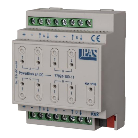
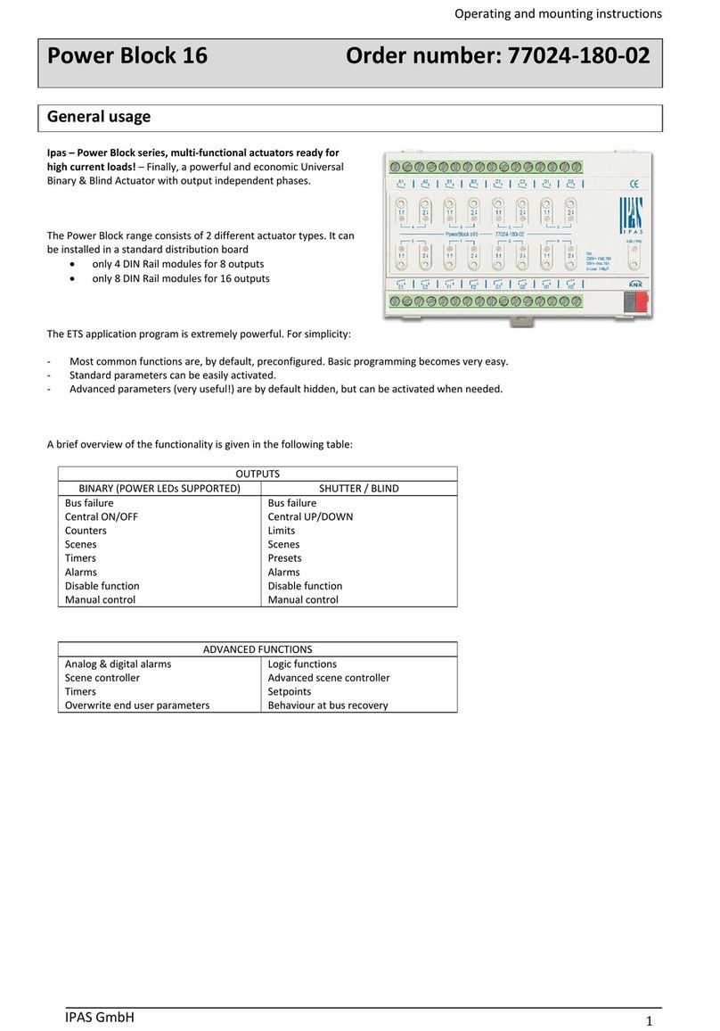
IPAS Power Block Series Service manual

IPAS

IPAS Power Block Series Service manual

IPAS PowerBlock s4 DC Service manual

IPAS

IPAS PowerBlock s4 DC Service manual

IPAS Power Block Series Service manual

IPAS

IPAS Power Block Series Service manual

IPAS PowerBlock o16 Multi Service manual

IPAS

IPAS PowerBlock o16 Multi Service manual

Popular Controllers manuals by other brands

Lawler 802 SEA Deluxe Installation & maintenance manual

Lawler

Lawler 802 SEA Deluxe Installation & maintenance manual

Victron energy SmartSolar MPPT 100/30 manual

Victron energy

Victron energy SmartSolar MPPT 100/30 manual

Siemens CPU 948 Programming guide

Siemens

Siemens CPU 948 Programming guide

Pickering 60-981 user manual

Pickering

Pickering 60-981 user manual

JOVENTA DAF.10 Series installation guide

JOVENTA

JOVENTA DAF.10 Series installation guide

Circutor CDP series Application notes

Circutor

Circutor CDP series Application notes

Azbil Infilex GC WY5111 instructions

Azbil

Azbil Infilex GC WY5111 instructions

Carrier 40VM900006 installation instructions

Carrier

Carrier 40VM900006 installation instructions

Mindman MAER210/310 Series Service manual

Mindman

Mindman MAER210/310 Series Service manual

BFT IGEA LB Installation and user manual

BFT

BFT IGEA LB Installation and user manual

Welbilt Frymaster FilterQuick easyTouch Operation manual

Welbilt

Welbilt Frymaster FilterQuick easyTouch Operation manual

afx light PIXSTRIP-C user manual

afx light

afx light PIXSTRIP-C user manual

eControls e-Room Panasonic Stand-Alone instruction sheet

eControls

eControls e-Room Panasonic Stand-Alone instruction sheet

HANYOUNG NUX TPR-3SL instruction manual

HANYOUNG NUX

HANYOUNG NUX TPR-3SL instruction manual

Süd wind ambientika WallPanel manual

Süd wind

Süd wind ambientika WallPanel manual

Meanwell CMU2C installation manual

Meanwell

Meanwell CMU2C installation manual

Arun Microelectronics LTD NGC2D user manual

Arun Microelectronics LTD

Arun Microelectronics LTD NGC2D user manual

Timeguard TLRX05 Installation & operating instructions

Timeguard

Timeguard TLRX05 Installation & operating instructions

manuals.online logo
manuals.online logoBrands
  • About & Mission
  • Contact us
  • Privacy Policy
  • Terms and Conditions

Copyright 2025 Manuals.Online. All Rights Reserved.