IPAS Power Block Series Service manual

Operatingandmountinginstructions
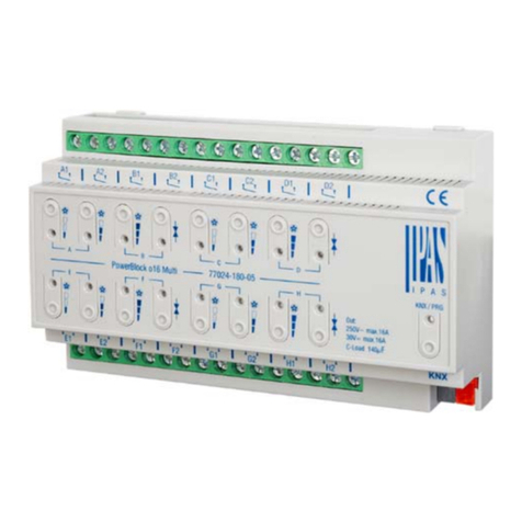
PowerBlock16Ordernumber:77024‐180‐02
IPASGmbH
1
Generalusage
Ipas–PowerBlockseries,multi‐functionalactuatorsreadyfor
highcurrentloads!–Finally,apowerfulandeconomicUniversal
Binary&BlindActuatorwithoutputindependentphases.
ThePowerBlockrangeconsistsof2differentactuatortypes.Itcan
beinstalledinastandarddistributionboard
only4DINRailmodulesfor8outputs
only8DINRailmodulesfor16outputs
TheETSapplicationprogramisextremelypowerful.Forsimplicity:
‐Mostcommonfunctionsare,bydefault,preconfigured.Basicprogrammingbecomesveryeasy.
‐Standardparameterscanbeeasilyactivated.
‐Advancedparameters(veryuseful!)arebydefaulthidden,butcanbeactivatedwhenneeded.
Abriefoverviewofthefunctionalityisgiveninthefollowingtable:
OUTPUTS
BINARY(POWERLEDsSUPPORTED)SHUTTER/BLIND
BusfailureBusfailure
CentralON/OFFCentralUP/DOWN
CountersLimits
ScenesScenes
TimersPresets
AlarmsAlarms
DisablefunctionDisablefunction
ManualcontrolManualcontrol
ADVANCEDFUNCTIONS
Analog&digitalalarmsLogicfunctions
ScenecontrollerAdvancedscenecontroller
TimersSetpoints
OverwriteenduserparametersBehaviouratbusrecovery

Operatingandmountinginstructions
PowerBlock16Ordernumber:77024‐180‐02
IPASGmbH
2
Devicetypeandaccessories
AtpresentthefollowingdevicetypesareavailableinthePowerBlockcontrolgroup
Ref.DescriptionOrdernumber:
PowerBlock88Capacitiveoutputs 77024‐180‐01
PowerBlock1616Capacitiveoutputs 77024‐180‐02
Scopeofdelivery
ThefollowingindividualcomponentsareincludedinthedeliveryofthePowerBlockdevice:
- Completedevicewithconnectedbusconnector
- Operatingandmountinginstructions
- Deliveredinbreak‐proofindividualpackaging
Applicationprograms
ThefollowingapplicationprogramsarecurrentlyavailableforthePowerBlockdevice:
- 77014‐PowerBlocko16‐12‐0110
Forapplicationprogramfunctions,pleaseseetheapplicationprogramdescription.
Installationdevice
- Riskofdeathbyelectricshock
- Thedeviceisintendedforinteriorinstallationindryrooms.
- Thedevicemustonlybeinstalledandcommissionedbyanaccreditedelectricalengineer.
- Pleasefollowcountry‐specificsafetyandaccidentpreventionrulesaswellasallcurrentKNXguidelines.
- Pleasefollowcountry‐specificrulesandregulationsfortheplanningandconstructionofinstallations,especiallywithregardto
emergencylightingsystems.
- Fortheinstallationthedevicemustbeswitchedtozeropotential.
- Donotopenthedevice!Faultydevicesmustbereturnedtothemanufacturer.

Operatingandmountinginstructions
PowerBlock16Ordernumber:77024‐180‐02
IPASGmbH
3
Technicaldata
POWER&OUTPUTSSPECIFICATIONS
Powersupply
ViaKNXbus
Max.currentconsumption
21..30VDC
10mA
AdditionalsupplyNo
Numberofoutputs16Drycontact(potential‐free)
OutputconfigurationUpto16outputs/Upto8channels
Outputnominalvalues
ACratedcurrent/voltage
DCratedcurrent/voltage
16A/250VAC50/60Hz
C‐Loadsmax.=140µF
16A/30VDC
DevicenominalvaluesCurrent/Voltage16A/250VACperOutput
Max.loadratingperdevice16out.x16A=256A/250VAC50/60Hz
Phasesswitchingdistribution1independentphaseallowedperoutput
OutputlifeexpectanceMechanical
Electrical
310
operations(at60times/min)
410
cycleswithresistiveloadatmax
current
ConnectionsKNXbusconnectionterminal
Terminalscrewblock
Tighteningtorqueforterminalscrew
0,8mm²solid
max.6mm²Øsolid
maximum0.5Nm
GENERALSPECIFICATIONS
Controlanddisplay
elements
ProgrammingbuttonLED
16xbuttonsformanualchannelscontrol
16xLEDs
Toassignthephysicaladdress
ToswitchOn/Offoutputsandmove
Up/Downchannels.
Todisplayactualoutputs/channelsstatus
Mechanicaldata
Casing:
DimensionsREGcasing4TE(Width/Height/Length)
Weight:
Mounting:
PlasticABS–V0
60mm/90mm/144mm
440gr
35mmDINrail
Electricalsafety
Degreeofcontamination:
Protectiontype(inaccordancewithEN60529):
Protectionclass(accordingtoIEC1140):
Overvoltagecategory:
KNXBus:
2
IP20
classII
classIII
Separatedextra‐lowvoltageSELVDC24
EMCrequirementsComplieswith:EN50491‐5‐2/EN50491‐5‐3
Environmentalconditions
Climaconditions:
Operationtemperature:
Storagetemperature:
Rel.humidity(noncondensing):
EN60721‐3‐3class3k5
‐5°Cto+45°C
‐25°Cto+70°C
5%to93%
Certification
CE‐Signage
KNXregistered
AccordingtoEMC‐Guidelines(Residential
andcommercialbuildings),LowVoltage
guidelines

Operatingandmountinginstructions
PowerBlock16Ordernumber:77024‐180‐02
IPASGmbH
4
LocationandfunctionoftheLEDsandcontrolelements
TheprogrammingbuttonandprogrammingLEDarerequiredforcommissioningandareonlyaccessibleinthedistributionbox
whenthecoverisremoved.
1:KNXbusconnector7.1:Manualcontrol(SeeAnnex1)
2:Programmingbutton
3:ProgrammingLED
4:SDcardslot(onlyforinternaluse)
5:Outputsconnector:ChannelA,B,C,D
Blindchannel:
‐Longpress:MoveUp(LEDblinkswhilemoving)
‐Shortpress:Stop/Step
Binarychannel:
‐Shortpress:OutputtogglestoON/OFF
LEDoutput/channelstatus
6.1:BinarychannelLEDON=OutputON,LEDOFF=Output
OFF/Shutter:LEDblinkswhilemovingUP
6.2:BinarychannelLEDON=OutputON,LEDOFF=Output
OFF/Shutter:LEDblinkswhilemovingDOWN
7.2:Manualcontrol(SeeAnnex1)
Blindchannel:
‐Longpress:MoveDown(LEDblinkswhilemoving)
‐Shortpress:Stop/Step
Binarychannel:
‐Shortpress:OutputtogglestoON/OFF
8:Outputsconnector:ChannelE,F,G,H
5
2
1
4
6.2
3
8
144mm/8DIN
6.1
7.1
7.2

Operatingandmountinginstructions
PowerBlock16Ordernumber:77024‐180‐02
IPASGmbH
5
Mountingandwiring
AsanREGdevice,thePowerBlockseriesaresuitableformountingindistributionboxeson35mmDINrailsandwallboxes.To
mountthedevice,itmustbeangledtoslideontotheDINrailfromaboveandthenlockedintoplacewithadownward
movement.
Pleasemakesurethatthesecuritylatchatthebottomsideofthedevicesnapsintoplaceandthatthedeviceisfirmlyattachedto
therail.Todismountthedevice,thesecuritylatchcanbepulleddownwardswithasuitabletoolandthenthedevicecanbe
removedfromtherail.
Afterthedevicehasbeeninserted,thecablesfortheOutputsshouldbeattachedtotheupperandlowerconnectors.However,
pleasemakesurethatthesearelabelled clearly.
Thepowersupplyisconnectedtothebottomright‐handsideconnectoraccordingtotheorderindicatedonthecasing.To
connecttheKNXcable,astandardbusconnectorispluggedintotherespectiveentryonthedevice.Pleasemakesurethatthere
isdoublebasicinsulationbetweentheKNXinstallationandthepowersupply.Todoso,pleaseinsulatethewiresoftheKNXcable
uptothebusconnectorwiththeenclosedshrinkabletubing.
Pleasemakesurethatthecablesarelaidinawaythatensuressufficientdistancebetweentheinputsandoutputscables
OUTPUTSSCHEMATIC
Eachchannelcanbeconfiguredtobeusedas2binaryoutputsorasoneblindchannel.Eachoutputcanbepoweredbyan
independentphase.

Operatingandmountinginstructions
PowerBlock16Ordernumber:77024‐180‐02
IPASGmbH
6
ANNEX1:MANUALCONTROL
ThePowerBlockactuatorhas2pushbuttonsand2statusLEDsforeachchannelonthefrontside:
‐Thesebuttonscanbeactivatedtocontroleachandeverychannel/outputindividuallyifyouselect“yes”intherelevant
parameteroptionsinBinaryoutputsand/orShutter/Blinds.
‐TheLEDsarearrangedintworows,whereastheLEDsrepresent:
oForBinaryoutputs:
Thetoprow:channelsA1,A2,B1,B2,C1,C2,D1,D2
Thebottomrow:channelsE1,E2,F1,F2,G1,G2,H1,H2.
oForShutter/blinds:
Thetoprow:channel’sfirstrelayA1‐>UP,A2‐>DOWN,B1‐UP,etc.
Thebottomrow:channel’ssecondrelayE1‐>UP,E2‐>DOWN,F1‐>UP,etc.
MANUALCONTROL–PARAMETERMODE
TheParameterModeallowsyoutocontrolallthechannelsoftheactuatorasconfiguredintheETS.
TheActionsimulatesatelegramreceivedattheswitchingobjectoftheselectedchannel.
BINARY
SHUTTER/BLIND
Pressaction:SendsToggleON/OFFcommand“0/1”tothe
“Switching”object
LED=ON(indicateschannelstatus)
LED=OFF(indicateschannelstatus)
‐Longpressaction(Channeloutput1):SendsaUPcommand
“0”tothe“Move”object.
‐Longpressaction(Channeloutput2):SendsaDOWN
command“1”tothe“Move”object.
‐Shortpressaction(anyoutput)(whileshutter/blindis
moving)ofsamebutton:sendsaStopcommandtothe
“Stop…”object.
LEDblinkswhilemovingUP/DOWNduring
parameterizedtime

Operatingandmountinginstructions
PowerBlock16Ordernumber:77024‐180‐02
IPASGmbH
7
MANUALCONTROL–TESTMODE
TheTestModeallowsyoutotestalltheloads/wiringconnectedtothechannels.ItisindependentfromtheETSconfiguration
oftheactuator(sincethe“ManualControl/Parammode+Testmode”isadefaultoption,youcanusetheTestmodeeven
beforeprogrammingtheactuator).
Importantnote:Shouldablind/shutterbeconnectedtoachannel,the2channelsmayneverbeclosedatthesametime.
Therefore,eveninTestmode,ifthechannelisconfiguredasablind,thissafetymeasureisimplemented.Forthisreason,itis
bettertofirstcommissiontheOUTPUT:CHANNELTYPESELECTIONbeforeusingtheTestmode.
Tochangeintothetestmode,anybuttoncanbeuseddependingofthechannelconfiguration:
‐If“Binary”channelisconfigured:Pressanybuttonforatleast500ms
‐If“Blind”channelisconfigured:Pressthetwobuttonsofanychannelatthesametimeforatleast500ms
Tochangebacktothenormal“ParameterMode”thesameprocedureshouldberepeated.Beawarebychangingbackto
“ParameterMode”thedevicewillrestart.Alsoafterthedevicehasrestartedandifthechannelisconfiguredtobeablind
channel,itwilldoacalibrationmovementonthefirstmovementcommand.
InordertoindicatethattheactuatorisinManualControl/TestMode,theLEDoftheselectedchanneliscontinuously
makingashortblinkingactioneverysecond;nomatterwhetherthechannelisON(LEDON)orOFF(LEDOFF).
TheActionswitches/movesthechannel,asyoucanseeinthetablebelow:
BINARY
SHUTTER/BLIND
‐Pressaction:SendstoggleON/OFFcommandtothe
relay(ON=Contactclosed/OFF=Contactopen)
LED=ON(indicateschannelstatus)
LED=OFF(indicateschannelstatus)
‐Risingedgepressaction(ChannelX):Contactclosed
‐Fallingedgepressaction(ChannelX):Contactopen
LED=ON(indicateschannelstatus)
LED=OFF(indicateschannelstatus)
This manual suits for next models
3
Table of contents
Other IPAS Controllers manuals