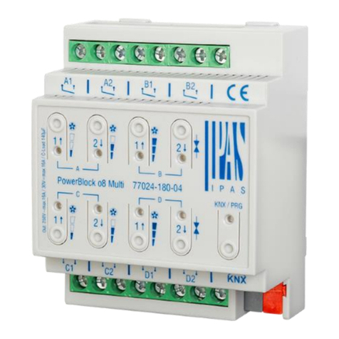
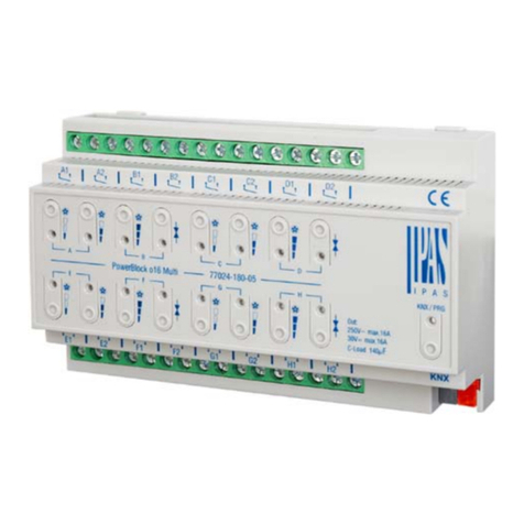
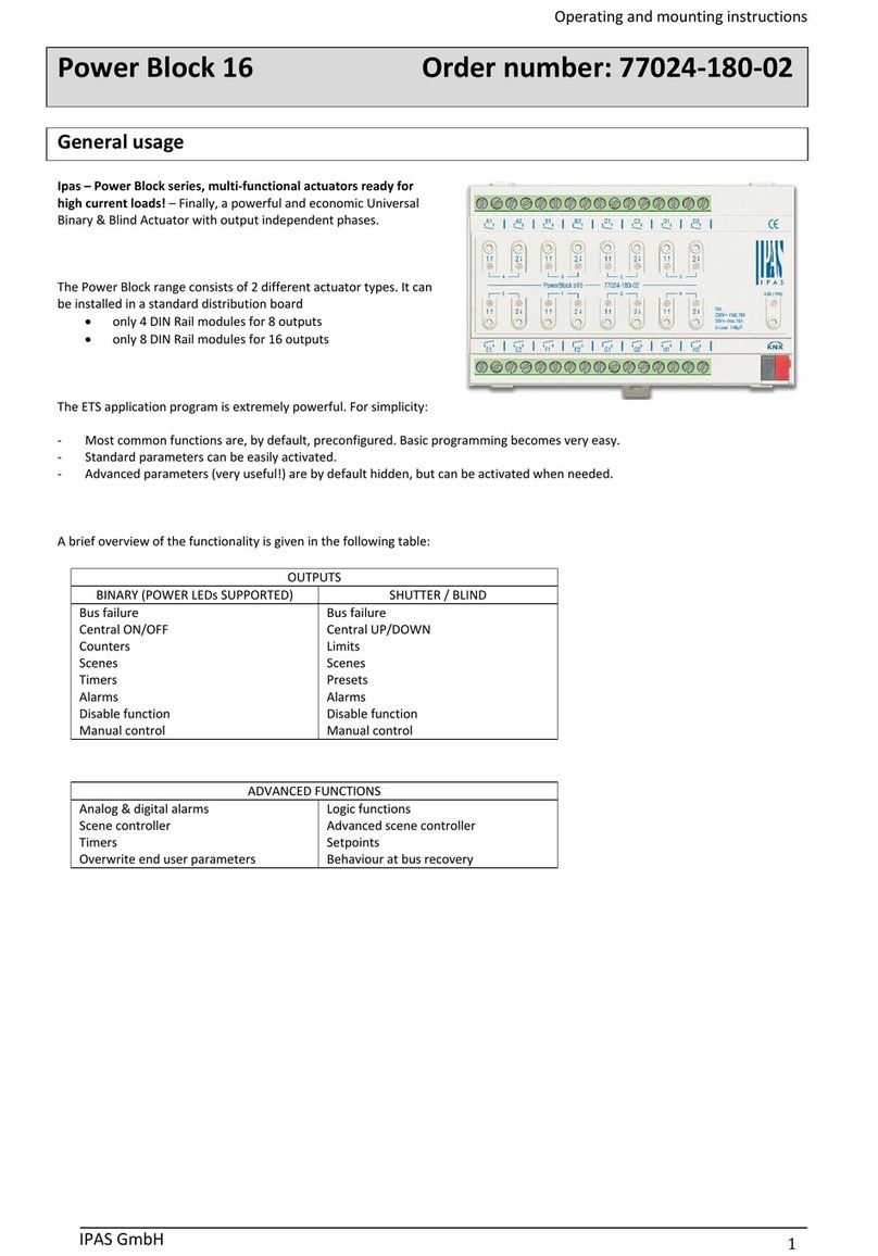
Location and function of the LEDs and control elements
Mounting and wiring
As an REG device, the Power Block series are suitable for mounting in
distribution boxes on 35 mm DIN rails and wall boxes.
To mount the device, it must be angled to slide onto the DIN rail from
above and then locked into place with a downward movement.
Please make sure that the security latch at the bottom side of the
device snaps into place and that the device is firmly attached to the
rail. To dismount the device, the security latch can be pulled
downwards with a suitable tool and then the device can be removed
from the rail.
After the device has been inserted, the cables for the Outputs should
be attached to the upper and lower connectors. However, please make
sure that these are labelled clearly.
To connect the KNX cable, a standard bus connector is plugged into
the respective entry on the device. Please make sure that there is
double basic insulation between the KNX installation and the power
supply. To do so, please insulate the wires of the KNX cable up to the
bus connector with the enclosed shrinkable tubing.
Please make sure that the cables are laid in a way that ensures
sufficient distance between the inputs and outputs cables.
OUTPUTS SCHEMATIC
Each channel can be configured to be used as one shutter channel
for DC motor:
ANNEX 1: Manual Control
The Power Block actuator has 2 push buttons and 2 status
LEDs for each channel on the front side:
These buttons can be activated to control each and every
channel individually if you select “yes” in the relevant
parameter options in Shutter/Blinds. The LEDs are arranged in
two rows, whereas the LEDs represent:
- The top row: A ->UP, A->DOWN, B->UP, B->DOWN
- The bottom row: C->UP, C-> DOWN, D-> UP, B->DOWN
MANUAL CONTROL PARAMETER
The Parameter Mode allows you to control all the channels of
the actuator as configured in the ETS. The Action simulates a
telegram received at the switching object of the selected
channel.
Long press action:
Sends a UP command “0” to the “Move” object.
Long press action (Channel output 2):
Sends a DOWN command “1” to the “Move” object.
Short press action (while shutter/blind is moving) of same
button:
Sends a Stop command to the “Stop…” object
LED blinks while moving UP/DOWN during
parameterized time
LED channel status
- Shutter: LED blinks while moving UP
- Shutter: LED blinks while moving DOWN


