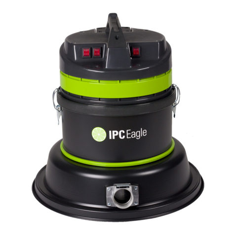
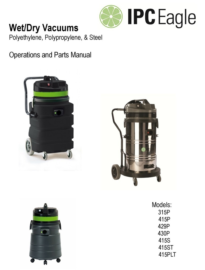
IPC Eagle 415P-AD Guide

Pump Out Vacuums
Polyethylene & Steel
Operations and Parts Manual
Models:
415P-AD
429P-AD
415DS

2
IMPORTANT SAFETY INSTRUCTIONS
IMPORTANT SAFETY INSTRUCTIONSIMPORTANT SAFETY INSTRUCTIONS
IMPORTANT SAFETY INSTRUCTIONS
When using an electrical appliance, basic precauti n must always be f ll wed, including the f ll wing:
READ ALL INSTRUCTIONS BEFORE USING THIS MACHINE.
READ ALL INSTRUCTIONS BEFORE USING THIS MACHINE.READ ALL INSTRUCTIONS BEFORE USING THIS MACHINE.
READ ALL INSTRUCTIONS BEFORE USING THIS MACHINE.
This machine is f r c mmercial use.
WARNING
WARNINGWARNING
WARNING
DANGER:
DANGER: DANGER:
DANGER:
Failure t read and bserve all DANGER statements c uld result in severe b dily injury
r death. Read and bserve all DANGER statements f und in y ur Owner’s Manual and n y ur
machine.
WARNING:
WARNING: WARNING:
WARNING:
Failure t read and bserve all WARNING statements c uld result in injury t y u r t
ther pers nnel; pr perty damage c uld ccur as well. Read and bserve all WARNING statements
f und in y ur Owner’s Manual and n y ur machine.
CAUTION:
CAUTION: CAUTION:
CAUTION:
Failure t read and bserve all CAUTION statements c uld result in damage t the
machine r t ther pr perty. Read and bserve all CAUTION statements f und in y ur Owner’s
Manual and y ur machine.
DANGER:
DANGER: DANGER:
DANGER:
Failure t read the Owner’s Manual pri r t perating r attempting any service r
maintenance pr cedure t y ur machine c uld result in injury t y u r t ther pers nnel; damage t
the machine r t ther pr perty c uld result as well. Y u must have training in the perati n f this
machine bef re using it. If y u r y ur perat r(s) cann t read English, have this manual explained
fully bef re attempting t perate this machine.
DANGER:
DANGER: DANGER:
DANGER:
Operating a machine that is n t c mpletely r fully assembled c uld result in injury r
pr perty damage. D n t perate this machine until it is c mpletely assembled. Inspect the machine
carefully bef re perati n. Use nly as described in this manual. Use nly the manufacturer’s
rec mmended attachments.
DANGER:
DANGER: DANGER:
DANGER:
Machines can cause an expl si n when perated near flammable materials and vap rs.
D n t use this machine with r near fuels, grain dust, s lvents, thinners, r ther flammable
materials.
DANGER:
DANGER: DANGER:
DANGER:
D n t
D n t D n t
D n t pick up flammable fluids, dust r vap rs.
DANGER:
DANGER: DANGER:
DANGER:
D n t
D n t D n t
D n t vacuum anything that is burning r sm king, such as cigarettes, matches, r h t
ashes.
DANGER:
DANGER: DANGER:
DANGER:
This machine is n t
is n t is n t
is n t suitable f r picking up health endangering dust.
DANGER:
DANGER: DANGER:
DANGER:
Using a machine with a damaged p wer c rd c uld result in an electr cuti n. D n t use
the machine if the p wer c rd is damaged. D n t use the electrical c rd t m ve the machine. Keep
c rd away fr m heated surfaces. D n t unplug by pulling n the c rd; grasp the plug, n t the c rd.
Turn ff all c ntr ls bef re unplugging. D n t cl se a d r n c rd r pull ar und sharp edges r
c rners.
DANGER:
DANGER: DANGER:
DANGER:
Electr cuti n c uld ccur if maintenance and repairs are perf rmed n a unit that is n t
pr perly disc nnected fr m the p wer s urce. Disc nnect the p wer supply bef re attempting any
maintenance r service.
3
Warning:
Warning: Warning:
Warning:
Operating a machine with ut bserving all labels, decals, etc., c uld result in injury r
damage. Read all machine labels bef re attempting t perate the machine. Make sure all f the
labels are attached r fastened t the machine. Get replacement labels and decals fr m the
manufacturer’s distribut r.
Warning:
Warning: Warning:
Warning:
Electrical c mp nents can “sh rt- ut” if exp sed t water r m isture. Keep the electrical
c mp nents f the machine dry. Always st re the machine in a dry area.
Warning:
Warning: Warning:
Warning:
Use f this machine t m ve ther bjects r t climb n c uld result in injury t the pera-
t r r damage t the machine. D n t use this machine as a step r furniture. D n t all w t be used
as a t y. Cl se attenti n is necessary when used by r near children.
Warning:
Warning: Warning:
Warning:
M ving parts f this machine can cause injury and/ r damage. Keep hands, feet, l se
cl thing, hair, fingers, and all parts f the b dy away fr m penings and m ving parts.
Warning:
Warning: Warning:
Warning:
Electr cuti n c uld ccur if y u handle the plug r appliance with wet hands. D n t handle
plug r appliance with wet hands.
Warning:
Warning: Warning:
Warning:
D n t use with ut dust bag and r filters in place.
Warning:
Warning: Warning:
Warning:
R tating fan blades inside the c ver. Bef re pening c ver, switch ff machine. Wait until
the fan/brush st ps c mpletely r dust and debris may be ejected.
Warning:
Warning: Warning:
Warning:
If the machine is n t w rking pr perly, has been dr pped, damaged, left utd rs, r
dr pped int water, return it t an Auth rized service center.
Warning:
Warning: Warning:
Warning:
Damage c uld ccur t machine if penings are bl cked. D n t put any bject int
penings. D n t use any pening bl cked: keep free f dust, lint, hair, and anything that may reduce
air fl w.
Warning:
Warning: Warning:
Warning:
Injury c uld ccur t the perat r r the machine if used with ut the dust bag and/ r filters
in place. D n t use the machine with ut the dust bag and/ r filters in place.
Warning:
Warning: Warning:
Warning:
Injury t the perat r and/ r damage t the machine c uld ccur when cleaning n stairs,
unless cauti n is used. Use extreme cauti n when cleaning n stairs.
Warning:
Warning: Warning:
Warning:
T reduce the risk f electrical sh ck, always use a 3-wire electrical system c nnected t
the electrical gr und. Whenever p ssible c nnect the machine t an utlet pr tected by a gr und fault
interrupter (GFCI). See “Gr unding Instructi ns.”
SAVE THESE INSTRUCTIONS
SAVE THESE INSTRUCTIONSSAVE THESE INSTRUCTIONS
SAVE THESE INSTRUCTIONS

4
120 V lt Machine Instructi ns F r
120 V lt Machine Instructi ns F r 120 V lt Machine Instructi ns F r
120 V lt Machine Instructi ns F r
C nnecti n T The P wer Supply And The
C nnecti n T The P wer Supply And The C nnecti n T The P wer Supply And The
C nnecti n T The P wer Supply And The
Electrical Gr und
Electrical Gr undElectrical Gr und
Electrical Gr und
This machine must be c nnected t the electrical gr und
t pr tect the perat r fr m electrical sh ck. The machine
has an appr ved p wer c rd with three c nduct rs and a
plug with three terminals. C nnect the plug t a recepta-
cle that has three h les and is c nnected t the electrical
gr und. The green ( r green and yell w) c nduct r in the
c rd is the gr und wire. Never c nnect this wire t any
terminal ther than the gr und terminal.
This machine uses a 120 v lt AC 60 cycle electrical
circuit. Make sure y u have the c rrect frequency and
v ltage bef re c nnecting the p wer c rd t an utlet.
The machine has a plug as sh wn in Figure 1. If a recep-
tacle c nnected t the electrical gr und as sh wn in Fig-
ure 1 is n t available, have ne installed by an electrical
c ntract r. D n t use an adapter.
D n t use an adapter.D n t use an adapter.
D n t use an adapter.
Warning:
Warning: Warning:
Warning:
T reduce the risk f electrical sh ck, pr tect the machine fr m rain. Keep the machine in
a dry area.
Warning:
Warning: Warning:
Warning:
T reduce the risk f electrical sh ck, always use a 3-wire electrical system c nnected t
the electrical gr und. Whenever p ssible c nnect the machine t an utlet pr tected by a gr und fault
interrupter (GFCI).
Warning:
Warning: Warning:
Warning:
D n t cut, rem ve r break the gr und pin. If the utlet d es n t fit the plug, c nsult y ur
electrical c ntract r.
Warning:
Warning: Warning:
Warning:
Have w rn, cut r damaged c rds and plugs replaced by an auth rized service pers n.
Warning:
Warning: Warning:
Warning:
If it bec mes necessary t use an extensi n c rd t reach an electrical utlet, y u must
use ne that is at least ne size larger in wire size. Such as a p wer c rd that is marked 12/3 w uld
need t use an extensi n c rd that is marked 10/3. D n t use an extensi n c rd that is undersized.

5
IMPORTANT INSTRUCTIONS
IMPORTANT INSTRUCTIONSIMPORTANT INSTRUCTIONS
IMPORTANT INSTRUCTIONS
•
Bef re use, the equipment must be c rrectly assembled with all f its c mp nents
•
Check that the electrical utlet is c rrect f r use with the plug n the machine
•
Bef re c nnecting, check that the specified m t r v ltage c rresp nds t the main
v ltage available
•
Never use the equipment near flammable, expl sive r t xic substances: sparks fr m
the m t r c uld cause danger us reacti ns.
•
Always unplug the machine fr m the electrical utlet when leaving machine unattend-
ed r bef re attempting any repair.
•
Service and repair sh uld be d ne by qualified pers nnel nly. Use nly riginal
manufacturer’s replacement parts.
Operati n
Operati nOperati n
Operati n
This machine is a c mmercial vacuum designed f r wet pick up. And must be st red in a
This machine is a c mmercial vacuum designed f r wet pick up. And must be st red in a This machine is a c mmercial vacuum designed f r wet pick up. And must be st red in a
This machine is a c mmercial vacuum designed f r wet pick up. And must be st red in a
dry l cati n.
dry l cati n.dry l cati n.
dry l cati n.
•
Machines with dual vacuum m t rs can be run t gether r independently as the j b
requires.
•
This machine is equipped with a sump pump that has it’s wn independent switch.
When the water level rises, the pump will turn itself n and pump the water ut
thr ugh a c nnected discharge h se.
•
The machine is als equipped with a shut- ff fl at. As the tank is filled t capacity, a
fl at rises and seals the vac intake, causing a l ss f vacuum. Switch ff the vacuum
when this happens and bring the machine t a drain.
•
T empty the machine, make sure the p wer c rd f r the sump pump is plugged int
the A.C. receptacle n the vacuum p wer head r int a separate wall utlet.
After Use
After UseAfter Use
After Use
1
.
St re the c rd n the h k.
2. St re the appliance ind rs, away fr m s urces f heat.
3. This appliance is pr vided with an aut matically reset
thermal limiter t av id damage t m t r. If thermal limiter
perates d ne r m re f the f ll wing:
• Change the bag
• Clean r replace the cartridge filter
• Check h se and tank inlet f r any bstructi ns
• Wait a few minutes f r the thermal limiter t re-cl se the circuit

6
Peri dic Maintenance
Peri dic MaintenancePeri dic Maintenance
Peri dic Maintenance
(Every six t twelve m nths)
(Every six t twelve m nths)(Every six t twelve m nths)
(Every six t twelve m nths)
1. Check filter f r wear, replace dirt saturated filters that d
n t resp nd t n rmal cleaning.
2. Inspect gasket seals and replace th se which have begun t
leak.
3. Examine carb n m t r brushes and c mmutat r.
Servicing The Filter
Servicing The FilterServicing The Filter
Servicing The Filter
Note: This machine does not come standard with filters, they can be added as necessary
The filter is accessed by lifting the head assembly ff the tank.
The P lyester filter assembly is easily rem ved by simply lifting the filter basket ut f the tank.
The cartridge filters they are rem ved very easily. First rem ve the filter retainer by turning the black kn b 90
degrees c unter-cl ckwise. The cartridge filter will then slide ff f the supp rt assembly.
N te:
N te:N te:
N te:
• Be sure t frequently clean the filters.
• All w filters t th r ughly air dry after washing them bef re returning them t the machine.
• W rn filters can affect vacuum perf rmance. Replace the filters when they bec me w rn ut and n rmal
cleaning will n t rest re vacuum perf rmance.
Servicing The Vac M t r
Servicing The Vac M t rServicing The Vac M t r
Servicing The Vac M t r
M t r Replacement
M t r ReplacementM t r Replacement
M t r Replacement
1. Disc nnect p wer c rd fr m p wer s urce.
2. T access the vacuum m t r, rem ve the screws that attach the main c ver t the head assembly and
set the c ver t ne side.
3. Disc nnect the m t r’s 2 red lead wires fr m the main wiring bridge.
4. Disc nnect green/yell w wire by rem ving the screw fr m the m t r c re.
5. Rem ve the f ur m t r m unting screws.
6. Rem ve m t r plate and set aside.
7. Take ut the m t r and rem ve the upper and l wer gaskets.
8. Inspect gaskets. If they sh w signs f wear replace the.
9. Install gaskets nt new m t r ensuring that they are pr perly seated.
10. Install the new m t r. Make sure f am mufflers are p siti ned pr perly.
11. Attach m t r plate t m t r.
12. C nnect green/yell w wire t m t r c re.
13. C nnect m t r’s 2 red lead wires t main wiring bridge.
14. Re-assemble vacuum c ver.
15. Test f r pr per perati n.
S8053200

7
Servicing The Vac M t r
Servicing The Vac M t rServicing The Vac M t r
Servicing The Vac M t r
Carb n Brush Replacement
Carb n Brush ReplacementCarb n Brush Replacement
Carb n Brush Replacement
(Replacement Carb n Brushes: Part# S8053200)
1. Disc nnect p wer c rd fr m p wer s urce.
2. T access the vac m t r, rem ve the screws that attach the main c ver t the head
assembly and set the c ver t ne side.
3. Rem ve the screws that attach the inner c ver t the head assembly and set aside.
4. Rem ve the carb n brush assembly by rem ving the 2 screws that attach it t the vac
m t r. See Figure 1
5. Slide ff the carb n brush c nnect r fr m the m t r terminal. See Figure 2
6. Inspect armature c mmutat r. If it is extremely pitted, gr ved r n t c ncentric then
the m t r will need t be replaced r sent t a qualified service center.
7. Reverse steps 6 thr ugh 4 t install new carb n brush and h using.
8. Repeat steps 4 thr ugh 7 f r the ther carb n brush.
9. Reverse steps 3 and 2 f r re-assembly.
10. Test f r pr per perati n.
Figure 1 Figure 2

8
No. Part # Description Qty.
1 S81122 Power ord 16x3 1
2 S80138 Strain Relief 1
3 S80139 lamp, ord 1
4 S81006 Screw, 5x20 2
5 S82931AUG6 ord Hook 1
6 S81054 Screw 5x30 4
7 S82930G6 Handle 1
8 S81026 Screw 5x25 1
9 S81006 Screw 5x20 2
10 S81005 Screw 5x14 2
11 S83436 Terminal Block 1
12 S81054 Screw 5x30 4
13 S82932AUG6 over, Single Motor 1
14 S81006 Screw 5x20 2
15 S80484 Switch 1
16 S83937 Filter 1
17 S83273 Screw 5x35 9
18 S81502 Grommet 1
19 S83383AU ap 2
20 S82957AUVEI over, Motor 1
21 S82627 Screw 5x25 9
22 S82627 Screw 5x25 3
23 S82937AUG6 Motor Retainer 1
24 S81004 Screw 4.5x20 1
25 S83433 Terminal Board 1
26 S83969 Gasket 1
27 S81979 Screw 5x25 4
29 S83901 Gasket 1
30 S81064 Lock Washer 4x8 1
31 S81024 Screw 4x8 1
32 S81120S Motor 1000 watt 120V 1
33 S83901 Gasket 2
34 S81979 Screw 5x25 8
35 S83901 Gasket 2
36 S83451AU Plug 2
37 S83454 Filter, Sound Deadening 3
38 S83456 Filter 3
39 S83519 ap 2
40 S83108G6 Base w/Gasket 1
41 S81854 Nut, M4 4
42 S86377 Screw, 4x12 4
43 S86457 A Receptacle 110V 1
44 S83453 Gasket, Receptacle 1
415 Vacuum Motor Assembly
Float Assembly 415
No. Part # Description Qty.
1 S83706 Bushing 4
2 S83724 Screw 5x25 4
3 S821243NE Body Filter Assembly 1
4 S82676-1G Float w/Gasket 1

9
No. Part # Description Qty.
1 T82102005 Power ord 14x3 1
2 S80138 Strain Relief 1
3 S80139 lamp, ord 1
4 S81006 Screw, 5x20 2
5 S82931AUG6 ord Hook 1
6 S81054 Screw 5x30 4
7 S82930G6 Handle 1
8 S81026 Screw 5x25 1
9 S81006 Screw 5x20 2
10 S81005 Screw 5x14 2
11 S83436 Terminal Block 1
12 S81054 Screw 5x30 4
13 S82963AUG6 over, Dual Motor 1
14 S81006 Screw 5x20 2
15 S80484 Switch 2
16 S83937 Filter 2
17 S83273 Screw 5x35 9
18 S81502 Grommet 1
19 S83383AU ap 1
20 S82957AUVEI over, Motor 1
21 S82627 Screw 5x25 9
22 S82627 Screw 5x25 3
23 S82937AUG6 Motor Retainer 1
24 S81004 Screw 4.5x20 1
25 S83433 Terminal Board 1
26 S83969 Gasket 2
27 S81979 Screw 5x25 8
29 S83901 Gasket 2
30 S81064 Lock Washer 4x8 2
31 S81024 Screw 4x8 2
32 S81120S Motor 1000 watt 120V 2
33 S83901 Gasket 1
34 S81979 Screw 5x25 4
35 S83901 Gasket 1
36 S83451AU Plug 1
37 S83454 Filter, Sound Deadening 3
38 S83456 Filter 3
39 S83519 ap 1
40 S83108G6 Base w/Gasket 1
41 S81854 Nut, M4 4
42 S86377 Screw, 4x12 4
43 S86457 A Receptacle 110V 1
44 S83453 Gasket, Receptacle 1
42 Vacuum Motor Assembly
Float Assembly 415
No. Part # Description Qty.
1 S83706 Bushing 4
2 S83724 Screw 5x25 4
3 S821243NE Body Filter Assembly 1
4 S82676-1G Float w/Gasket 1

10
Tank and Cart Assembly 415P-AD, 42 P-AD
No. Part# Description Qty.
1 S82558-1 V Handle 1
2 S82623NE Tank, Poly 24g Black 1
3 S81026 Screw 5x30 4
4 S82584G6 Retainer, Tank 1
5 S82846 Gasket 1
6 S82593 Deflector 1
7 S82652AG6VE Inlet over w/button 1
8 S81300 Rivet 4
9 S87390 Latch 2
10
11 S81050 Screw, 5x35 8
12 S82974 Washer, Plastic 4
13 S81072-1NE Support, Handle Front 2
14 S81860-1NE Support, Handle rear 2
15 S81302NE Rivet 4.8x17 2
16 S82559 aster, Swivel 2
17 S82680 Screw 4x15 8
No. Part# Description Qty.
18 S82556 Support, Axle 2
19 S80904 Wheel 2
20 S82557 Retainer, Wheel 2
21 S82607 Spacer, wheel 2
22 S81006 Screw 8
23 S82555 Axle 1
24 S86250 Handle Grip 2
25 S83835NE ap, Wheel 2

11
Tank Assembly 415DS
No. Part# Description Qty.
1 S82993 Handle 2
2 S81847 lamp, Tank 2
3 S81302 Rivet 5x19 4
4 S83629 Screw 5x25 4
5 S83883 Washer 4
6 S81559 Tank 1
7 S81026 Screw 5x30 4
8 S82586 Adapter, Tank 1
9 S82846 Gasket 1
10 S82593 Deflector 1
11 S82583 Inlet over 1
12 S82594 Button 1
13 S82608 Spring 1

12
Cart Assembly 415DS
No. Part# Description Qty.
1 S82993 Handle 1
2 S80917 Support, Handle 2
3 S80913 T-Tube 2
4 S81301 Rivet 5x11 2
5 S80902 Block 1
6 S80914 Hand Wheel 8x60 1
7 S81402 Spring 1
8 S81403 Plate, Threaded 1
9 S81301 Rivet 5x11 2
10 S80901 Base, art 1
11 S80915 Screw 12x140 2
12 S81028 Masher M12 2
13 S80904 Wheel 2
14 S81401 Bushing 2
15 S82052 Spacer 2
16 S81301 Rivet 5x11 2
17 S80479 aster 2
18 S81012 Washer 2
19 S80478 Nut M10 2
20 S86250 Hand Grip 2

13
Pump Assembly
No. Part# Description Qty.
1 DP92372 Pump 1
2 DP99509 heck Valve 1
3 DP99569 Hose Barb 1
4 DP99182 Hose lamp 2
5 DP99190 Hose 1
6 DP99566 Barb, Elbow 11/4” 1
7 DP99565 Bulkhead Fitting 1” 1
8 DP99567 am Lock, Male 1” 1
9 DP99568 am Lock, Female 1” 1
10 DP20310 1” MPT x GHT Fitting 1
11 DPGROM11-2-10 ord Grommet (Not Pictured) 1
1
2
3
4
5
4
6
7
8
9
10

14
Tools
Item Part# Description Qty
S72672 omplete Tool Kit 1
1 S70003 revice Tool 1
2 S76295 Round Brush 1
3 S70008 Hose 1
4 S76387 Wand, Straight 2
5 S76389 Wand, urved 1
6 S76384 16” Floor Brush 1
7 S76385 16” Floor Squeegee 1
7a S82333 Replacement Squeegee Blades 2
1 S76388 Adapter 1
1
2
3
4
5
6
7
8

15
Filters
Part# Description Where Used
S82845 Filter Bag, Standard Polyester 415/429/430 models
S82852* artridge Filter, Paper 415/429/430 models
S76061* artridge Filter, Polyester 415/429/430 models
S82995* artridge Filter, HEPA Equivalent 415/429/430 models
S82855 artridge Filter Retainer all models
T80093 Paper Filter Bags 3/pkg. 415/429/430 models
*also requires S82855 Retainer
Recommended Spare Parts
S8TOEG845 Motor arbon Brush
S80326 Main Power Switch
S82845 Polyester Filter, 415/429/430

16
S70042 22” Front-Mounted Squeegee fits all 415/42 /430 models
No. Part# Description Qty.
1 S82164 Handwheel 8x45 1
2 S82187 Small Block, Fixed 1
3 S82163 Handwheel 6x25 1
4 S83115 Plate, Adjustment 1
5 S82189 Driver Pivot 1
6 S81033 Nut M8 2
7 S81732 Adjustment Knob 2
8 S86137 Spring 2
9 S82245 Squeegee, Rear 1
10 S86138 Wheel 2
11 S81034 Washer M8 1
12 S82177 Body, Wet Fix Tool 1
13 S82198 Spacer 2
14 S82196 Squeegee, Front 1
15 S82197 Bracket, Squeegee 2
16 S81856 Screw M4x16 16
17 S80010 Hose 1
18 S82297 Mounting Bracket 1
19 S81035 Nut M5 4
20 S81036 Washer M5 4
21 S81755 Screw 5x16 4
22 S81006 Screw 5x20 4

17
T80020
30” Front-Mounted Squeegee fits 415/42 /430 models with Polyethylene Tanks
No. Part# Description Qty.
1 BD735602 Blade, Slotted 2
2 BD735601 Blade, Solid 2
3 BD7015509 Support, Blade 2
4 BD735609 Nut, Nylock 1/4-20 2
5 BD715508 Housing Assy. 1
6 BD735609 Nut, Nylock 1/4-20 2
7 BD735607 Wheel, Guide 2
8 BD735608 Bolt, 1/4-20 x 1.75” 2
9 BD705201 Lifting Arm Assy. 2
10 BD705202 ross Member 1
11 BD705203 Latch Assy. 1
12 BD735610 Bolt, 1/4-20 x 1” 6
13 BD735609 Nut, Nylock 1/4-20 6
14 BD735605 Nut, Nylock 10-24 22
15 BD735603 Screw 10-24 15
Not Pictured T80021 Hose Assy. 1

18
Warranty Policy
Limited Warranty
IPC Eagle warrants new cleaning equipment against defects in material and
workmanship under normal use and service to the original purchaser as detailed
below
.
3 years
Subject to the conditions stated below, IPC Eagle warrants all Polyethylene Tanks to
be free from defects in materials and workmanship for a 3-year period. Parts replaced
or repaired are warranted for the remainder of the original warranty period.
1 year
Subject to the conditions stated below, IPC Eagle warrants all other cleaning
equipment components to be free from defects in materials and workmanship for a 1-
year period. Parts replaced or repaired are warranted for the remainder of the original
warranty period.
IPC Eagle will furnish and charge for replacement parts, including transportation, to
the original owner through an IPC Eagle authorized service center. If the part is
returned within 30 days and is found defective, the owner will be credited for the cost
of the replacement part including shipping and handling.
Labor charges are covered for one year from the date of purchase if provided by an
authorized IPC Eagle service center.
Wear items exempt from warranty include belts, carbon brushes, power cords, wheels,
brushes, pads, handle grips, filters, screens, hoses, and squeegees.
This warranty shall not apply to failures caused by misuse or abuse, improper
maintenance as stated in the operation manuals, use of unauthorized repair parts,
repairs by other than an IPC Eagle authorized service center, and damage in transit.
IPC Eagle disclaims and denies any liability for any direct, indirect, special incidental
or consequential damage which may be suffered as a result of sale, delivery,
servicing, use, loss of any product, downtime, labor, freight, or other charges not
expressly included herein.

19

20
This manual suits for next models
2
Table of contents
Other IPC Eagle Vacuum Cleaner manuals

IPC Eagle
IPC Eagle 315P Guide

IPC Eagle
IPC Eagle 14" User manual

IPC Eagle
IPC Eagle GC 150 Guide

IPC Eagle
IPC Eagle Planet Optimum Series Guide

IPC Eagle
IPC Eagle BP6 User manual

IPC Eagle
IPC Eagle 429P-AD Guide

IPC Eagle
IPC Eagle S9440P Guide

IPC Eagle
IPC Eagle Barrel Vac Guide

IPC Eagle
IPC Eagle Barrel Vac S9430BV Guide

IPC Eagle
IPC Eagle S6EVO Guide