9
8. Inbetriebnahme mit SSI- Absolutgeber
In seiner Grundfunktion kann der
Wandler ohne PC mittels der Teach-
Funktion eingestellt und in Betrieb
gesetzt werden. Die Programmierung
weitergehender Funktionen mittels PC
wird in Abschnitt 11. beschrieben.
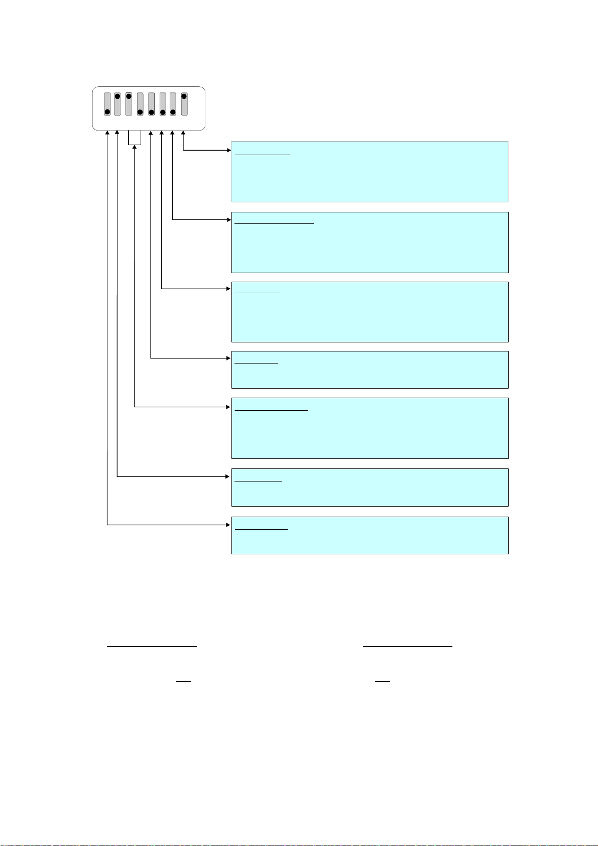
•Selbsttest: Stellen Sie den DIL- Schalter
entsprechend Ihrer Anwendung ein und
schließen Sie das Gerät an. DIL- Schalter 6
zuerst auf ON setzen (Testbetrieb). Gerät
einschalten. Die grüne LED (Betriebs-
spannung) und die gelbe LED (Status)
leuchten zunächst gleichzeitig. Nach
erfolgreichem Selbsttest muß die gelbe LED
erlöschen (ca. 1sec.).
•SSI- Signaltest: Nun den Teach- Taster
einmal betätigen. Die SSI- Datenleitung wird
getestet. Wenn die LED aufleuchtet, ist der
Status korrekt. Wenn die LED nicht
aufleuchtet, müssen die Leitungen Data+ (9)
und Data-(8) vertauscht werden.
Bei der zweiten Betätigung des Tasters wird
in gleicher Weise die SSI- Clockleitung
getestet. Leuchtet die LED, ist der Status
korrekt, andernfalls müssen die Leitungen
Clock+(3) und Clock-(2) vertauscht werden.
Bei einer dritten Betätigung des Tasters geht
die LED wieder aus und der Statustest
beginnt von vorne.
Wenn die Status- LED nach der ersten und
nach der zweiten Betätigung des Tasters
leuchtet, ist der SSI- Status in Ordnung.
Gerät ausschalten und DIL- Schalter 6 auf
OFF stellen (Normalbetrieb).
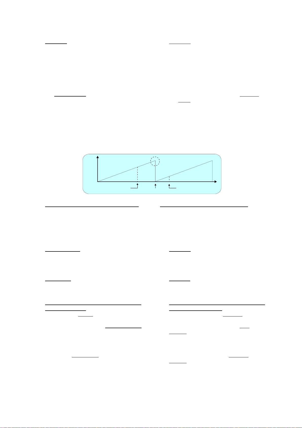
•Skalierung des Analogausgangs mittels
Teach- Funktion:
Gerät erneut einschalten (Schalter 6 OFF)
und Teach- Taster einmal betätigen. Die
gelbe LED blinkt nun langsam und das
Gerät wartet auf das Setzen des
Anfangspunktes. Geber auf die gewünschte
Anfangsposition bringen und Taster erneut
betätigen. Der Anfangswert ist gespeichert.
Die LED blinkt nun schnell und das Gerät
wartet auf das Setzen des Endpunktes.
Geber auf die gewünschte Endposition
bringen und Taster nochmals betätigen. Der
Endpunkt ist gespeichert und die LED
erlischt. Der Analogausgang ist damit auf
den Bereich 0 Volt bis 10 Volt zwischen
Anfangs- und Endposition kalibriert.
8. Setup with SSI absolute encoders
With basic applications, you can use
the Teach feature for commissioning of
the unit. Extended functions need a PC
for setup and are described under
section 11.
•Self Test: Set all DIL switches according
to your application and connect encoder
and power supply to the unit.
Set switch position No. 6 to ON first (test
mode) and power the unit up. The green
LED (power) and the yellow LED (status)
must light both. After a successful self-test,
the yellow LED must switch off again
(approx. 1 sec.)
•SSI signal test: Push the Teach button
one time now. This will verify the SSI Data
lines. The yellow LED must switch on now.
Where it remains off, you need to cross the
input lines Data+ (9) and Data- (8).
The second actuation of the Teach button
will test the SSI Clock lines in the same
manner. Again, the LED must be lit,
otherwise you need to cross the lines
Clock+ (3) and Clock- (2).
The third actuation of the Teach button will
switch off the LED again and restart the
status test cycle.
Where you find your status LED lit after the
first and the second actuation of the
button, your wiring of the encoder is o.k.
Now, power the unit down and set DIL
position 6 to OFF (normal operation).
•Scaling of the analogue output with use
of the Teach function:
Power the unit up again, with DIL position
6 set to OFF. Press the Teach button one
time. The status LED will blink in a slow
sequence now while the unit waits for the
zero position. Move your encoder to
where you like zero output and press the
button again. This stores your zero
definition and the LED will blink in a fast
sequence now while the unit waits for the
full scale position.Move your encoder to
where you desire full scale output and
press the button once more. This stores
your full scale definition and the LED will
switch off. After this Teach procedure, your
analogue output is set to 0 – 10 volts.