ipf DW34312 Series User manual

DW34312x
pressure sensor
MANUAL •Subject to alteration! Version: September 2016
ipf electronic gmbh
•Rosmarter Allee 14 •58762 Altena
│
Tel +49 2351 9365-0 •Fax +49 2351 9365-19
│
1

table of contents
safety instructions page 3
controls and indicating elements page 4
page 5
page 6
page 8
page
8
page 9
page 9
page 10
page 11
page 12
page 12
page 15
page 16
page 17
description of the operating elements
menu / overview
operation modes of the switching outputs
switch-point with release position
switch-point with hysteresis
window function with release position
window function with hysteresis
operating modes
programming
list of parameters
mounting and electrical connection
initial operation / operation
factory settings / technical data
dimensional drawings / list of articles
page 18
MANUAL •Subject to alteration! Version: September 2016
ipf electronic gmbh
•Rosmarter Allee 14 •58762 Altena
│
Tel +49 2351 9365-0 •Fax +49 2351 9365-19
│
2

safety instructions
Read the product description before installing the unit. Ensure that the
product is siutable for your application without any restrictions.
Non-adherence to the operating instructions or technical data can lead to
personal injury and/or damage to property.
In all applications check compliance of the product materials (see technical
data) with the media to be measured.
Do never touch the pressure membrane with the fingers or any other object.
The membrane can be damaged irreparably!
Never use these articles in applications where the safety of a person
depends on their functionality!
MANUAL •Subject to alteration! Version: September 2016
ipf electronic gmbh
•Rosmarter Allee 14 •58762 Altena
│
Tel +49 2351 9365-0 •Fax +49 2351 9365-19
│
3

controls and indicating elements
description function symbol
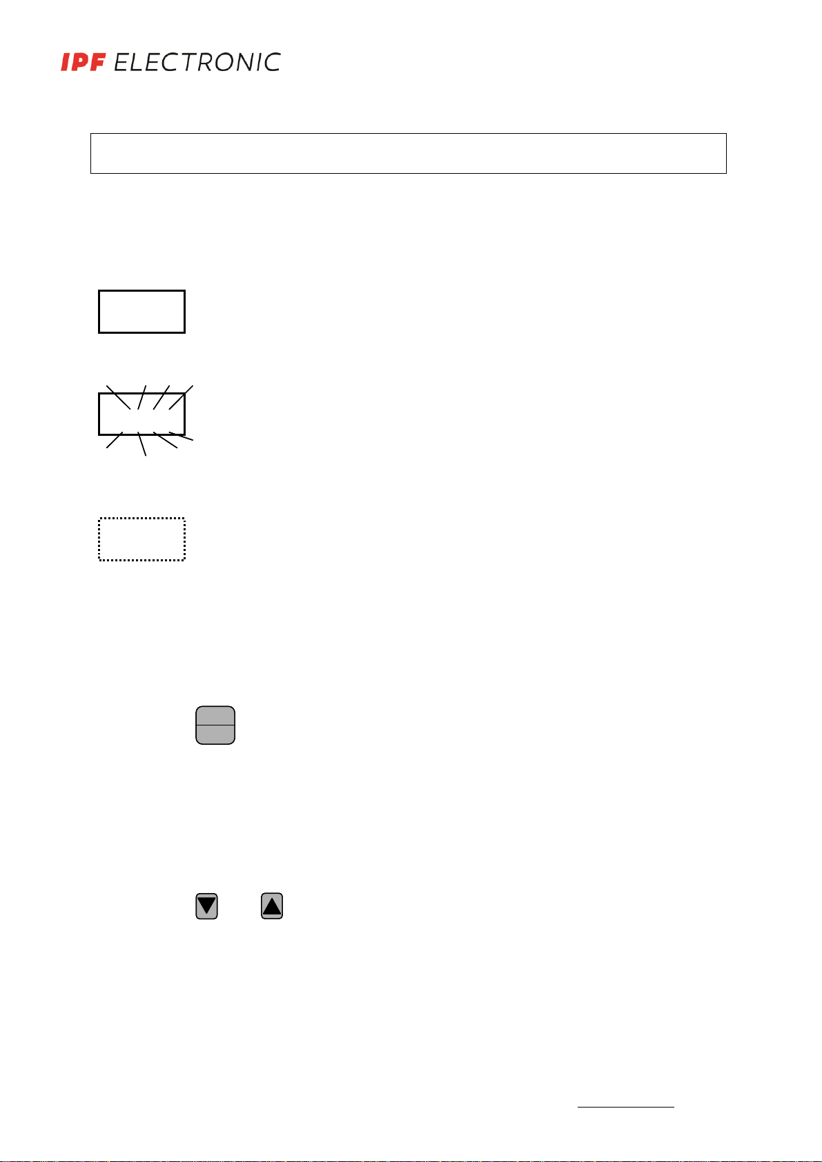
1 4-digit display displays the current system pressure
parameter, parameter values
265.4
2 LED red
S1
displays the switching state of output 1
lights, if the output is switched -
3 LED red
S2
displays the switching state of output 2
lights, if the output is switched -
4 programming button
Enter/ Set
selection of menus and parameters
setting and saving of parameters
Enter
Set
Enter
Set
5 arrow key
up
setting the parameter values
increasing the value
(fast, keep the button pressed
stepwise by pressing the button short)
6 arrow key
down
setting the parameter values
decreasing the value
(fast, keep the button pressed
stepwise by pressing the button short)
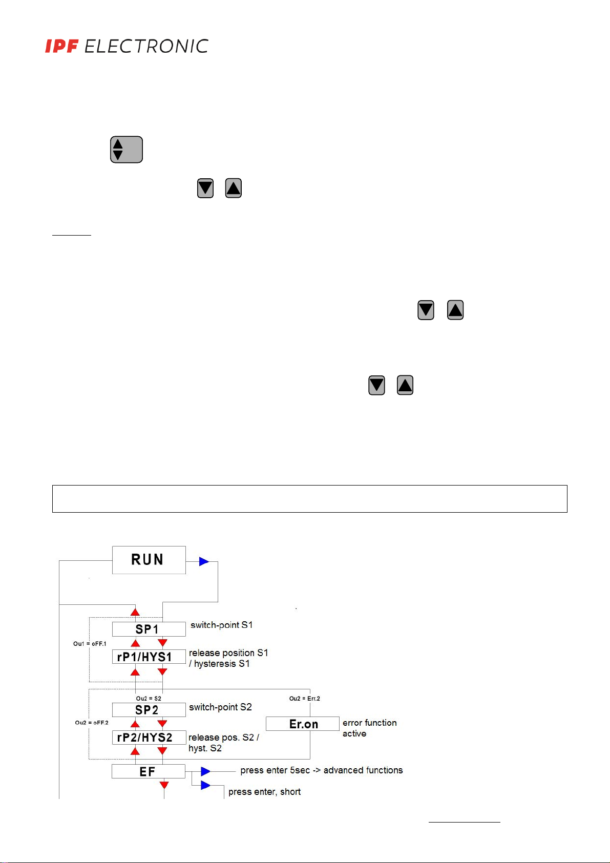
7 ESC finishing programming without saving
key lock: press both the arrow keys at the
same time
ESCESC
MANUAL •Subject to alteration! Version: September 2016
ipf electronic gmbh
•Rosmarter Allee 14 •58762 Altena
│
Tel +49 2351 9365-0 •Fax +49 2351 9365-19
│
4

265.4
265.4265.4
SP.2
description of the operational controls
display
4-digit lighted LED display
symbolic description:
shows the current system pressure (RUN-Mode), menu name, parameters
and parameter values.
blinking display in RUN-Mode: fault report (Error).
3 x blinking in PROGRAMM mode: saving current value after pressing
Enter/Set button.
The indication on the display depends on the programmed function.
If one of these functions is selected in the enhanced Menu, the indication
will be shown on the display.
program button Enter/Set
symbol:
Enter
Set
Enter
Set
Selection of menus and submenus as well as confirming and saving of parameter values.
Short pressing in the RUN-Mode →starting up the base menu.
arrow keys
symbol:
and
Increasing and decreasing the parameter values and scrolling of the menu.
Pressing the button continuously, the value increases or decreases in „fast-forward“
mode. Pushing the button →the value changes step by step.
MANUAL •Subject to alteration! Version: September 2016
ipf electronic gmbh
•Rosmarter Allee 14 •58762 Altena
│
Tel +49 2351 9365-0 •Fax +49 2351 9365-19
│
5

ESC- button
symbol:
ESCESC
Pressing both arrow keys + at the same time results in the ESC function.
With the ESC function you can step backwards inside the menu and parameters
without saving the settings.
In order to leave all menus and submenus please press the ESC-button again and again
until you are back in the RUN-mode.
key lock
If the device is in the RUN-Mode and you press the arrow keys + at the same
time for at least 5 seconds, the key lock will be activated.
The display shows „sLOC“, blinking 3 times.
Now the adjusted settings can be read but not be changed.
For cancelling the key lock please press both arrow keys + for at least 5 seconds
again.
menu / overview
1. level
MANUAL •Subject to alteration! Version: September 2016
ipf electronic gmbh
•Rosmarter Allee 14 •58762 Altena
│
Tel +49 2351 9365-0 •Fax +49 2351 9365-19
│
6

2. level
MANUAL •Subject to alteration! Version: September 2016
ipf electronic gmbh
•Rosmarter Allee 14 •58762 Altena
│
Tel +49 2351 9365-0 •Fax +49 2351 9365-19
│
7

operation modes of the switching outputs
notes:
•The following examples and descriptions of the switching output 1 (SP1) refer to the
switching function „normally open“ (no). If the switching output 1 is set „normally
closed“ (nc) the states are reversed.
•The minimum range between the switching outputs (SP.1 and rSP.1) is 1% of the
nominal pressure; stated by the system.
•The smallest adjustable hysteresis is 1% of the nominal pressure; stated by the sys-
tem.
•All examples are effective for output 2, if this output is defined as switching output
(SP-2) also.
switch-point with release position
programmed parameters: SP.1: 250.0 bar
rP.1:
40.0 bar
output
release position
switch-point
pressure [bar]
An increasing pressure up to SP.1 (e.g. 250bar), switches the output according to the ad-
justed switching function (no or nc). This state remains also for higher pressure.
For decreasing pressure the switching state changes with the pressure value at rP.1 (e.g.
40bar). If SP.1 will be changed, rP.1 remains the same.
The minimum range between SP1 and rSP.1 is 1% of the maximum pressure.
MANUAL •Subject to alteration! Version: September 2016
ipf electronic gmbh
•Rosmarter Allee 14 •58762 Altena
│
Tel +49 2351 9365-0 •Fax +49 2351 9365-19
│
8

switch-point with hysteresis
programmed parameters: SP.1: 50.0 bar
HYS.1: 20.0 bar
output
pressure [bar]
switch-point
An increasing pressure up to SP.1 (e.g. 50bar) switches the output according to the ad-
justed switching function (no or nc). This state remains also for higher pressure.
For decreasing pressure the switching state changes after passing the hysteresis (e.g.
20bar). If SP.1 will be changed, the hysteresis HYS1 remains the same, that is the release
position is (SP.1 – 20)bar.
MANUAL •Subject to alteration! Version: September 2016
ipf electronic gmbh
•Rosmarter Allee 14 •58762 Altena
│
Tel +49 2351 9365-0 •Fax +49 2351 9365-19
│
9

MANUAL •Subject to alteration! Version: September 2016
ipf electronic gmbh
•Rosmarter Allee 14 •58762 Altena
│
Tel +49 2351 9365-0 •Fax +49 2351 9365-19
│
10

operating modes
RUN-mode
Normal operating mode.
At power on the unit is in the Run mode. It carries out its measurement and evaluation
functions and provides output signals according to the set parameters.
The display shows the current system pressure. The red LEDs indicate the switching
state of the outputs.
display mode
Display and setting of switch-points, release positions and hysteresis.
When the Enter/Set button is pressed briefly, the unit passes to the main menu. The in-
ternal sensing, processing and output functions of the unit continue as if in Run mode.
The parameter values can be read and adjusted.
Pressing the arrow key „downwards“ briefly, scrolls through the adjustable parameters.
Pressing the Enter/Set button briefly, indicates the adjusted parameter value.
Pressing the arrow key „downwards“ or „upwards“ briefly, changes the parameter value
step by step. Pressing the arrow key continuous changes the value fast.
Pressing the Enter/Set button safes the adjusted value, the display blinks three times.
The unit now operates with the „new adjusted“ value.
Returning to the RUN-Mode: Press the ESC button.
enhanced menu/ programmimg mode
Setting of the parameter values and programming the main functions.
The unit changes to the programming mode if „EF“ is set in the main menu and the En-
ter/Set button is pressed for at least 5sec.
The internal sensing, processing and output functions of the unit continue as if in Run
mode.
Pressing the arrow key „downwards“briefly, scrolls through the adjustable parameters.
Pressing the Enter/Set button briefly, indicates the adjusted parameter value
Pressing the arrow key „downwards“ or „upwards“ briefly, changes the parameter value
step by step. Pressing the arrow key continuous changes the value fast.
Pressing the Enter/Set button safes the adjusted value, the display blinks three times.
The unit now operates with the „new adjusted“ value.
Returning to the RUN-Mode: Press the ESC button several times.
MANUAL •Subject to alteration! Version: September 2016
ipf electronic gmbh
•Rosmarter Allee 14 •58762 Altena
│
Tel +49 2351 9365-0 •Fax +49 2351 9365-19
│
11

*a flashing point on the display indicates that a value can be changed.
After confirming the set value the displayed value will blink three times.
parameter list
SP1 switch-point S1
HYS1 / rP1 hysteresis S1 / release poosition S1
SP2 switch-point S2
HYS2 / rP2 hysteresis S2 / release position S2
EF This menu item encloses a sub menu which contains further pa-
rameters.
Press the Enter/Set for at least 5sec to get access to these parame-
ters.
rES Reset (getting back to the factory settings)
Press the Enter/Set button at least for 5sec to reset the system.
Thereafter the unit returns into the RUN Mode automatically.
programming
button display description
Enter
Set
Enter
Set 1X SP1
Press the Enter/Set button briefly to get into the main menu.
Press the Enter/Set button again.
The current value for switch-point S1 will be displayed.*
Set the parameter value with the arrow keys.
Confirm the set value with the Enter/Set button.
1X
rP1 /
HYS1
Press the Enter/Set button.
The current value for the release position S1 respectively
the hysteresis will be displayed.*
Set the requested value with the arrow keys.
Confirm the value with the Enter/Set button.
1X
Output 2 is set as switching output SP2 / rP2 respectively
HYS2. Changes can be made as described above.
Output 2 gives an error signal: Er.On
As soon as the Outputs become inactive, EF will be dis-
played.
1X EF
Press Enter/Set or briefly to get into the RUN Mode.
Press the Enter/Set button continuously for min. 5sec to get
into the advanced functions. A point is blinking in the display
as long as the button is pressed.
Changes inside the menu items can be made as described
above. The possible menu items can be seen in the pa-
rameter list.
MANUAL •Subject to alteration! Version: September 2016
ipf electronic gmbh
•Rosmarter Allee 14 •58762 Altena
│
Tel +49 2351 9365-0 •Fax +49 2351 9365-19
│
12

Ou 1 Configuration of output1:
Four switching functions are possible:
SP.HY switch-point / hysteresis
SP.rP switch-point / release position
FE.HY window function / hysteresis
FE. rP window function / release position
oFF.1 output 1 „off“
noc 1
noc 1 is only active if in Ou 1 a switching function is set.
Function of switching output S1:
no.1 (normally open)
nc.1 (normally closed)
ds 1 ds 1 is only active if in Ou 1 a switching function is set.
on-delay timer function S1
dr 1 ds 1 is only active if in Ou 1 a switching function is set.
off-delay timer function S1
Ou 2 Configuration output 2:
Four switching functions, the error signal or 4 analog functions
are possible:
SP.HY switch-point / hysteresis
SP.rP switch-point / release position
FE.HY window function / hysteresis
FE. rP
Err. 2
window function / release position
error signal
oFF.2 output 2 „off“
noc 2 noc 2 is only active if Ou 2 is set as switching function.
Function of switching output S2:
no.2 (normally open)
nc.2 (normally closed)
dS 2 dS 2 is only active if Ou 2 is set as switching function.
ready-on delay-time S2
dr 2
Ou A
dr 2 is only active if Ou 2 is set as switching function.
ready-on delay-time S2
analog output configuration:
4-20 analog signal 4-20mA
0-20 analog signal 0-20mA
20-4 analog signal 20-4mA
20-0 analog signal 20-4mA
0u10 analog signal 0-10V
0u5 analog signal 0-5V
10u0 analog signal 10-0V
5u0 analog signal 5-0V
oFF.A analog output off
MANUAL •Subject to alteration! Version: September 2016
ipf electronic gmbh
•Rosmarter Allee 14 •58762 Altena
│
Tel +49 2351 9365-0 •Fax +49 2351 9365-19
│
13

dAA dAA is only active if in Ou2 an analog signal was set.
Damping the analog output
This function filters peak values of short duration or high fre-
quency.
dAA-value = response time. Period of time between the chang-
ing of the pressure and the analog signal. (unit, seconds).
FOUA
FOUA is only active if in OU 2 aog signal was set. Error
signal of the analog output.
The analog output signal is <3.6mA or >22mA
HI saving the max. pressure value of the system. The highest value
is displayed.
= delete memory
LO Saving the min. pressure value of the system. The lowest value
is displayed.
= delete memory.
CYC counter switching cycles of S!
COF zero-point calibration
The internal measurand (operating value of the sensor) is offset
compared to the real measurand.
adjustment range: +/-10% of the measuring span.
ddIS Damping of the display (Peak-Hold-Time)
FdIS Dislpay functions:
rd rotate display
Ph peak-hold. Temporary display of peak values
Rd. Ph rotate display + peak hold
oFF standard display
EdA
Error display of the analog output.
(for 4…20mA/ 20…4mA only)
FOUA
dAA
dAA is only actice if in Ou A an analog signal was set.
Damping the analog output: This function filters peak values of short
duration or high-frequency
dAA-value = response time. Period of time between the changing of the
pressure and the analog signal in seconds.
FOUA is only active if in Ou A an analog signal was set.
Error signal of the analog output.
The analog output signal is <3.6mA or >22mA
(for 4-20mA/ 20-4mA only)
MANUAL •Subject to alteration! Version: September 2016
ipf electronic gmbh
•Rosmarter Allee 14 •58762 Altena
│
Tel +49 2351 9365-0 •Fax +49 2351 9365-19
│
14

tESt Press Enter/Set button for 5sec, then test-function (no timeout)
With the Test-function you can check the adjusted parameters
without influence for the system.
The display starts with indicating the current pressure.
Due to the arrow keys the displayed value can be increased or
decreased. All parameters react as if the real pressure would
increase or decrease.
Leave the Test Mode with ESC.
END End of enhanced functions.
Press the Enter/Set button twice to get into the RUN mode
again.
The units come with an optical interface that allows all parameters to be set and ad-
justed by a PC or notebook.
The suitable interface cable and Windows-Software can be ordered with the article
number AD000011.
With the Software you are able to adjust all functions described above.
NOTE:
Use a shielded cable socket (e.g. VK205A21), in order to avoid
interfer-ences.
mounting and electrical connection
Before mounting and removing the unit: Make sure that no pressure is applied to the
system.
Mount the pressure sensor DW34 on a G1/2 – process connection.
After mounting the sensor mechanically, the control panel can be rotated by 350°.
Do not touch the opening of the pressure connection with finger or a sharp object.
This causes irreparable damage to the mebrane!
The unit must be connected by a suitably qualified electrician. The national and in-
ternational regulations for the installation of electrical equipment must be observed.
Voltage supply to EN50178.
Disconnect power before connecting the unit as follows:
MANUAL •Subject to alteration! Version: September 2016
ipf electronic gmbh
•Rosmarter Allee 14 •58762 Altena
│
Tel +49 2351 9365-0 •Fax +49 2351 9365-19
│
15

implementing / operation
After mounting, electrical connection and programming, please check the safety of the
unit.
Fault indications during operation
display cause effect on the outputs elemination
OL
overload
exceeding the measuring range
(sensor-limit) > 120%Pnominal
-limit the system pres-
sure to Pnominal.
If necessary use a unit
with higher measure-
ing range
UL
underload
system pressure is lower than
the measuring range
SC1 short-circuit S1 analog output=
error signal*
- check wiring
- check load of S1
SC2 short-circuit S2 analog output=
error signal*
- check wiring
- check load of S2.
SC short-circuit S1 and S2 analog output=
error signal
- check wiring
- check load
ERR sensor defect, internal error
-S1 and S2 are switched
off
- analog output = error
signal*
contact manufacturer
AO
if current output is selected:
analog-output open
if voltage output is selected:
short-circuit or voltage is
applied
- check wiring
- check burden resis-
tance.
NOTE:
If this indication is un-
desired, the menu item
Eda can be set Ed.of.
* the error signal of the analog output appears only, if in Ou2 an analog signal (4...20mA
or 20...4mA) was set.
The error signal (< 3.6mA or >22mA) can be set in menu item FOuA.
MANUAL •Subject to alteration! Version: September 2016
ipf electronic gmbh
•Rosmarter Allee 14 •58762 Altena
│
Tel +49 2351 9365-0 •Fax +49 2351 9365-19
│
16

factory settings
OU 1 SP.rP
OU 2 4 … 20
SP 1 50% of nominal pressure
rP 1 10% of nominal pressure
SP 2 75% of nominal pressure
rP 2 10% of nominal pressure
Technical Data
pressure range [bar]
excess pressure [bar]
pressure detection
operating voltage UB
voltage drop
current consumption
switching outputs
time delay
adjustment range switch-
point release position
sampling frequency
repeatability
current output
burden
voltage output
burden
error recognition
rise time
damping
linearity deviation system
pressure display
switching function display
display damping
operating temperature
temperature drift
conn. to pressure system
sensor head material
housing material
degree of protection
electrical connection
optical interface
see list of articles
150% of nominal pressure (PN)
peak value memory every 2msec (display via PC)
12 ... 32V DC, reverse polarity protection
(15 ... 32V DC, if operated with voltage output)
< 2V
< 60mA
2 x pnp-switching, no/nc, 1A short-circuit protection
0 to 20sec, on-/off-delay adjustable separately
1 ... 100% of PN,
0 ... 99% of PN
max. 125Hz
< ±0.1% of accumulated value
0/4 ... 20mA, 20 ... 0/4mA, start- and end-point selectable max. RL
max. RL [Ω] = (UB-8V) / 20mA
0 ... 5/10V, 5/10 ... 0V, start- and end point selectable
min. 5kΩ
analog outp.if line breakage (current) - short-circuit (voltage, ≥1V)
5msec (10% ... 90% of PN)
0 ... 20sec, adjustable
max. ±0.25% of PN
4 x 7 segment LED-display
2x LED red
0 ... 20sec, adjustable
-20°C ... +80°C
< ±0.2% / 10K (-10°C ... +70°C)
G1/2A, SW 27
stainless steel 1.4435
PA6.6, polyester
IP65 acc. EN 60529
M12 connector,8-pin
9600 Baud, via opto-adapter on USB-Port
optical interface 9600 Baud, via optical adapter at USB-port
MANUAL •Subject to alteration! Version: September 2016
ipf electronic gmbh
•Rosmarter Allee 14 •58762 Altena
│
Tel +49 2351 9365-0 •Fax +49 2351 9365-19
│
17

dimensional drawings
fig.1: DW34xxxx
list of articles
article-no design description housing voltage output curre
nt connection fig.
DW34312D
34-G1/2A
10bar, stainless steel polyester/V4A 12-32V DC pnp,no/nc,analog 2x1A M12-conn4pin 2
DW34312F
34-G1/2A
50bar, stainless steel polyester/V4A 12-32V DC pnp,no/nc,analog 2x1A M12-conn4pin 2
DW343124
34-G1/2A
100bar, stainless steel polyester/V4A 12-32V DC pnp,no/nc,analog 2x1A M12-conn4pin 2
DW34312G
34-G1/2A
200bar, stainless steel polyester/V4A 12-32V DC pnp,no/nc,analog 2x1A M12-conn4pin 2
DW343126
34-G1/2A
400bar, stainless steel polyester/V4A 12-32V DC pnp,no/nc,analog 2x1A M12-conn4pin
2
DW343127
34-G1/2A
600bar, stainless steel polyester/V4A 12-32V DC pnp,no/nc,analog 2x1A M12-conn4pin
2
DW34312K 34-G1/2A -1…+10bar, stainless st. polyester/V4A 12-32V DC pnp,no/nc,analog 2x1A M12-conn4pin
2
AY000060 accessory mounting clip w/o
AD000011 accessory
optical interface connection USB, software
1.5m cable w/o
Other pressure ranges and versions on request.
MANUAL •Subject to alteration! Version: September 2016
ipf electronic gmbh
•Rosmarter Allee 14 •58762 Altena
│
Tel +49 2351 9365-0 •Fax +49 2351 9365-19
│
18
This manual suits for next models
7
Table of contents
Other ipf Accessories manuals