VCP-QVGA-02
Electrical specifications (typical values unless otherwise stated)
Power supply (VDD) 3.5 V to 5.3 V DC ( ia system connector)
Supply current in Sleep mode 75 μA
Temperature sensor accuracy ±0.5 °C typ., ±3 °C max.
Dimensions 120 mm x 80 mm x 23 mm
Weight 61 g
Temperature range 0 °C to +70 °C
Absolute maximum ratings
Stresses abo e those alues may cause permanent damage to the de ice. Exposure to maximum rating conditions
for extended periods may affect de ice reliability.
Supply oltage (VCC): 5.8 V DC
Storage temperature: -30 °C to +80 °C
Hardware
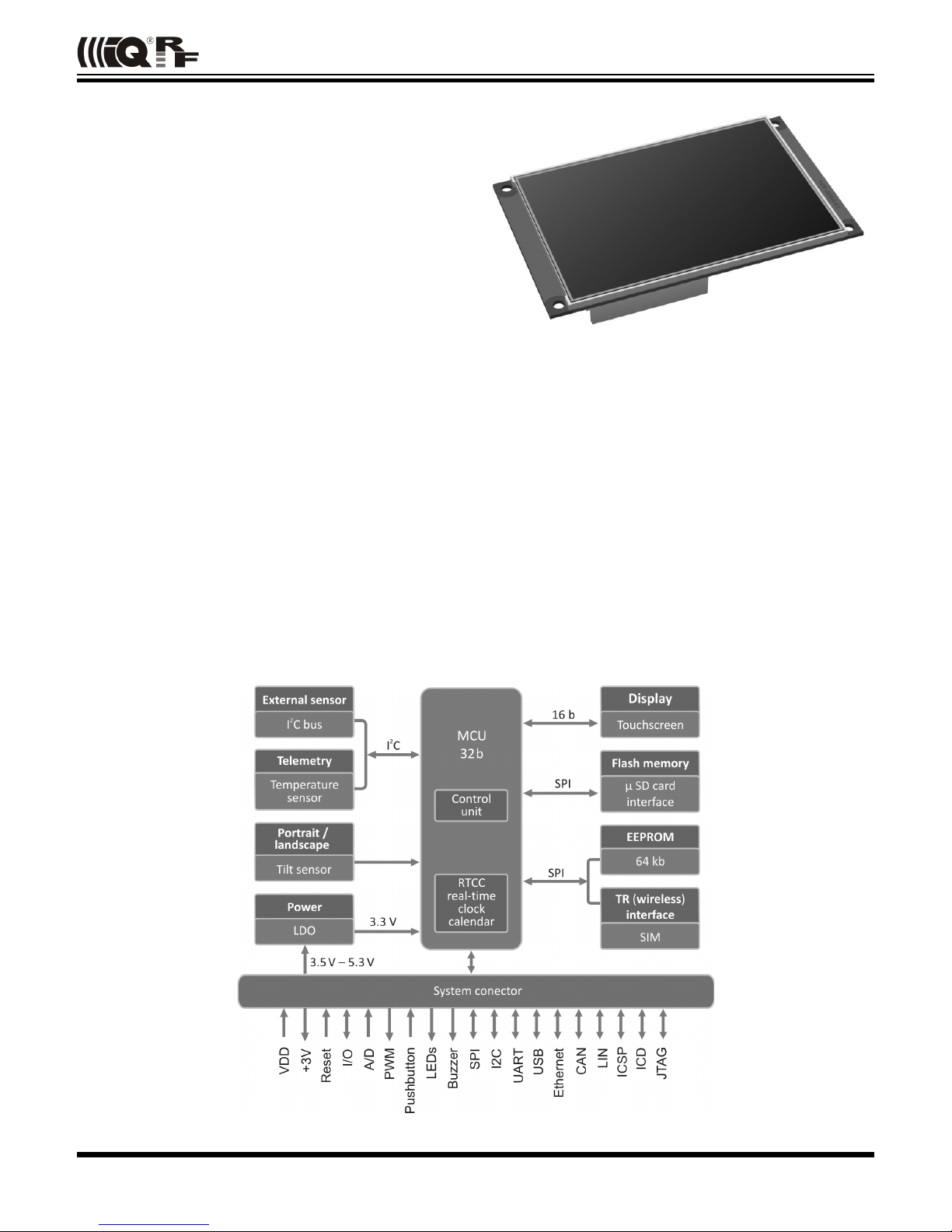
VCP-QVGA-02 is a generic equipment, i.e. the hardware is fixed and the user can realize specific functionality by
software only. See DS-QVGA-02 documentation and demo SW for details.
Power supply
VCP-QVGA-02 is intended to be supplied by external power supply (VDD) connected ia system connector. This is
con erted to 3.3 V by internal LDO regulator.
MCU
VCP is controlled by the 32b microcontroller PIC32MX795F512LPL, up to 80 MHz, 100 pins.
Oscillators
MCU is clocked by external 16 MHz crystal oscillator which allows to reach up to 80 MHz using the internal PLL. For
minimized power consumption, RTCC operation in Sleep mode etc. secondary crystal oscillator 32.768 kHz is a ailable.
Reset
VCP reset (initialization/starting-up) can be in oked by low le el on the MCLR MCU pin ia system connector or by
software.
Sleep mode
This is intended for current consumption minimizing, especially in idle or while supplied from an accumulator. It is possible
to switch off all functions and peripherals by software.
VGA display
Display / touchscreen DI-QVGA-3.2-02 with diagonal 3.2“, 320x240 pixels RGB, 262144 colors (graphic library uses 65535
colors only), QVGA TFT LCD, transmissi e, with LED backlight and 16b data bus.
Proper display functionality requires a calibration (setting the touch sensors in accordance to display pixels) to compensate
ariations in parameters due to temperature, tolerance of parts and so on. The GW has the display factory calibrated and
this can also be done in application software whene er needed (3x3 touches in places indicated by an arrow). The
calibration is stored to the EEPROM. See the Demo software.
LED backlight can be switched on/off by the software.
EEPROM memory
Capacity: 64 kb, serial interface SPI (shared with the TR module) 1 000 000 erase/write cycles (typ.).
Micro SD interface
The VCP has the SPI interface to standard Flash memory micro SD card. The memory can be put to the standby mode by
SW. SD connector (Hirose DM3AT-SF-PEJ) is included if the VCP is a part of the DS-QVGA-02 de elopment set only.
© 2011 MICRORISC s.r.o. www.iqrf.org MNVCPQVGA02_110810 Page 3