iQtronic IQSocket IQTS-IP200 User manual

User guide www.IQtronic.com
`
User
Guide
IQSocket IQTS-IP200
Version v.0 rev0

User guide www.IQtronic.com
Important information........................................................................... 3
1Introduction.................................................................... 4
1.1 Product features ........................................................................... 5
2Installation ..................................................................... 6
2.1 Wiring the IQsocket IQTS-IP200 ..................................................... 6
2.2 Powering IQTS-IP200 On ............................................................... 7
3Managing IQTS-IP200..................................................... 8
3.1 Setting IP addresses ..................................................................... 8
3.2 Managing by web browser.............................................................. 8
3.2.1 Status page.......................................................................... 9
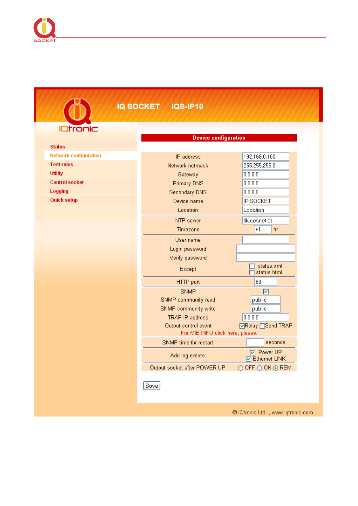
3.2.2 Network configuration...........................................................10
3.2.3 Test rules –watchdog function...............................................13
3.2.4 Utility .................................................................................17
3.2.5 Control socket......................................................................19
3.2.6 Logging...............................................................................22
3.2.7 Quick setup .........................................................................23
3.2.8 Automatic correction of parameter values ...............................24
3.3 SNMP .........................................................................................24
3.3.1 Example - using SNMP under OS Windows ..............................26
3.3.2 Example - using SNMP under OS Linux ...................................28
3.3.3 SNMP trap example ..............................................................28
3.4 Status data in XML format.............................................................29
3.5 IQLocator utility...........................................................................29
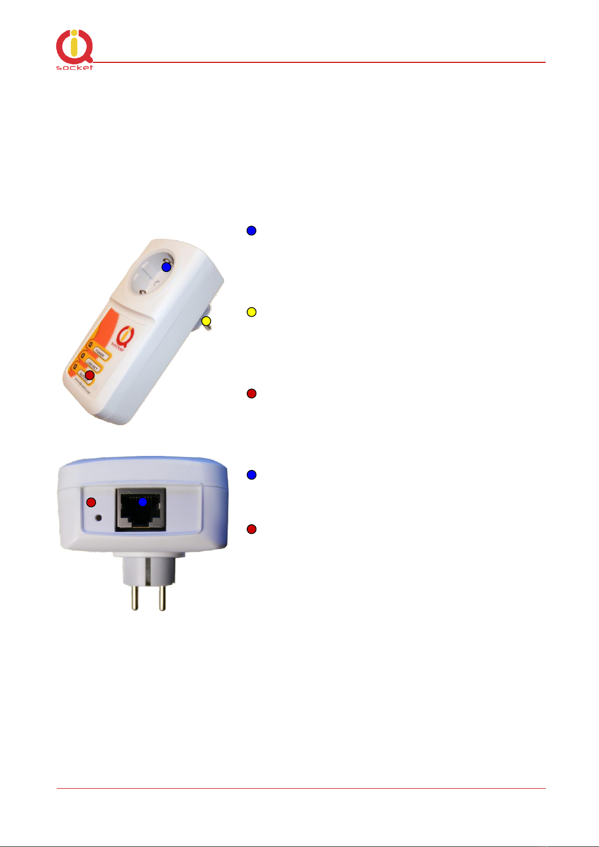
4Indicators ..................................................................... 32
5Output socket wiring diagram ....................................... 33
6Reset to factory default using push button ................... 33
7Technical specification .................................................. 34
7.1 Operation, maintenance and safety recommendations ......................35
8Ordering and accessories .............................................. 36

©2015 IQtronic technologies Europe s.r.o.
Page 3 of 36
Important information
Every effort has been taken to ensure the accuracy of this document, however
we do not accept responsibility for damage, injury, loss or expense resulting
from errors and omissions, and we reserve the right of amendment without
further notice.
WARNING: This product is not designed for use in, and should not be used for,
medical applications.
The product doesn’t guarantee safe power source disconnection, only functional
switching of power is performed.
The product contains no serviceable parts, or internal adjustments. No attempt
must be made to repair this product. Faulty units must be returned to supplier
for repair. Improper use, disassembling or product modification causes
warranty loss.

©2015 IQtronic technologies Europe s.r.o.
Page 4 of 36
1Introduction
IQsocket IQTS-IP200 is a member of family of intelligent power sockets brought
to you by IQtronic, Ltd.
IQsocket IQTS-IP200 allows you to control of any electric appliance connected
to the device’s socket remotely over any IP network, including internet. You can
use for this purpose any device supporting internet browser (HTTP protocol)
such as PC, smartphone etc) or using SNMP protocol.
Output power socket: Connect your
electric appliance here. This socket is
intelligent, can be controlled remotely,
manually or automatically (scheduler).
Power plug: Input of AC power for
product and also for connected
appliance. Fits into electric
socket/outlet.
LED indicators: Inform you about
device status.
RJ-45 socket: Connect it into your
Ethernet network
Push button: For turning on/ off
power socket manually or resetting
configuration to factory default values.
Besides controlling of the socket via IP protocol, IQsocket IQTS-IP200 is
equipped with a choice of useful functions, including:
Push button for manual control of the socket
Watch dog function based on evaluation of ICMP packet loss
Time scheduler function, allowing switching on/off your appliance based on
day of week and time.

©2015 IQtronic technologies Europe s.r.o.
Page 5 of 36
1.1 Product features
In general, IQsocket IQTS-IP200 has following features:
Controlling (turn on, turn off; restart by cutting power for short time)
of any electric appliance connected to the switched socket by HTTP and
SNMP protocols or manually by pressing pushbutton on IQTS-IP200
body
Configuring IQTS-IP200 parameters by HTTP or SNMP protocols,
password protected
XML and HTML status page, can be excluded from password protection,
for easier integration with your web applications
Can send SNMP traps
IQLocator configuration utility allowing to autodiscovery your IQsocket
devices within LAN network, setup IP address and upgrade firmware
Automatic control based on evaluation of ICMP packet loss with up to
three independent rules –watchdog function
Automatic control based on day of week and time –scheduler function
Real time clock synchronized using NTP protocol
On board temperature sensor to monitor internal temperature
Support remote firmware upgrade
Event log storing up to last 50 events, such as socket on/off changes,
device startups, LAN port connectivity, firmware upgrade etc.
Tiny footprint firmware is efficiently coded in C/assembler, there is no
Linux or other operating system inside, so startup times are really
short (<3sec) and tcpip stack is clean with no hidden bugs ;-)

©2015 IQtronic technologies Europe s.r.o.
Page 6 of 36
2Installation
Before starting installation, please read this manual and take into account
Important information section at beginning of this manual.
2.1 Wiring the IQsocket IQTS-IP200
Wiring is intuitive, simply wire RJ-45 jack into your Ethernet network using
cross cable, then connect your electric appliance to the device’s socket and
plug the IQTS-IP200 into a free electric socket.
Controlled power socket: Connect
your electric appliance here.
Power plug: Plug the IQTS-IP200 into
an electrical socket.
RJ-45 socket: For connecting IQTS-
IP200 with your Ethernet network.
Note…
Both the socket and the plug of the IQTS-IP200 follow the same
international standard and nominal voltage rating. Ensure you
ordered proper international version of the IQTS-IP200 suitable
for your country
WARNING!
Please respect maximum current rating of switched socket -
16A for load. Do not overload your IQTS-IP200, as this may
damage or shorten life span of the internal switching relay,
which is not covered by warranty. It is recommended to use
external contactor in case of higher current is required and/or
capacitive/inductive load will be used.

©2015 IQtronic technologies Europe s.r.o.
Page 7 of 36
2.2 Powering IQTS-IP200 On
Once you plug your IQsocket IQTS-IP200 into a live electric socket, it become
powered on and starts operation.
You can verify it by observing status of the LEDs:
Once AC power is connected, all three LED indicators will blink shortly
and internal self-test is performed. Then, if everything is ok, the Power
LED (Red) will blink every second.
LINK/ACT (Green) –solid light indicated established Ethernet link,
blanked for short time when an Ethernet activity occurs
The Output LED (Yellow) indicates state of output socket. Sold light
means socket is active –appliance plugged into the output socket is
operating and vice versa.
Please see chapter 3.5 for more information on LED indicators.
Your IQTS-IP200 is now ready for use.

©2015 IQtronic technologies Europe s.r.o.
Page 8 of 36
3Managing IQTS-IP200
This chapter guides you through management and configuration of IQTS-IP200.
Your IQsocket IQTS-IP200 is equipped with an internal web server, which
provides an easy to use, intuitive and convenient way of management. You can
both set up configuration and operation parameters and get information about
device’s status. There is also support for SNMP protocol, allowing to integrate
your IQTS-IP200 into any SNMP management suite.
In order to access the web interface, it is necessary to setup IP network
address on your PC properly.
3.1 Setting IP addresses
Default IP address of the IQsocket IQTS-IP200 is 192.168.0.100, network
mask 255.255.255.0.
In order to access your IQTS-IP200, it is necessary to setup IP address of your
computer, connected to the same Ethernet network as the IQTS-IP200
properly –in this case set the IP address of the network adapter to
192.168.11, mask 255.255.255.0.
You can also change the IP address of your IQTS-IP200 using IQLocator utility,
see chapter 3.5 for more information.
3.2 Managing by web browser
Once you have properly set IP address of your PC, open the address of your
IQTS-IP200 (default 192.168.0.100) in your favorite internet browser:
If everything is ok, status page will be displayed.

©2015 IQtronic technologies Europe s.r.o.
Page 9 of 36
3.2.1 Status page
Provides summary of device status:
Explanation of parameters:
Section System information provide basic status information, such as Device
name and Location, info on time, firmware version, Ethernet MAC address and
temperature reading of internal temperature sensor.
Section Last event provides date/time of last change of socket state and
current socket state.
Section Rules status informs about currently active automatic rules evaluating
ICMP packet loss to chosen hosts.

©2015 IQtronic technologies Europe s.r.o.
Page 10 of 36
3.2.2 Network configuration
Here you can configure networking and security parameters:
Explanation of parameters:

©2015 IQtronic technologies Europe s.r.o.
Page 11 of 36
IP address
You can setup IP networking parameters such as IP address, Network mask
Default Gateway, DNS servers; please ensure to enter proper values. Please
note it is necessary to define a fixed IP address even if case you are using a
DHCP environment.
Note…
When your local network is using private addresses behind
a NAT router and you would like to make your IQTS-IP200
accessible from the Internet, it is necessary to setup port
mapping (forwarding, server rule) in your router for the IP
address assigned to IQTS-IP200 and selected ports, e.g.
port TCP 80 for accessing web interface.
SOHO example: Your network contains a modem/router with NAT for internet
access, having IP address 192.168.1.254. Simply find an unused IP address
from the private network range it use (192.168.1.1-192.168.1.253) e.g.
192.168.1.200, double check it is not used e.g. by using Ping command from
your PC:
C:\>ping 192.168.1.200
Pinging 192.168.1.200 with 32 bytes of data:
Request timed out.
Then assign the 192.168.1.200 to the IQTS-IP200 by either IQLocator utility or
by web interface and use address of the router (192.168.1.254) in both
Gateway and DNS fields.
NTP setup
IQTS-IP200 can synchronize its clock from an NTP (Network Time Protocol)
server, please don’t forget also to define time zone. Please note NTP feature
will work only if IQTS-IP200 will have access to the Internet.
Note…
It is highly recommended define NTP properly and allow
your IQTS-IP200 accessing the Internet; otherwise
logging and scheduler feature can’t work properly.

©2015 IQtronic technologies Europe s.r.o.
Page 12 of 36
Password protection
You can change/define a login username and password for protecting access to
web interface. It comes with no password by default.
Note…
If you want to disable password protection, enter blank
login password.
You can also activate exception from password protection for pages status.xml
and/or status/html –when exceptions are active, those pages will be then
always available without password, which is useful for further processing of the
status information e.g. by scripts.
HTTP port
It is possible to change port for the web interface from default value 80 by
entering new value to HTTP port field.
SNMP
SNMP can be deactivated by unchecking the SNMP checkbox, it is active by
default. You can change passwords for SNMP read and write communities
(default value is “public”). When there is an output control event resulting from
assessment of automatic packet loss rules –the watchdog feature; IQTS-IP200
can send SNMP trap messages to defined IP address besides operating the
relay of the socket, simply check particular check boxes Relay and/or Send
TRAP.
The SNMP time for restart defines how long is socket turned off when restart
command is issued via SNMP.
Add log events
You can select, which events to write into the event log: Power UP will write
event at every device startup and time has been successfully synchronized
from NTP server; Ethernet LINK will write event at every time when Ethernet
link has been established.
Output socket state after startup
You can choice which state will have output socket after device will be powered
on: to be off, on, or to remember last state before device has been turned
off/power has been lost.

©2015 IQtronic technologies Europe s.r.o.
Page 13 of 36
3.2.3 Test rules –watchdog function
You can configure here automatic watch dog function based on assessment of
ICMP packet lost to selected IP host:
Basically, you can define up to three test rules, two with numerical IP address
of evaluated host, third rule can be defined using host name, and it’s IP
address will be resolved via DNS. Each rule is sending periodically ICMP test
packets to the host and when number of received ICMP replies is lower than
allowed packet loss, rule will generate request for output control event, which
can lead to restart of the output socket, sending of SNMP trap or both,
depending on configuration. Finally, output control event is performed using

©2015 IQtronic technologies Europe s.r.o.
Page 14 of 36
logical OR or logical AND operations over the results (output control event
requests) of particular rules.
Defining rules
Each rule can be enabled or disabled by checking the checkbox. Enter IP
address (Rule 1, Rule 2) or host name in case of the Rule 3, then size of ICMP
frames, maximum allowed packet loss in % and Packet timeout interval, time
how long will device wait for answers from the host –ICMP answers coming
later that the Packet timeout will be considered as lost.
Note…
If you set Packet timeout to 0 (zero) value, device will use
the value of Interval for send test packet as the Packet
timeout interval.
Rules evaluation
You can define periodicity of sending test ICMP packets by entering it into
Interval for send test packet field with allowed range 2-20 seconds.
Interval for next test is time delay till testing will begin after device has been
started up or a rule has been activated (packet loss to a host detected).
You can limit maximum number of consecutive restart attempts by setting
Maximum consecutive restarts parameter to prevent continuous restarting e.g.
if there is a serious problem preventing target host to be recovered back by a
restart via power cycling.
Hold restart for - defines time interval (10-600s) for waiting to connection
recovery. If also this (interval, delay) expires, output socket will be restarted.
It is also possible to cancel (this)
action by SNMP packet.

©2015 IQtronic technologies Europe s.r.o.
Page 15 of 36
Restart socket hold time determines time interval how long is cut power of the
output socket during a restart attempt.
Number of packets to evaluate represents how many test packets is used for
evaluation of packet loss.
Rules evaluation allows to choose when an output control event (restart and/or
SNMP trap) will be performed –in case of selected OR, it will be performed
when ANY from rules is positive; while AND require that ALL rules must be
positive.

©2015 IQtronic technologies Europe s.r.o.
Page 16 of 36
Diagram of rules evaluation
All referenced values come from Test rules settings page. Request means
testing ICMP packets sent to the target host; response means received ICMP
answers from the target host.

©2015 IQtronic technologies Europe s.r.o.
Page 17 of 36
3.2.4 Utility
This page gives you possibility to restore factory default configuration, reboot
device, upgrade firmware and clear statistics data:
Restoring default configuration
Restore default configuration will revert all settings to the factory default
values. It is necessary to reboot the device in order to activate new values
using Reboot button:

©2015 IQtronic technologies Europe s.r.o.
Page 18 of 36
Clearing statistics
Clear statistic data will erase all collected statistics data displayed in Status
page.
Firmware upgrade
Using Browse button select file containing new firmware and then click to
Upload. Upgrade process will take about 50 seconds, which is indicated by fast
blinking of the Power LED (red) and following message will be displayed I case
of success:
In case of an error will be detected, following message will be displayed:
Note…
You can also upgrade firmware using IQLocator utility,
please see chapter 3.5 for more information.
WARNING!
Do not remove power during a firmware upgrade process, as it
can render your device inoperational!

©2015 IQtronic technologies Europe s.r.o.
Page 19 of 36
3.2.5 Control socket
Here you can control the output socket manually and schedule automatic
actions based on date/time.
Socket status
Top of the page contains status row displaying current status of the socket:

©2015 IQtronic technologies Europe s.r.o.
Page 20 of 36
Manual control
Simply click to the buttons to turn on, turn off and restart (change current
state to opposite one temporary for given number of seconds).
Scheduler
This feature allows you to schedule output socket status, up to 50 records are
supported.
Scheduler function use date/time synchronized by NTP protocol, so your IQTS-
IP200 must have access to the Internet (or to an NTP server located within
your private network), see also chapter 3.2.2.
Each scheduler record defines target socket state at given time. It is allowed to
manually control the socket while scheduler is active –each change is done
only at particular time.
Each scheduler record is having following structure:
DOW,…DOW,HH:MM, action
Where:
oDOW means Day of week, coded as first two letters of English day
names: Mo, Tu, We, Th, Fr, Sa, Su;
oHH:MM means time in form of hour:minute in 24h format;
oAction means target socket state –off, on.
Example
Enter following rows:
Mo,Tu,We,Th,Fr,Sa,Su,20:00,Off by clicking to Save button
Mo,Tu,We,Th,Fr,Sa,Su,21:00,On by clicking to Save button
and then activate scheduler by clicking to checkbox Enable scheduler
Table of contents
Other iQtronic Accessories manuals
Popular Accessories manuals by other brands

OCEANAIRE
OCEANAIRE 2OAC Series Engineering, installation and service manual

V-tech
V-tech IS7121 installation guide

TScale
TScale T28 Operation manual

Goldline
Goldline AQL2-BASE-RF Installation and operation manual

1 BY ONE
1 BY ONE O00QH-0512 user manual

R/Evolution
R/Evolution RNET-OCC-HV-P-CM Specifications and installation