First Heating WIST NG User manual

Infrared Panel Heater
WIST NG / WIST Elegant NG
Wireless Switching Unit
RFSFH-61
Wireless Temperature Controller
RFTC-50
2 3
RFTC-50
:
Characteristics
Wireless Switching Unit RFSFH-61
•The RFSFH-61 is a wireless switching unit with one output designed to control WIST NG / WIST Elegant NG heating panels with the
following features:
-TRIAC switching element to ensure silent switching of the heating panel.
•Maximum contact load of 5.65 A / 1300 VA / AC1.
•Designed for wireless communication with the RFTC-50 temperature controller which sends commands to switch the unit on or o
based on the current set point temperature.
•Can operate in ambient temperatures of +70 °C ± 5 °C. The duralumin covered electronics are designed specically for use with WIST
NG / WIST Elegant NG heating panels and also serve to cool the switching element.
•It is necessary to use a power cable designed for higher-temperature environments. This power cable is included.
•A switch is located on the side of the electronics housing to turn the ower supply on or o.
• The current operating status of the unit is indicated by LEDs.
• A synchronization button is used to pair up to four units with the RFTC-50 wireless temperature controller.
• A unique HW address is engraved on the cover of the RFSFH-61.
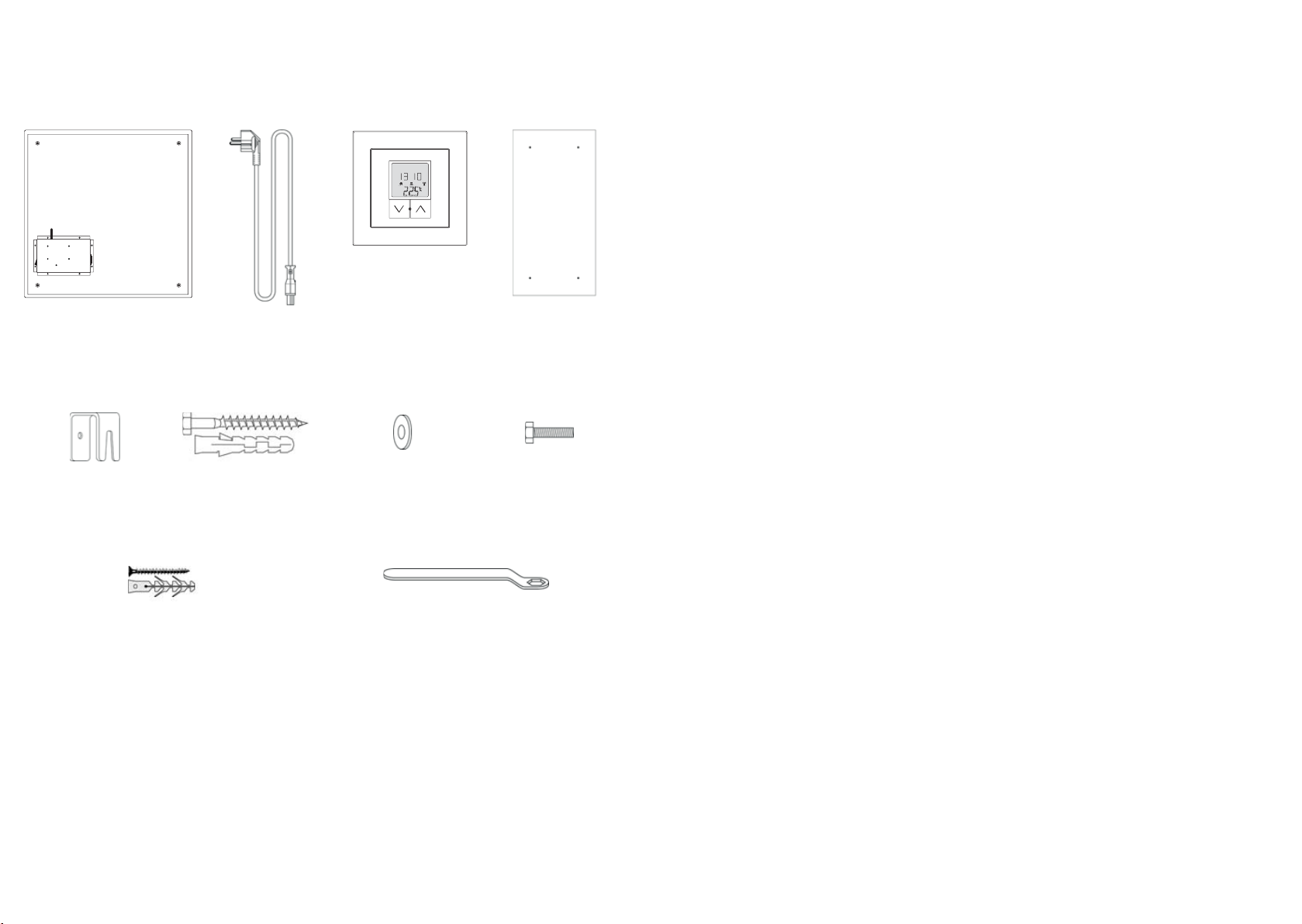
Package contents
Heating Panel with
Wireless Switching Unit RFSFH-61
Power Cable
(2m)
Wireless Temperature Controller
RFTC-50
Installation Template
Screws/ Plugs for Wall
(4x)
Mounting Bracket Screws
(4x)
Screws/ Plugs for Thermostat
(2x)
Mounting Brackets
(4x)
Washers
(4x)
10mm Wrench
(1x)
•The digital wireless RFTC-50 programmable thermostat is a simple solution for controlling temperature in a room or the whole house.
The RFTC-50 has the option to set heating programs by day of the week / time period and has the following features:
- Senses room temperature and sends commands based on the current set point temperature to the RFSFH-61 switching unit. The
RFSFH-61 is integrated with WIST NG / WIST Elegant NG panels. To control BASIC series heating panels, the RFSA-61, RFUS-61 or
RFSC-61 switching actuators can be used, which are also supported by the RFTC-50.
•Can control up to four panels simultaneously.
•Temperature is controlled by using the UP / DOWN buttons.
•Symbols (current and desired temperature, battery status, currently selected mode, etc.) are displayed on the LCD display.
•Supports the following modes: automatic, manual, holiday, o.
•Powered by batteries (2x AAA 1.5V). Batteries included.
•The rear bracket on the device enables installation anywhere in the room.
•The controller is integrated into the LOGUS90 device series, giving the user the opportunity to use the same design for switches (control
of lighting, shading, drawers, etc.), temperature controllers and sockets throughout the house. LOGUS90 oers various frames (glass,
wood, stone, metal) with the option of placement in multiple frames
Wireless Temperature Controller RFTC-50
Infrared Panel Heater WIST NG / WIST Elegant NG
• FIRST Heating panels are a modern heating solution for homes, hotels, oces, and other indoor locations.
• WIST NG / WIST Elegant NG panels produce radiant heat which creates a pleasant feeling of warmth and comfort throughout the
interior. Radiant heating produces minimal air circulation which promotes a cleaner environment particularly well suited for people
with allergies. Radiant heat also makes it possible to heat a room to about 2°C less than with a standard convection system, while still
providing the same level of thermal comfort.
• WIST Series NG / WIST Elegant NG heating panels are equipped with a built-in wireless RFSFH-61 receiver and controlled with the
wireless, battery-operated RFTC-50 thermostat. The panel also has a power switch and is supplied with a socket and 2m power cable.
• WIST Elegant NG panels are frameless with smooth-edged glass, and WIST NG panels are framed with aluminum proles. The standard
version for both models is white. They also may be supplied in RAL colors or printed individual photos/graphics.
• The surface temperature of WIST NG and WIST Elegant NG panels will not exceed 125°C. This allows the panels to be placed either on
walls, ceilings, or vertical stands.

4 5
0 6 12 18 24
Prog AM
°C
Auto PM
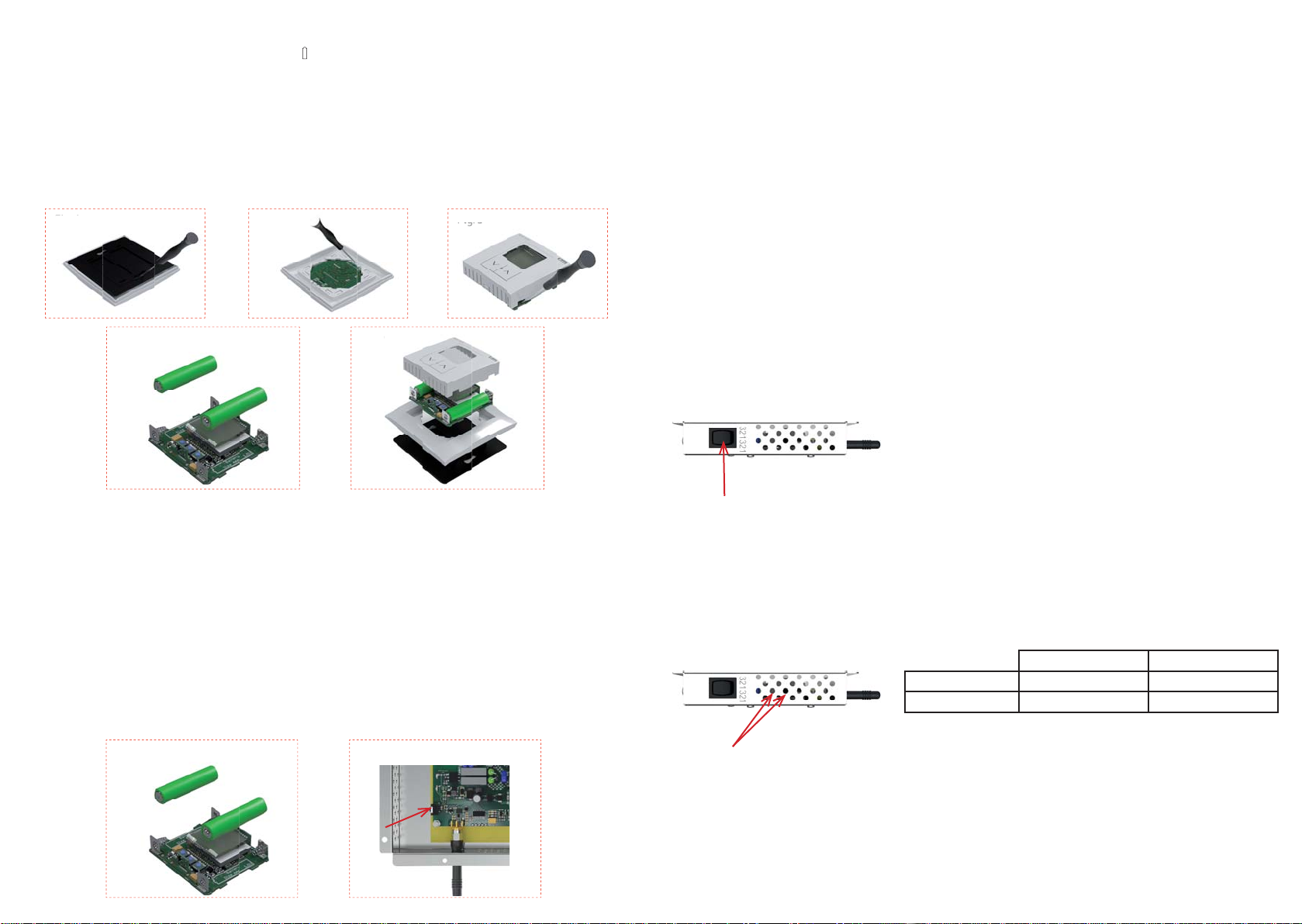
Back panel
HW address
Connector for power cable
Antenna
ON/OFF switch
Description of device RFSFH-61
Antenna
The synchronization
button
LED indicators
ON/OFF switch Connector for power cable
Front panel
Symbols:
- setting the time
- locking the menu item or program
- manual mode
- setting the temperature - mode switched o - no symbol
- output switched on when selecting heating function
- output switched on when selecting cooling function
- displays in the case of low battery voltage
- vacation mode
- constantly illuminated - connection with all actuators successful
- ashing - connection successful only with certain actuators
- not illuminated - connection unsuccessful with all actuators
short press
(< 2 s)
Control button
^
Control button
^
Program button
switching menu items, changing value switching menu items, changing value
closing menu, after closing the menu
communication with actuators is performed
the default display indicates the update
of the actuator status (e.g. upon actuator
power failure)
long press
(> 2 s)
Control button ^Control button
^
Program button
unlocking the menu item or time program
for changing refusal of changed value, return to
original value and locking of the menu
item or program
upon default display entry to the menu
conrmation of changed value after
setting and locking of the menu item
or program
Buttons control
Display of the day of the week Current time in selected
format 12/24
Automatic mode
Description of display
Display the day of the week
Current temperature
Control button (
^
/
^
)
Current time in selected format
12/24
Control button (
^
/ ^)
Program button ( / )
Description of device RFTC-50
Description of device
Note: a symbol is displayed when the batteries are running low The dead battery indicator shows that the voltage is insu cient for
reliable communication with a paired actuator(s).
6 7
NOTE: The RFSFH-61 (panel receiver) is paired with the thermostat (RFTC-50) at manufacture when delivered as a packaged set. The
following procedure is unnecessary in most cases.
The RFTC-50 can easily access the RFSFH-61:
- The panel must be connected to the mains and switched on.
- Immediately after inserting the batteries into the thermostat, press and hold the middle (program) and the right ( ^ ) buttons for
three seconds on the RTFTC-50 wireless controller. LRN will appear on the display (Fig. 6).
- Use a non-conductive, insulated tool with a diameter of less than 4mm to prevent electrical shock when pressing the synchronization
button. Pressing the synchronization button on the RFSFH-61 (Fig. 7) will then pair both units. This is signaled by the RFTC-50
restarting and displaying the hardware address of the paired unit.
The paired RFSFH-61 actuator is saved to position number 1 in the RFTC-50.
- This procedure cannot be repeated at another position. It is primarily used only during assembly at the manufacturer before
shipment to the customer. To pair additional actuators/panels to other positions, the standard hardware addressing procedure is
described later in this manual (Entering the settings menu, page 10).
- Low battery power is indicated by displaying a battery icon .
- Use a screwdriver to remove the back plate (Fig.1).
- Use a screwdriver to carefully unclip the device from the frame (Fig.2).
- Use a screwdriver to gently slide the device out of its housing - be careful not to damage the device (Fig.3).
- Remove the discharged batteries. Slide new batteries into the terminals with attention to their polarity (Fig.4).
- After inserting the batteries, all symbols on the display will illuminate for 2 seconds. The FW version will display for 1 second, and
then the temperature.
- Replace the housing and then apply pressure to clip the device back into the frame. Keep in mind that the frame must be correctly
positioned – notches are at the left and right sides of the device housing (Fig. 5).
Battery replacement
Pairing the units
Installation of heating panel
It is not recommended to install the panel behind furniture or other obstacles as this will reduce its performance and it is also a
potential safety hazard (see safety instructions page 14). The heating panel should be positioned where it has a wide view of the room
and faces away from windows and exterior walls. Once the most favorable position has been identied, please follow these steps:
Step 1: Place the installation template on the wall. Ensure that it is level, and mark the four locations of the holes for the wall plugs and
mounting screws. Verify that there are NO electrical cables in the wall where you will be drilling. It is also advised to choose
a location for the panel where there is no metal content or electrical cabling 10cm or less from the housing of the electronic
components (this contains the antenna).
Step 2: Use a drill bit suitable for the material type. For concrete/ brick walls, use a drill with a diameter of 8mm.
Step 3: Wall plugs for concrete and masonry are provided. Put the plugs in the holes and x the screws with a washer until each
washer remains about 1cm from the surface. In case of doubt, ask for professional assistance.
Step 4: Bolt the 4 mounting brackets to the heating panel.
Step 5: Plug the power cable into the panel cable socket.
Step 6: Hang the panel using its mounting brackets on the screws with the washers ush to the head of each screw. Finish securing
the wall screws with the 10mm wrench for stability.
Turning o the panel
The panel can be switched o by simply using the On/O switch at the back of the
panel. Pairing information will be retained by the thermostat and the panel will
continue its previous heating program/setting when switched back on.
Heating according to program
LEDs are located on the cover of the control unit on the rear panel.
red LED green LED
illuminated heating panel ON
not illuminated not heating panel OFF
Fig. 1
Fig
.
1
Fig. 2
ig
. 2
Fig. 3
Fig
. 3
Fig. 5
g
.
5
Fig. 4
+
+
-
-
Fig. 7Fig. 6
6
+
+
-
-

8 9
°C
Auto
^ ^ ^
^^^
^
°C
°C
^
/
^
^^^
^
^
^
^
°C °C
^
^
^^
^^
^
^
°C
Entering the programming menu
dAYS - setting the type of time program, selections:
- each day separately -
- working day/weekend - ( )
- each day the same -
ECO - setting the
reduced temperature,
regulation to this
temperature is
performed in the Auto
mode, outside the set
time segments
- Only possible from the default display by pressing and holding the middle button .
- The display indicates ProG.
- By short presses of the buttons
^
^
, you can toggle between display ProG and SEt.
- By pressing and holding the button ^you select entry into the setting of time programs (ProG) or into the menu (SEt).
End - time of end of
the program step,
range 12:10 a.m. -
12:00 a.m., increment
10 minutes
t °C - required
temperature in the
program step, range
from temperature ECO
to 40.0 °C, step 0.5 °C
- The programming step number is indicated on the lower bar graph by the number of displayed lines (1-6).
- The day of the week for which the given program step is set is displayed in the upper corner of the display.
- If the program type „working day/weekend“ is selected, then for working days the symbols „1“,“2“,“3“,“4“,“5“ are displayed, and for the
weekend„6“,“7“.
- If the program type„every day the same“ is displayed, then for working days the symbols„1“,“2“,“3“,“4“,“5“,„6“ and„7“ are displayed.
- If a programming step is to remain unused, dashes are set in the item StA.
Selecting the heating mode
- the thermostat regulates
to the temperature set for
the manual mode without
a time program.
- the thermostat regulates
to a temperature set for
the vacation mode,
- after the vacation mode
period expires, the
heating mode is reset
that had been selected
prior to switching on the
vacation mode.
- the thermostat regulates
to a temperature based
on the set time program,
- outside of time segments
in the program it
regulates to the reduced
temperature set in the
menu ProG item ECO.
- when selecting the
function (heating) the
thermostat regulates to a
non-freezing temperature
set in the menu in the
item OFF,
- when selecting the
function (cooling) the
thermostat is switched o
and is not performing any
regulation.
- At the default display, press and hold the button ^. In the upper row of the display, the indicator rEG appears and the symbol of the
currently chosen heating mode ashes, or the indicator OFF appears.
- Now by shortly pressing the buttons
^
^
you can select the heating mode. Conrm the heating mode selection by pressing and
holding the button ^.
- You can return to the original mode by pressing and holding
^
.
- This also brings you to the initial display.
Setting the temperature for manual mode
- At the default display, briey press the ^or
^
button. In the upper row, the indication „t °C“ is displayed and in the lower row the
current selected temperature ashes.
- Short presses of the
^
or
^
buttons change the temperature value by increments of 0.5 °C.
- Pressing and holding either button accelerates the change of temperature value on the display.
- After completing the settings change, the display automatically returns to the initial display, thereby conrming the temperature
change.
- It also assesses the current and required temperatures and communicates with the actuator(s).
manual mode vacation mode Auto - automatic mode OFF - thermostat switched o
StA - time of start of
the program step,
range 12:00 a.m. -
11:50 p.m., increment
10 minutes

10 11
°C
^
°C
^^
^
^
^
^
°C
^^ ^ ^
^
^
^^
^
^
^
^
AM
PM
^
^
^
^
^ ^
^^
^
^^
^
^
^
0 6 12 18 24
°C
°C
°C
^
°C
^
^
°C
^^^^^
^
0 6 12 18 24
^ ^
°C
°C °C
^^
^
^
^
^
^
^
^^^
^
Entering the settings menu
OFS - o set of the
temperature sensor,
- range -5.0 to +5.0 °C
- step 0.1 °C
rF-A - the number
of controlled actuators
RFSFH-61, RFSA-61,
RFUS-61 or RFSC-61
- range 1 - 4
1,2,3,4 - according to
the number of
controlled actuators
there are available
1 - 4 of the following
items, where to set the
hardware address of
RF actuators
HYS - setting the
hysteresis of heating /
cooling
- range 0.2 to 5.0 °C
- step 0.2 °C
bLt - intensity of
display back lighting
OFF, 1 - 10
For - format the time display 12/24
FCE - selection of function heating/
cooling (HEAt / CooL )
- on the upper row, the function is
selected(HEAt / CooL)
- on the lower row there is the name of
the menu item (FCE)
St - transition of
summer / winter
time (daylight
savings time)*
setting the time
- rst hours are set
followed by minutes
- upon conrmation
of the value, the
hidden second
timer is zeroed out
OFF - setting the
non-freezing
temperature for the
OFF mode,
- range 6-20 °C
1.1.12 - setting data.
First the year is
set (range 12 - 99,
meaning 2012 -
2099)
- then the month
followed by the day.
The day of the week
is set automatically
according to the
entered data
Setting the
temperature and time
for vacation mode**
Example of programming the RFTC-50
An example of setting the RFSFH-61 with RF address 001234 to the second position, oset 0 °C, hysteresis 0.6 °C, heating function, 24-hour format, daylight
savings time o, vacation mode temperature set to 16 °C, non-freezing temperature set to 7 °C.
*
- oFF - switched o
- The set value means a shift in local time (time zone) against UTC, range -1 to +2 (covers the countries in the EU). For EU countries it is valid that the time shift
always occurs at 1:00 UTC, it is thus necessary to know the time zone to nd out at what time in local time the winter and summer daylight savings time
shifts are to occur.
**
- In the upper row, the period of vacation timer is shown in hours or days, and the lower row indicates the required temperature.
- By pressing and holding ^you unlock the temperature to settings and by short presses of the buttons
^
^
you set the required temperature. By
pressing and holding the button ^you conrm the set temperature while switching into the setting of the time range of the vacation timer - days or hours
- and further units and tens of days or hours.
FL-H - this setting is for
oor heating, which
should remain OFF
Corr - correction of
time deviation
- sets the number of
seconds for 10 days,
range ± 99

12 13
RFSFH-61
WIST NG
RFTC-50
WIST Elegant NG
Technical parameters
Supply voltage:
Battery life:
Temperature oset:
Oset:
Display:
Backlighting:
Transmission indication / function:
Temperature measurement input:
Temp. measurement range and accuracy:
Transmitter frequency:
Signal transmission method:
Minimum control distance:
Range in free space:
Other data
Max. number of controlling actuators:
Operating temperature:
Operating position:
Mounting:
Protection:
Contamination degree:
Dimensions
Frame - plastic (BASE, AQUARELLA):
Frame - plastic (ANIMATO), metal,
glass, wood:
Weight:
Related standards:
2 x 1.5V AAA battery
up to 1 year according to the number of controlling actuators
2 buttons, v a
v
± 5 °C
LCD, characters
YES / active – blue
symbols
1x internal sensor
0 to +55 °C ; 0.3 °C of the range
868 MHz
bidirectionally addressed message
20 mm
up to 100 m
4
0 to +55 °C
on the wall
by gluing / screwing
IP20
2
85 x 85 x 20 mm
94 x 94 x 20 mm
66 g (without batteries)
EN 60669, EN 300 220, EN 301 489 directive RTTE, NVč.426/2000Sb (směrnice1999/ES)
Model number:
Dimensions (mm): *
Max. Wattage:
Panel Weight:
Supply voltage:
Current:
Power Cable:
Glass:
Frame:
Eective Area:
W30 W60 W90 W120 W150 W180
596 x 296 x 52
500W
6 kg
1A
6 m2
596 x 596 x 52
500W
11 kg
2.2 A
8 m2
596 x 896 x 52
800W
13 kg
3.5 A
12 m2
596 x 1196 x 52
1000W
16 kg
4.4 A
15 m2
596 x 1496 x 52
1300W
24 kg
5.7 A
20 m2
1796 x 270 x 52
650W
9.5 kg
2.8 A
10 m2
* Dimensions without mounting hardware.
230V~ 50-60Hz
IEC connector, power cable length 2m with Earthed connection plug
Tempered glass or tempered mirror - Max. surface temperature 125°C
Aluminum prole
Model number:
Dimensions (mm): *
Max. Wattage:
Panel Weight:
Supply voltage:
Current:
Power Cable:
Glass:
Frame:
Eective Area:
WE30 WE60 WE90 WE120 WE150
592 x 292 x 58
500W
5 kg
1A
6 m2
592 x 592 x 58
500W
9 kg
2.2 A
8 m2
592 x 892 x 58
800W
12 kg
3.5 A
12 m2
592 x 1192 x 58
1000W
17 kg
4.4 A
15 m2
592 x 1492 x 58
1300W
23 kg
5.7 A
20 m2
* Dimensions without mounting hardware.
230V~ 50-60Hz
IEC connector, power cable length 2m with Earthed connection plug
Tempered glass or tempered mirror - Max. surface temperature 125°C
Frameless
Technical parameters
Supply voltage:
Number of contacts:
Type of output:
Switching voltage:
Max. switching power:
Control
Frequency:
Signal transmission method:
Minimum control distance:
Main power switch:
Indications
panel on / panel o:
heating / not heating:
electronics overheated:
Other data
Temperature measurement:
Max. operating temperature:
Operating position:
Min. Mounting space of the heating
panel to the ceiling:
Mounting:
Protection:
Dimensions:
230 V AC / 50 Hz
1
triac
230 V AC1
1300 VA/AC1
868 MHz
bidirectionally addressed message
20 mm
ON / OFF
green LED - illuminated / not illuminated
red LED - illuminated / not illuminated
red LED - ashing
1x external sensor Pt100
80 °C
any
30 mm
screwing
IP20
144 x 210 x 25 mm
Do not expose it to sharp temperature changes, direct sunlight or excessive moisture. Place the temperature units so that they are not
near windows or heating equipment, etc., which could inuence the internal temperature sensor.
14 15
• Heating panels WIST NG and WIST Elegant NG are suitable for wall or
ceiling installation and are equipped with mounting brackets to provide
support. Please read the installation guidelines before installing the
panel.
• The appliance is safe to touch; however, prolonged contact with the panel
while it is in operation may cause injury.
• Small children should not be left unattended near the heating panel as
prolonged contact with the panel may cause injury.
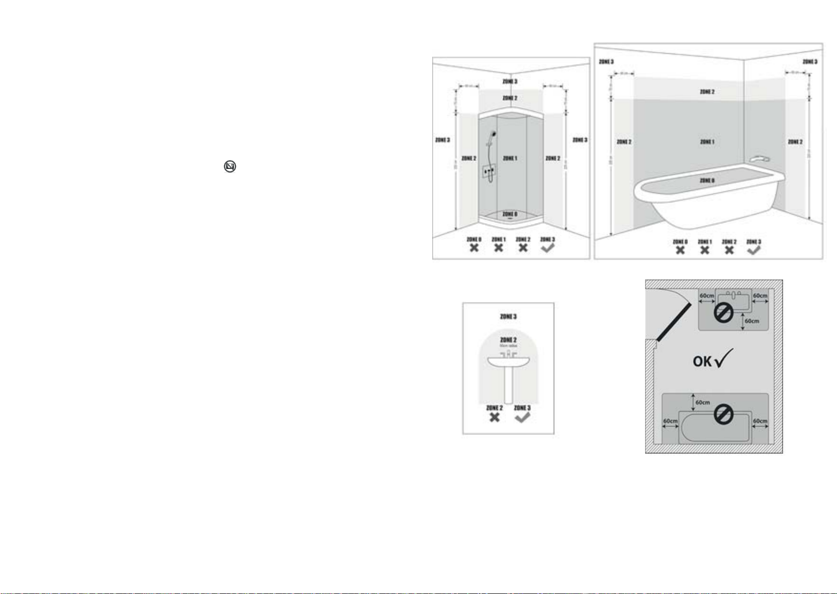
• The appliance is suitable for use in the bathroom only in zone 3 and must
always be prevented from direct contact with water.
• If any uids or foreign object may become lodged within the panel,
disconnect it from power and have it checked by a service technician.
• The appliance has an earthed power cord which is to be used with 230V
power outlets. In case the power cord or the appliance itself becomes
damaged, it should be repaired by a professional.
• Do not attempt to disassemble the appliance. It contains many parts and
the warranty will become void. Dis-assembly and/ or reassembly should
not be done outside the factory or a specialized service center.
• To avoid electrocution, remove the power cord if a defect has been
identied, or if the panel is to be moved.
• Protection against overheating and re hazard: The panel can at instances
reach a surface temperature of 125°C. DO NOT cover the panel at any
time nor put easily ammable fabrics or other objects directly in front
of the panel.
• Before drilling into the wall for installation, rst check that the area is free
of electrical wires, gas or water pipes or any other obstacles that could
be damaged.
• First time use: verify that all of the packaging materials have been
removed. In case you notice an odor due to panel operation, switch it
o immediately, then identify and remove the source. In case the smell
persists, contact your point of sale.
• Do not install the heating panel directly over (covering) its electrical
socket.
• Install the panel where its plug will be easily accessible.
• Do not in any case use the heating panel if its glass surface is cracked or
otherwise damaged.
• Infrared heating panels are not toys and children should be clearly
instructed and supervised by adults.
• FIRST panels are designed to withstand moderate power drops/surges at
voltages between 220V and 250V. Verify before use that the panel you are
installing is suited for your regional supply voltage. When this would not
be the case, do not plug in the appliance and contact your supplier. In
case the panel is plugged into an outlet with the wrong voltage, or when
power surges are out of the range as described before, the warranty will
NOT cover these damages.
• Do not attempt to clean the heating panel while it is connected to the
electrical power supply. First unplug the power cord, and then the
appliance may be cleaned with a soft, dry cloth.
• Battery Disposal: Thermostat batteries intended for disposal are
considered hazardous waste and may not be included with municipal
waste. Please follow your local laws and procedures for proper disposal
of these materials.
• DO NOT COVER: To prevent the panel from overheating, do not
cover or conceal it with textiles, items of clothing, or other objects of
any type.
• WARNING: Be sure that the heating panel is installed above its electrical
power outlet.
• WARNING: The heating panel may not used if its glass cover is damaged.
Immediately turn o the heating panel if damage to the the glass occurs.
• The heating panel is not intended for use by persons (including children)
with reduced physical, sensory or mental capabilities. Those lacking
experience concerning the use of heating panels should be given
instruction by a person aware of their safe use.
• Children should be supervised not to play with heating panels. They are
NOT toys and children should be clearly instructed and supervised by
adults.
• The appliance is suitable for use in bathrooms at ZONE 3 or further from
water sources. The illustration below is for reference. In all cases, be sure
that the power outlets in your bathroom are equipped with an RCD
(Residual Current Device) to protect the electrical circuit.
Safety notes

Rev.: 0
This manual suits for next models
3
Table of contents
Other First Heating Heater manuals


 20 owner's manual")


