Iridium SHOUT ns Operating and maintenance instructions

GENERAL DESCRIPTION OF MODEL SHOUT ns
Revision B
July 12, 2019
451-01001.B
Copyright © 2019 by NAL Research Corporation
9385 Discovery Boulevard, Suite 300
Manassas, Virginia 20109 USA
Phone: 703-392-1136 x203
E-mail: contact@nalresearch.com

NAL Research Corporation (451-01001.B) 2
LEGAL DISCLAIMER AND CONDITIONS OF USE
This document contains information for the NAL Research Corporation SHOUT ns Tracker
and accompanying accessories (“Product”) is provided “as is.” Reasonable effort has been
made to make the information in this document reliable and consistent with specifications,
test measurements and other information. However, NAL Research Corporation and its
affiliated companies, directors, officers, employees, agents, trustees or consultants (“NAL
Research”) assume no responsibility for any typographical, technical, content or other
inaccuracies in this document. NAL Research reserves the right in its sole discretion and
without notice to you to change Product specifications and materials and/or revise this
document or withdraw it at any time. User assumes the full risk of using the Product
specifications and any other information provided.
NAL Research makes no representations, guarantees, conditions or warranties, either
express or implied, including without limitation, any implied representations, guarantees,
conditions or warranties of merchantability and fitness for a particular purpose, non-
infringement, satisfactory quality, non-interference, accuracy of informational content, or
arising from a course of dealing, law, usage, or trade practice, use, or related to the
performance or nonperformance of any products, accessories, facilities or services or
information except as expressly stated in this guide and/or the Product and/or satellite service
documentation. Any other standards of performance, guarantees, conditions and warranties
are hereby expressly excluded and disclaimed to the fullest extent permitted by the law. This
disclaimer and exclusion shall apply even if the express limited warranty contained in this
guide or such documentation fails of its essential purpose.
In no event shall NAL Research be liable, whether in contract or tort or any other legal
theory, including without limitation strict liability, gross negligence or negligence, for any
damages in excess of the purchase price of the Product, including any direct, indirect,
incidental, special or consequential damages of any kind, or loss of revenue or profits, loss of
business, loss of privacy, loss of use, loss of time or inconvenience, loss of information or
data, software or applications or other financial loss caused by the Product (including
hardware, software and/or firmware) and/or the Iridium satellite services, or arising out of or
in connection with the ability or inability to use the Product (including hardware, software
and/or firmware) and/or the Iridium satellite services to the fullest extent these damages
may be disclaimed by law and whether advised of the possibilities of such damages. NAL
Research is not liable for any claim made by a third party or made by you for a third party.
NAL Research Corporation (451-01001.B) 3
REVISION HISTORY
Revision
Date
Description
Author
A
2/5/19
Initial version
A. Schiltz
B
7/12/19
Editorial and format updates. Added
Reference Documents and sections for
Quick Start User Guide, SHOUT Android
App, and Nal Vue Management Tool.
A. Schiltz
REFERENCE DOCUMENTS
The latest revision of these documents are available from the NAL Research website at
(http://www.nalresearch.com/Downloads.html).
Reference
Title
Revision / Date
[1]
AT Commands for Model SHOUT ns
Revision 1.0.5,
23 March 2018
[2]
NAL GPS Report Version 6 Format
Revision 3,
26 September 2018
[3]
PECOS Message Definition Specification, 200907-
001
Version 1.7
July 29, 2009
[4]
SHOUT App User Guide
[5]
NAL Vue Users Guide

NAL Research Corporation (451-01001.B) 4
TABLE OF CONTENTS
LEGAL DISCLAIMER AND CONDITIONS OF USE.................................................. 2
REVISION HISTORY........................................................................................ 3
REFERENCE DOCUMENTS................................................................................ 3
TABLE OF CONTENTS ..................................................................................... 4
GLOSSARY .................................................................................................... 7
1.0 PURPOSE ........................................................................................... 9
2.0 GENERAL SPECIFICATIONS ................................................................ 11
2.1 Mechanical Specifications .............................................................................. 11
2.2 Iridium RF Specifications............................................................................... 12
2.3 GPS Specifications ....................................................................................... 12
2.4 Bluetooth RF Specifications ...........................................................................12
2.5 Electrical Specifications................................................................................. 13
2.6 Environmental Specifications ......................................................................... 13
2.7 Data I/O Specifications ................................................................................. 13
2.8 Related Hardware ........................................................................................13
3.0 USER INTERFACES............................................................................ 14
3.1 Power Button...............................................................................................14
3.2 Bluetooth Button..........................................................................................14
3.3 Emergency / 911 Mode Activation ..................................................................14
3.4 Status LEDs ................................................................................................14
3.5 USB Port ..................................................................................................... 16
3.5.1 USB Data ................................................................................................. 17
3.5.2 DC Power Inputs ....................................................................................... 17
3.6 Bluetooth .................................................................................................... 17
4.0 QUICK START USER GUIDE ................................................................ 19
4.1 Device Preparation .......................................................................................19
4.2 Device Start-up ...........................................................................................19
4.3 Device Charging .......................................................................................... 19
4.4 Device GPS reception and Iridium Registration ................................................20
4.5 Configuring the SHOUT ns with the SatTerm Application ...................................20
4.6 Device Bluetooth pairing with the SHOUT Android App...................................... 21
4.7 AT Command Mode ......................................................................................22
5.0 IMPORTANT FEATURES ...................................................................... 23
5.1 Communication Links ................................................................................... 23
5.2 Modes of Operation ......................................................................................23
5.2.1 Command Mode........................................................................................ 23
5.2.2 Tracking Mode ..........................................................................................23

NAL Research Corporation (451-01001.B) 5
5.3 Call-Outs and Power-Up Delay .......................................................................25
5.4 Geofencing..................................................................................................25
5.5 Motion Detection..........................................................................................25
5.6 Encryption ..................................................................................................26
5.7 Remote Updates .......................................................................................... 26
6.0 CONFIGURING THE SHOUT NS ........................................................... 27
6.1 Profile Descriptions ......................................................................................27
6.1.1 General Profiles ........................................................................................ 27
6.1.2 Tracking Profiles .......................................................................................27
6.1.3 Additional Setup Parameters ...................................................................... 28
6.2 Using SatTerm............................................................................................. 28
6.2.1 Connecting SatTerm to the SHOUT ns .........................................................28
6.2.2 Configure Window .....................................................................................31
6.2.3 Geofencing............................................................................................... 51
6.2.4 Call Out ...................................................................................................54
7.0 NAL SHOUT ANDROID APP OVERVIEW................................................. 56
7.1 Pairing the SHOUT ns with a Smartphone........................................................56
7.2 SHOUT App Screen Overview ........................................................................ 56
7.2.1 Title Bar................................................................................................... 56
7.2.2 Status Bar................................................................................................ 57
7.2.3 Menu Functional Area ................................................................................59
7.2.4 Bottom Dock ............................................................................................ 59
7.3 Texting Menu .............................................................................................. 59
7.4 Tracking Menu ............................................................................................. 59
7.5 Utilities Menu ..............................................................................................60
7.6 Settings Menu .............................................................................................61
8.0 SHOUT NS USE WITH THE NAL VUE MANAGEMENT TOOL....................... 62
8.1 Overview .................................................................................................... 62
8.2 NAL Vue User Interface................................................................................. 62
8.2.1 Six Core Tabs ........................................................................................... 62
8.2.2 Assets Tab ...............................................................................................63
8.2.3 Alerts ...................................................................................................... 65
8.2.4 Reports.................................................................................................... 66
8.2.5 Settings and Preferences ...........................................................................67
8.2.6 Users ......................................................................................................69
9.0 TECHNICAL SUPPORT ........................................................................ 70
APPENDIX A: STANDARDS COMPLIANCE......................................................... 71
APPENDIX B: EXPORT COMPLIANCE INFORMATION .......................................... 72
APPENDIX C: DESCRIPTION OF THE IRIDIUM NETWORK................................... 73
C.1 Description of the Iridium Network .................................................................... 73
C.2 Description of the Iridium Network Data Capabilities............................................74
C.2.1 Dial-Up Data Service ...................................................................................74
C.2.2 Direct Internet Connection ...........................................................................76

NAL Research Corporation (451-01001.B) 6
C.2.3 Router-based Unrestricted Digital Internetworking Connectivity Solution (RUDICS)
.........................................................................................................................77
C.2.4 Short-Burst Data (SBD) ...............................................................................77
C.2.5 Short Messaging Service (SMS) ....................................................................77
C.3 Iridium Geo-Location .......................................................................................78
MECHANICAL DRAWING................................................................................ 79

NAL Research Corporation (451-01001.B) 7
GLOSSARY
AES Advanced Encryption Standard
BIS Bureau of Industry and Security
CE Conformité Européen
CEP Circular Error Probability
CFR Code of Federal Regulations
DGPS Differential Global Positioning System
DoD Department of Defense
DoD EMSS DoD Enhanced Mobile Satellite Services
DTE Data Terminal Equipment
DSN Defense Switch Network
EAR Export Administration Regulations
EMI Electromagnetic Interference
ETSI European Telecommunications Standards Institute
FCC Federal Communications Commission
FDMA Frequency Division Multiple Access
GND Ground
GPS Global Positioning System
GSM Global System for Mobile Communication (Groupe Spécial Mobile)
GUI Graphical User Interface
ID Static Identifier
IMEI International Mobile Equipment Identification
ISU Iridium Subscriber Units
LED Light Emitting Diode
Li-Ion Lithium Ion
LNA Low Noise Amplifier
LP Low Power
NOC Network Operation Center
OFAC Office of Foreign Asset Controls
PMS PECOS Message Structure
PSTN Public Switch Telephone Network
PWR Power
RHCP Right Hand Circular Polarization
RUDICS Router-Based Unrestricted Digital Internetworking Connectivity Solution
SatTerm Satellite Terminal Emulator Software

NAL Research Corporation (451-01001.B) 8
SBD Short Burst Data
SMA Sub-Miniature Version A
SMS Short Message Service
TDD Time Division Duplex
TDMA Time Division Multiple Access
VSWR Voltage Standing Wave Ratio

NAL Research Corporation (451-01001.B) 9
1.0 PURPOSE
The SHOUT ns is a pocket-sized, low-cost, low-power, Iridium satellite network tracking
device. It is designed to relay, via the Iridium satellite network, GPS location data and other
critical data such as emergency messages, geofence data, and callouts from the device and
text messages from the NAL SHOUT smart phone app. It has a rugged plastic housing with
embedded Iridium, GPS, and Bluetooth antennas. This device can easily be carried by a person
or attached to high value, un-tethered or non-powered assets.
The SHOUT ns comprises an Iridium 9603 transceiver module, a built-in 72-channel u-
blox GPS receiver, and low power micro-controllers. The SHOUT ns can send short-burst data
(SBD) messages over the Iridium satellite network. The SHOUT ns can transmit messages in
NAL Research’s defined report formats compatible with models 9602-LP, 9602-AB, the A3LA
series modems, and SHOUT series tracking devices. The SHOUT ns can also transmit in PECOS
Message Structure (PMS). The PMS complies with the Blue Force Tracking Data Format
Specification as defined in the document PECOS Message Definition Specification, 200907-
001 Version 1.7 [3]. When requested by an authorized user, NAL Research can enable the
SHOUT ns to utilize the DoD DISA EMSS (Enhanced Mobile Satellite Services) Gateway when
sending over the Iridium satellite network.
IMPORTANT: EMSS-enabled SHOUT ns must first be provisioned (signed up
for airtime) with EMSS SBD Service before testing or field use. Accessing the
DoD EMSS Gateway is not authorized until the SHOUT ns is provisioned.
Unauthorized attempts to access the DoD EMSS Gateway will result in
immediate disabling of the offending device, which must then be returned to
NAL Research for repair. See https://sbd.pac.disa.mil/ for more information
regarding EMSS service provisioning.
The SHOUT ns is designed with ultra-low power consumption electronics. It is capable of
delivering uninterrupted service for up to 20 days at one report per hour. Power consumption
can be further reduced by using the device’s built-in motion sensor and/or geofencing features
to reduce reporting frequency when a platform is not in motion or is outside an area of
interest. In addition to normal tracking, the SHOUT ns also has a real-time clock allowing
power-up delay as well as scheduled daily Call Outs.
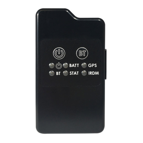
Externally, the SHOUT ns has two buttons and six LEDs to provide the user control and
status of the device. The six LEDs provide the status of power state, battery charging status,
GPS fix, Bluetooth connection status, report transmission status, and Iridium connection

NAL Research Corporation (451-01001.B) 10
status to the user. Using the Power and Bluetooth buttons, the user can activate an
Emergency/911 Mode to send an emergency message with an increased reporting rate. An
available micro USB port can be used to communicate with a laptop for configuration or data
collection.
The SHOUT ns also has an associated Android app for use with a Bluetooth enabled
smartphone or tablet to provide the same functionality as other NAL SHOUT devices with
displays. Functionality provided includes text messaging, managing tracking parameters such
as reporting rate, reporting format, and geofencing, diagnostic utilities, and configuring the
SHOUT ns. This application is available from NAL Research via the Google Play App Store.
More details are provided in Section 7.0 NAL SHOUT Android App Overview.

NAL Research Corporation (451-01001.B) 11
2.0 GENERAL SPECIFICATIONS
2.1 Mechanical Specifications
Dimensions: 3.30 x 1.80 x 0.74 inches (84 x 46 x 19 mm) (see drawing
in Appendix)
Weight: 3.0 oz. (85 g)
Enclosure: Hard ABS plastic
Interface Connector: USB Micro B receptacle
Antennas: Embedded Iridium, GPS, and Bluetooth antennas
ON/OFF button: Dome push button
Bluetooth Switch: Dome push button
Status LED Displays: Power, Battery, GPS, Bluetooth, message sent status,
Iridium
Figure 1. SHOUT ns Buttons and Indicators.
Figure 2. SHOUT ns Accessories.
USB-to-micro USB Cable
AC Wall Adapter
Manuals and Software

NAL Research Corporation (451-01001.B) 12
2.2 Iridium RF Specifications
Operating Frequency: 1616.0 to 1626.5 MHz
Duplexing Method: TDD
Multiplexing Method: TDMA/FDMA
RF TX output power (Average): 1.6 W
Rx Sensitivity at 50(Typ): –117 dBm
Link Margin –Downlink: 13 dB
Link Margin –Uplink: 7 dB
2.3 GPS Specifications
Type of GPS Receiver: u-Blox MAX-8MQ
Receiver Type: 72-Channel GPS L1 C/A, SBAS, QZSS, GLONASS
Update Rate: 4 Hz
Accuracy: Position 8.2 feet (2.5 meters) CEP
Position SBAS 6.6 feet (2.0 meters) CEP
Acquisition (typical): Hot starts 1 second
Aided starts 2 seconds
Cold starts 29 seconds
Sensitivity: Tracking 166 dBm
Reacquisition 160 dBm
Cold starts 148 dBm
Operational Limits: Altitude 164,000 feet (50,000 meters)
Velocity 1,640 feet/sec (500 m/s)
Dynamics ≤ 4g
As long as power is provided to the SHOUT ns, the GPS receiver will provide Real-Time
clock functionality and will store ephemeris data in its memory before powering down (sleep
between reports). The ephemeris data are valid up to two hours and can be used in future
startup to improve time-to-first-fix.
2.4 Bluetooth RF Specifications
Operating Frequency: 2.4 GHz
Protocol: Bluetooth Low Energy v4.0
Data Rate: 2.178 Mbps
Power Output: +10 dBm
Sensitivity: -93 dBm

NAL Research Corporation (451-01001.B) 13
2.5 Electrical Specifications
Voltage Input Range: +3.0V to +4.2V (+3.7V DC nominal)
Power Input Type: Internal CR123 650 mA-Hr rechargeable battery
or external DC power via the USB port
USB Input Power: +4.3V to +5.5VDC, up to 1A
Current in Between Reports (sleep): Less than 110A @ +3.7V
NOTE: The average current drawn during transmission may vary depending on
the field-of-view between the SHOUT ns antenna and the Iridium satellite.
2.6 Environmental Specifications
Design Operating Temperature Range: –4oF to +140oF (–20oC to +60oC)
Charging Temperature Range: +32oF to +113oF (–0oC to +45oC)
Ingress Protection: IP67
Operating Humidity: ≤ 75% RH
2.7 Data I/O Specifications
Short-Burst Data Mobile-Originated: 340 bytes per message (Iridium)
Short-Burst Data Mobile-Terminated: 270 bytes per message (Iridium)
Multi-Interface connector: USB
Software Interface: AT commands via USB
2.8 Related Hardware
AC Power Adapter: LA-3098 (100-240VAC, 47-60Hz input)
12V Car Adapter: LA-7021 (12VDC car battery input)

NAL Research Corporation (451-01001.B) 14
3.0 USER INTERFACES
3.1 Power Button
The SHOUT ns has a single power ON/OFF button. The SHOUT ns can be turned off and
on again by momentarily holding down the power button for two seconds and releasing it. If
the device is sleeping, briefly pressing the Power button will turn the SHOUT ns on for 10
seconds. The ON/OFF button is also used with the Bluetooth button for Emergency Mode
activation. See Section 3.3 Emergency / 911 Mode Activation for details.
3.2 Bluetooth Button
The SHOUT ns has a single Bluetooth (“BT”) button. When this button is pressed for two
seconds, the Bluetooth link is activated. When the Bluetooth button is pressed again for two
seconds, the Bluetooth link is de-activated. If the device is sleeping, pressing the Bluetooth
button will turn the SHOUT ns on for 2 minutes. This extended duration as compared to the
power button is to give sufficient time to connect and pair with the Bluetooth interface. Refer
to Section 3.6 Bluetooth for details on use of the Bluetooth interface. The Bluetooth button
is also used with the power button for Emergency Mode activation. See Section 3.3
Emergency / 911 Mode Activation for details.
3.3 Emergency / 911 Mode Activation
The SHOUT ns has an Emergency / 911 mode which will immediately send a location
report with the Emergency bit set and thereafter send location reports at a rate configured in
the Emergency Report Rate parameter until the Emergency / 911 mode is canceled. All text
messages sent when the Emergency / 911 mode is active will also have the Emergency flag
set. In order to activate the emergency / 911 mode feature on the SHOUT ns, a four (4)
button press sequence must be initiated. This sequence involves alternating between the
Power Button (first) and Bluetooth Button for a total of two (2) times each. This action will
result in all six (6) LEDs blinking at the same time once per second until the device is turned
off. This sequence can be activated with the SHOUT ns powered on or off. Emergency is
deactivated when the SHOUT ns is powered off and will not resume emergency operation until
it is the emergency mode is activated again.
3.4 Status LEDs
The SHOUT ns has six status LEDs, as shown in Figure 3, which include: power ( ),
Bluetooth state (BT), GPS fix (GPS), Iridium signal (IRDM), battery level (BATT), and
transmission status (STAT). They offer users a quick visual check to ensure proper operations.

NAL Research Corporation (451-01001.B) 15
Each LED can be enabled and disabled through a setting in the general configuration profile
(^LEDS) (see Section 6.2.2.1 General Profile Settings). Table 1 below describes the function
of each LED.
Figure 3. Control Buttons and Status LEDs on the SHOUT ns front face.
LABEL
NAME
LED OFF
LED BLINKING
LED SOLID
Power
Device is off
Once every 5 sec: Device is on
and sleeping in Normal Mode
Once every 2.5 sec: Device is
on and sleeping in Emergency
Mode
Device is on and awake
BATT
Battery
During Operation:
Charge Required
During Operation:
Charge under 80%;
1.25 sec On, 0.25 sec Off
Charge under 20%;
0.125 sec On, 1.00 sec Off
While Charging:
Charge in Progress;
1.25 sec On, 0.25 Off
During Operation:
Charge over 80%
While Charging
Charge Complete
GPS
GPS
GPS Off or time only
2-D fix or dead reckoning
3-D fix
BT
Bluetooth
Bluetooth off
1 sec: Bluetooth on and not
connected / pairing
Bluetooth on and
connected
STAT
Status
No successful report
transmission
1 sec: Last report transmission
failed
Last report
transmission succeeded
IRDM
Iridium
Off or has no signal
Has 1 - 2 bars of signal
Has 3 - 5 bars of signal
Table 1. Description of LED states.

NAL Research Corporation (451-01001.B) 16
Special Functions - The SHOUT ns features two (2) special LED patterns that indicate
the following:
Emergency Mode Active - All six (6) LEDs blink simultaneously in a 0.5 sec on
and 0.5 sec off pattern for as long as the emergency mode is active and the
device is awake. When the device is asleep, the 6 LED pattern stops but the
power LED blink rate changes from once every 5 seconds for Normal mode to
once every 2.5 seconds for Emergency mode.
Upon Charger Connection –When power is on*, the Battery, GPS, Iridium,
and Status LEDs blink in clockwise sequence for 3 seconds when power is
applied.
After a Special Function has ended, the LEDs revert to their standard operating state.
* NOTE: There are no LED indicators while the SHOUT ns is powered off
and while plugged in and charging. To verify charge status, the SHOUT
ns must be turned on.
3.5 USB Port
Figure 4. Position of USB Connector.
The USB connector on model SHOUT ns is a USB micro B receptacle located on the right
of the chassis as shown in Figure 4. This connector has a rubber O-ring sealed cover required
to achieve the IP67 rating of the device. The USB connector pin assignments are detailed
below in Table 2.

NAL Research Corporation (451-01001.B) 17
PIN #
SIGNAL
DESCRIPTION
INTERFACE
IN/OUT
1
VBUS
USB VBUS
USB
I
2
USBD-
USB data
USB
IO
3
USBD+
USB data
USB
IO
4
ID
USB OTG ID
USB
IO
5
GND
Ground
USB
--
Table 2. Pin assignments for the SHOUT ns USB connector
IMPORTANT: Ensure proper closure of the rubber sealing cover shown in Figure 4
before exposing the SHOUT ns to water.
3.5.1 USB Data
The SHOUT ns communicates to computer equipment using the USB Micro B port located
on the right side of the chassis (see Figure 4). The USB connection allows configuration of
and data collection from the SHOUT ns using NAL Research’s defined AT commands and NAL’s
SatTerm console window. These AT commands can be found in the manual “AT Commands
for Model SHOUT ns” [1] and also see Section 5.2 Modes of Operation. NAL Research
recommends the use of SatTerm graphical user interface (GUI) software to configure the
SHOUT ns instead of trying to memorize various AT commands. The latest version of this
software can be downloaded on the NAL Research webpage
(http://www.nalresearch.com/Downloads.html).
3.5.2 DC Power Inputs
The device can be powered from and recharge the internal battery through the USB Micro
B port. A USB 1.0 host (100 mA) can charge the battery within 8 hours and a USB 2.0 host
(500 mA) can charge the battery within 2 hours.
3.6 Bluetooth
The SHOUT ns utilizes a Bluetooth Low Energy (BLE) transceiver to provide a secondary
command interface to the micro USB port. This interface can be used to interface with
SatTerm and the NAL SHOUT Android app.
To pair a device with the SHOUT ns, an initial connection to the USB interface is required.
During the pairing process utilizing SatTerm, the command AT^BTPASS is used to enter the
passkey. Devices without a display such as the SHOUT ns will require passkey entry on the
master device. If this occurs, the SHOUT ns will provide the passkey to be entered. Refer to
the document "AT Commands for Model SHOUT ns" [1] for additional details. The SatTerm

NAL Research Corporation (451-01001.B) 18
application is described in more detail in Section 6.2 Using SatTerm. The NAL SHOUT Android
app is described in more detail in Section 7.0 NAL SHOUT Android App Overview.
The Bluetooth interface has a 10-minute idle timer which will turn off the Bluetooth
interface when there is no data transfer or it is disconnected for 10 minutes. To keep the
interface alive, an AT command such as just “AT”(the SHOUT ns will simply respond with
“OK”) should be sent periodically.

NAL Research Corporation (451-01001.B) 19
4.0 QUICK START USER GUIDE
This quick start user guide provides an overview for the user to receive the SHOUT ns and
transition it to operational use.
4.1 Device Preparation
Prior to use of the SHOUT ns, airtime must first be purchased from NAL Research or from
any Iridium certified airtime reseller. The SHOUT ns IMEI number must be registered by an
airtime reseller to “point” to a Network Operations Center (NOC) server. This section covers
how the user can quickly set up the SHOUT ns as a tracking device.
Remove the SHOUT ns, the wall charger and the USB cable from the packaging. Remove
the SHOUT ns USB port cover (see Figure 4) and connect the USB cable USB micro port to
the SHOUT ns. Connect the USB-A connector to the wall charger.
4.2 Device Start-up
Activate the SHOUT ns by pressing the power button ( ) for two seconds until the Power
LED ( ) illuminates. The Power LED should remain steadily illuminated. The Battery LED
should then start blinking in a 1.25 sec On and 0.25 sec Off pattern to indicate the battery
requires charging. If the battery is blinking in a 0.125 sec On and 1.0 sec Off pattern, this
indicates the battery is at less than 20% charge and will take longer to fully charge.
NOTE: If the device is not used for 10 minutes, the SHOUT ns will enter sleep
mode and the Power LED will change to blinking once every 5 seconds to
indicate it is asleep. The SHOUT ns can be removed from the sleep mode by
pressing the Power button for two seconds.
Before charging the unit, test the Emergency / 911 Mode activation feature with the
following button press combination; Power, Bluetooth, Power, Bluetooth. The SHOUT ns
should enter the Emergency / 911 Activation mode and all six LEDs should start flashing once
per second to indicate this mode is active. To cancel this mode, hold the power button for
two seconds to shut the device off. Hold the power button again for two seconds to power
the device back on. Again confirm the Power LED should remain steadily illuminated and the
Battery LED begins to blink as described above.
4.3 Device Charging
The SHOUT ns is shipped with a partially charged battery. Before use, the SHOUT ns
should be charged for one hour.**

NAL Research Corporation (451-01001.B) 20
** NOTE: Upon battery depletion, the SHOUT ns should reach full charge within
2 hours of being continuously plugged in.
Plug the wall charger into a 115V AC power source. Confirm that when the wall charger
is plugged in and power is applied to the SHOUT ns USB port, the Battery, GPS, Iridium, and
Status LEDs blink in clockwise sequence for 3 seconds. Let the SHOUT ns charge for several
hours or until the BATT LED changes to steady illumination.
4.4 Device GPS reception and Iridium Registration
After charging the SHOUT ns, the device is ready to use. Hold the Power Button for 2
seconds. The Power LED and Battery LED will light up and the device will begin functioning.
Ensure the top of the SHOUT ns has a clear view of the sky. The standard LED sequence
during a successful report is as follows:
a) The GPS LED lights first when a signal has been acquired.
b) The Iridium (IRDM) LED will begin lighting when an Iridium signal has been
acquired, either solid or blinking based on signal strength.
c) The Status (STAT) LED will begin lighting when a report has been transmitted.
Once this has been accomplished, all LEDs will turn off and the power LED will blink
intermittently, indicating the device is in sleep mode awaiting the next report transmission.
4.5 Configuring the SHOUT ns with the SatTerm Application
The SHOUT ns is shipped with default settings below:
-Report Rate ................................................5 Minutes
-Emergency Report Rate ...............................5 Minutes
-Transmit Report Without GPS Fix ..................Yes
-Message Format..........................................NAL Message Format
If these default settings are not what the user desires, the SHOUT ns supports a micro
USB connection to a computer with SatTerm software (or any terminal emulator software) to
configure its operating profile using NAL Research’s defined AT commands. These AT
commands can be found in the manual “AT Commands for Model SHOUT ns” [1].
The required hardware and software for the configuration of the SHOUT ns include:
1. A desktop or laptop computer (not provided).
2. A USB-A to USB micro B cable (provided with the SHOUT ns).
3. A USB AC Adapter (provided with the SHOUT ns).
Table of contents
Other Iridium GPS manuals

Iridium
Iridium Blue Sky Network HawkEye User manual

Iridium
Iridium SHOUT nano User manual

Iridium
Iridium GO! 9560 User manual

Iridium
Iridium EXTREME User manual

Iridium
Iridium YB3 Installation guide

Iridium
Iridium NAL SHOUT ns User manual

Iridium
Iridium TT36013G User manual

Iridium
Iridium YB3 Rental Tracker Installation guide