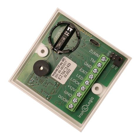
Iron logic Z-5R Relay Wiegand User manual

Page 1
Z-5R Relay Wiegand www.ironlogic.me
Z-5R Relay Wiegand / Z-5R Relay Wiegand
Case Controllers
User Manual
1. OVERVIEW
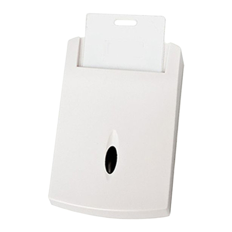
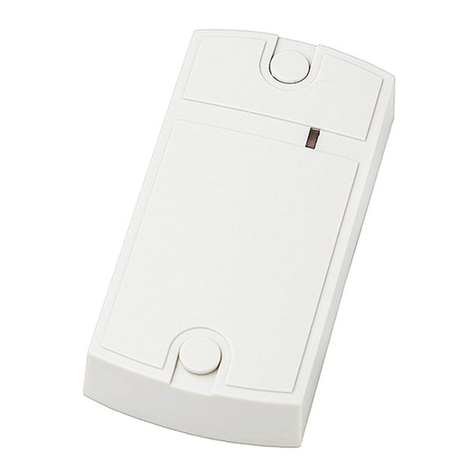
Controllers Z-5R Relay Wiegand or Z-5R Relay Wiegand Case (modification with plastic case) are
used in Access Control Systems (ACS) as standalone controllers with output power relay that
operate external devices. As input devices a Dallas Touch Memory contactor (reader for DS1990A
keys), or a contactless proximity card reader emulating iButton (Dallas Touch Memory) or Wiegand
(26-42 bits) protocol can be connected.
The following equipment can be connected to a Z-5R Relay Wiegand controller:
- External proximity card reader, transmitting information via iButton protocol, or Dallas Touch
Memory contactor.
- Relay controlled lock;
- Lock release button (normally unlocked);
- External LED;
- External buzzer;
- Door sensor.
2. SPECIFICATIONS
- External reader connection protocol ..............iButton (Dallas Touch Memory), Wiegand (26-42 bits)
- Maximum number of keys.........................................................................................................1364
- DS1996L key support .................................................................................................................Yes
- Audiovisual indication..............................................................................................LED and buzzer
-External control for LED and buzzer ............................................................................................Yes
- Output for lock...........................................................................................................................relay
- Switching current (24В DC/120В АС), А..........................................................................................3
- Jumper for initial relay state selection.......................................................................................on/off
- Lock release duration timer................................................................0…220 s (factory default is 3
s)
- Power supply operating voltage, V............................................................................................8 - 18
- Maximum operating current....................................................................................................45 mA
- Case dimensions, mm ....................................................................................................65 x 65 x 20
- PCB dimensions, mm .....................................................................................................46 x 35 x 15
- Case material (for Z-5R Relay Wiegand Case)................................................................ABS plastic
A twisted pair cable (e.g. UTP CAT5) should be used to connect the reader or key probe to the
controller, to avoid interference. When connected via iButton (Dallas Touch Memory) protocol, one
wire of a twisted pair is used to connect GND terminals of the reader and the controller. Second wire
of this twisted pair is used for signal transmission, and connects the reader output with the D0
terminal on the controller (see Fig. 4 and 5).
The power to the reader can be delivered using a single wire. If unused wires remain in the cable,
connect them between GND terminals on the reader and the controller.

Page 2
Z-5R Relay Wiegand www.ironlogic.me
Table 1. Terminals designation.
No.
Terminal
Designation
1
D1
Wiegand interface DATA 1 data bus for reader. Circuiting this terminal
to GND activates the iButton inquiry at terminal D0.
2
D0
Connecting a reader or contactor via iButton protocol, or Wiegand
interface DATA 0 data bus for the reader.
3
GND
Signal ground, to connect “common” wires of an external reader, a
contactor, a door sensor or a door release button.
4
EXIT
Door release button. Short-circuit to GND causes door release. A twisted
pair (TP) connection recommended.
5
LED
External LED. Output current is limited to 20 mA, thus an LED can be
connected without resistors. LED's positive terminal is connected here,
and LED's negative one –to GND terminal.
6
SND
External control of the reader's audio signal or for connecting the negative
contact of an external sound source (current consumption up to 1A).
7
+12V
Connecting the positive terminal of a power supply. 9 – 24 V.
8
GND
Power ground, to connect the negative terminal of a power supply.
9
DOOR
Door sensor connects here.
Figure 1. Controller case dimensions Figure 2. Controller PCB layout
3. OPERATING FEATURES
1. The Controller can work both with DS1990A keys, as well as contactless cards or tokens of various
standards. To work with DS1990A keys, connect a contactor to controller. To work with cards,
connect a reader supporting the corresponding card protocol (EM-Marine, Mifare etc.) Considering
that contactless systems have almost fully superseded contact ones in use, hereinafter we will
describe the controller operation on example of a Matrix II reader connected via iButton (Dallas
Touch Memory), which is almost 100% similar to operation with a contactor.

Page 3
Z-5R Relay Wiegand www.ironlogic.me
2. ACS actions are determined from presence or absence of the card ID and card status in controller
memory. “Card ID” is also often called a “key”, so further in this document we shall consider “card”
and “key” terms equal (e.g. we can say “touch with a card” or “touch with a key” with same effect). The
full list of cards (keys) with their status, stored in controller's memory, is called ACS database.
3.To work with Z-5R Relay Wiegand controller, each new proximity card should be assigned a
“status” (access rights). Status is determined during the card programming, on first approach of the
card to the reader connected to the controller. Therefore, to change a card's status, delete it from the
controller memory, then add it again with the correct status. Please note that to delete a Master card,
the entire controller memory (ACS Database) must be erased or rewritten.
- Card status can be as follows:
- Master card is used for Z-5R Relay Wiegand programming only; never is used for access.
- Normal (Access) card is used for passing through access point (except when in Blocking Mode).
- Blocking card is used for both passing through access point (including when in Blocking Mode), and
enabling/disabling the Blocking Mode.
Note: The Blocking cards open the lock when the card is taken away from the reader.
4. A brand new Z-5R Relay Wiegand controller has empty memory. To operate a Z-5R Relay
Wiegand, first store a Master card information into its memory. This Master card will be used for
device programming. Later we will describe how to write a Master card.
ACS Operating Modes with Z-5R Relay Wiegand:
- Standard Mode access granted for both Normal and Blocking cards.
- Blocking Mode access granted only for Blocking cards, but not for Normal cards. Convenient when
access needs to be temporarily restricted to certain group of people only.
- Accept Mode access is granted for existing Normal and Blocking cards, as well as any new cards.
All new cards used in this mode will be stored into controller's memory, and assigned Normal card
status. Thus after certain time spent operating in this mode, the controller will have built a new ACS
database.
- Trigger Mode emulates a simple lock operation logic. Each card touch leads to a steady change of
state of the controller relay. Thus, when the relay is turned on, one short beep is issued, when turned
off, four short beeps. This mode normally is used with electromagnetic locks, but other devices can
also be used with it. However, please bear in mind that locking devices not designed for extended
operating time, such as electromechanical locks, can fail when operating in this mode.
- Relay mode - in contrast to the Trigger Mode, in this mode the “relay on” state is saved only when
the card is held in the reader field. Typically, readers for such applications are equipped with a special
pocket or other card-holding device. After removing the card relay goes into the “off” state after the
set time for opening the lock.
Attention! To work in “Relay mode”, the reader must be connected via iButton protocol.
Audio-visual indication on the controller:
When the card touches the reader connected to the controller, it is either:
- Present in Z-5R Relay Wiegand controller database. The green LED blinks, the buzzer sounds,
the lock is released for specified lock release duration (or until door sensor is triggered).
- Absent from Z-5R Relay Wiegand controller database. The green LED blinks twice, and two
buzzer beeps are emitted.

Page 4
Z-5R Relay Wiegand www.ironlogic.me
4. PROGRAMMING
Important: Before programming the controller, please ensure that a contactor or reader is
connected.
When describing programming procedures, we will use the term “card touch to the reader”. It means
approaching the reader connected to this controller with a card, to a distance that will ensure reliable
card ID acquisition (less than 2 cm).
Programming the controller depends on the protocol to which the external reader is connected. Only
the master card is used for programming.
External reader is connected via iButton protocol. The special feature of this protocol is that it has
a signal on the reader output/input of the controller as long as the card is in the reader area (similar to
a contact key: as long as the contact key touches the contactor output there is a signal). Therefore,
for an iButton connection, it is possible to distinguish between short (less than 1 s) and long (about 6
s) card touches to the reader, and different combinations of short and long touches are programming
commands from the controller. For each card touch to the reader, the controller issues beeps, the
number of which corresponds to the card present order number (first touch one beep, second touch
two beeps, etc.). There is a time limit for performing actions in programming mode after the last card
touch (about 15 sec), after which the controller zeroizes the entered commands and returns to the
initial state, informing a series of 4 short beeps and light signals.
External reader is connected via Wiegand protocol. When an external reader is connected via
Wiegand, the reader output/input signal of the controller is independent of the length of time the card
is held in the reader area, has a fixed value and corresponds to a "short" card touch (similar to
iButton). This means that any card touch is short (in terms of card duration). To logically distinguish
between long and short card touches, the Wiegand protocol uses the following algorithm: after each
Master card touch, the controller issues beeps the number of which corresponds to the sequence
number of the touch, and then after 1 second it issues the beep called an "invitation" that lasts about 2
seconds. If you bring the Master card back to the reader during the invitation beep, it will confirm that
the previous touch is long. If you do not touch the reader with a Master card during the invitation beep,
then the previous touch will be considered as short. If you touch with a Master card without waiting for
the invitation beep, the previous touch will be also considered as short. Thus, such a card touch is
considered to be long, after which another touch of the Master card was made during the "invitation"
beep sounding. This support for both short and long Master card touches allows for common
programming techniques for the controller, regardless of the reader connection protocol.
Initial controller power-up (no keys in controller database yet).
Short beeps are sounding for 16 s, indicating that controller memory is empty and Add Master Key
mode is active.
While the beeps are sounding, touch the reader with a card. This will store the card number as a
Master card (Master key). The short beeps stop sounding, thus confirming successful creation of a
first Master card.
To add more Master cards, keep touching them against the reader with intervals less than 16 s. Each
touch will be confirmed by a short beep. The Add Master Card mode is exited automatically in 16 s
after the last touch, confirmed by a series of four short beeps.
During subsequent operation, Master cards are used for programming.
If no cards were stored, repeat the initial power-up procedure. When the controller database is empty
(i.e. no Normal, Blocking or Master cards exists), power-up will automatically activate Add Master
Card mode.
If Master cards are lost, a new Master card can only be stored after erasing the entire controller
memory, losing the existing database. It is however possible to backup and then restore the
controller memory by using a Z-2 Base computer adapter and free BaseZ5R software, available via
link http://www.ironlogic.ru/il.nsf/htm/ru_base.

Page 5
Modes
Activation
Legend
Programming using Master keys
1…5 – # of touches
1. Add Normal and Blocking Cards
1M
2. Add Master Cards
1m, 1M
* Uppercase letter –
Long touch (hold
key for ~6 s)
3. Erase Single, Normal and Blocking Cards
2M, 1M
4. Erase All Memory
3m, 1M
5. Set Door Release Time
4m
* Lowercase letter –
Short touch (hold
key for <1s)
6. Blocking Mode
1B
7. Accept Mode
5m
8. Storing Controller Memory to DS1996L Key
1m, 1M
M – Master key
9. Loading information from DS1996L
Key into Controller Memory
Initial power-up
scenario
N – Normal key
Programming using Jumpers
B – Blocking key
1. Work with electromechanical lock
Position 1
2. Erase All Memory
Position 2
Do NOT set the
jumper in any
position not
mentioned here: Risk
of damaging the
device!
3. Add Normal Keys without Master Card
Position 3
4. Work with electromagnetic lock
Position 4
5. Trigger Mode
Pos. 5 / Pos. 5 +
“Exit” closed to GND
Z-5R Relay Wiegand www.ironlogic.me
Table 2. Programming Modes.
* The absence of a jumper is equivalent to the presence of a jumper in position 4.
Mode 1. Add Normal and Blocking Card (1M)
External reader is connected via iButton protocol.
Touch and hold (long touch) the reader with a Master key. On touch, the controller emits a short beep,
acknowledging the Master card recognition, and in 6 s, one more signal, denoting activation of Add
Normal and Blocking Cards mode. Take away the Master card now.
To add new cards, keep touching the reader with them, leaving no more than 16 s between touches.
Each new card touch is acknowledged by a short beep, which confirms storing the card number into
controller memory and sets the card status to Normal. If the card is still held at the reader for ~5 s
more, a long beep sounds and the card status becomes Blocking. If the card is already present in
controller memory, two short beeps will sound.
The Add Normal and Blocking Cards mode ends either automatically after 16 s after the last touch, or
with a Master card touch. The controller confirms the exit with a series of four short beeps.
External reader is connected via Wiegand protocol. Touch the reader with a Master card. On first
touch, the controller emits a short beep, acknowledging Master card recognition emits long and then
beep “invitation” ouch the reader with a Master card. During the “invitation” re-t : the beep will stop,
acknowledging that controller is now in Add Normal Card mode. If you do not re-touch the reader with
a Master card during the invitation beep, then the touch will be considered as short. Adding blocking
cards via Wiegand protocol is not possible. The mode ends automatically after 15 s after the last
touch of any card. The controller confirms the exit with a series of four short beeps.

Page 6
Z-5R Relay Wiegand www.ironlogic.me
Mode 2. Add Master Cards (1m, 1M)
External reader is connected via iButton protocol.
Touch the reader once with a Master card (short touch). On touch, the controller emits a short beep,
acknowledging the Master card recognition. Within 6 s, touch and hold the Master card at the reader
(long touch). On that touch, the controller emits two short beeps, acknowledging the second Master
card touch, and in 6 s one more beep acknowledging that controller is now in Add Master Card mode.
Take away the Master card now.
To add more Master cards, keep touching the reader with new cards, leaving no more than 16 s
between the touches. The controller will confirm each new card touch by a short beep. If a card is
already stored in memory as Master card, then two short beeps.
The Add Master Cards mode ends automatically after 16 s after the last touch. The controller
confirms the exit with a series of four short beeps.
External reader is connected via Wiegand protocol. Touch the reader with a Master card. On first
touch, the controller emits a short beep, acknowledging Master card recognition. ouch the Re-t
reader with a Master card. On second touch, the controller emits two short beeps, acknowledging the
second Master card touch emits long beep “invitation” ouch the and then . During the “invitation” re-t
reader with a Master card acknowledging that controller is now in Add Master : the beep will stop,
Card mode. To add more Master cards, keep touching the reader with new cards. The controller will
confirm each new card touch by a short beep. If a card is already stored in memory as Master card,
then two short beeps. The Add Master Cards mode ends automatically after 16 s after the last touch.
The controller confirms the exit with a series of four short beeps.
Mode 3. Erase Single Normal and Blocking Cards with a Master Card (2m, 1M)
External reader is connected via iButton protocol.
Touch the reader twice with a Master card (short touches). On first touch, the controller emits a short
beep, acknowledging Master card recognition. On second touch, the controller emits two short
beeps, acknowledging the second Master card touch in programming mode. Within 6 s, touch and
hold the Master card at the reader (long touch). On third touch, the controller emits three short beeps,
and after 6 s one more beep acknowledging that controller is now in Erase Single Cards mode. Take
away the Master card now.
To erase Normal and Blocking cards, keep touching the reader with them, leaving no more than 16 s
between the touches. Each condemned card touch is acknowledged by a short beep; if that card is
not present in memory, by two short beeps.
The Erase Single Cards mode ends either automatically after 16 s after the last touch, or with a
Master card touch. The controller confirms the exit with a series of four short beeps.
External reader is connected via Wiegand protocol. Touch the reader twice with a Master card for
three times. On first touch, the controller emits a short beep on second touch , - two, on fird touch –
three beeps, , and then . During acknowledging Master card recognition emits long beep “invitation”
the “invitation” re-t : the beep will stop, ouch the reader with a Master card acknowledging that
controller is now in Erase Single Normal and Blocking Cards mode To erase Normal and Blocking .
cards, keep touching the reader with them, leaving no more than 16 s between the touches. Each
condemned card touch is acknowledged by a short beep; if that card is not present in memory, by two
short beeps.
The Erase Single Cards mode ends either automatically after 16 s after the last touch, or with a
Master card touch. The controller confirms the exit with a series of four short beeps.
Mode 4. Erase All Memory with a Master Card (3m, 1M)
Еxternal reader connected via iButton protocol.
Touch the reader 3 times with a Master card (short touches). On first touch, the controller emits a
short beep, acknowledging Master card recognition. On second touch, the controller emits two short
beeps, acknowledging the second Master card touch in programming mode. On third touch, the
controller emits three short beeps, acknowledging the third Master card touch. Within 6 s, touch and
hold the Master card at the reader (long touch). On fourth touch, the controller emits four short beeps,
and after 6 s a series of short beeps, acknowledging that controller memory has been erased and

Page 7
Z-5R Relay Wiegand www.ironlogic.me
programming mode has ended. Take away the Master card now. On next power-up, the controller
will automatically enter the programming mode.
Note: When the entire database is being erased with a Master card, the programmed Lock Release
Time is not reset.
External reader is connected via Wiegand protocol. Touch the reader 4 times with a Master card.
On first touch, the controller emits a short beep, on second touch - two, on fird touch – three beeps,
and on forth touch – four beeps acknowledging Master card recognition, and then emits long beep
“invitation”. During the “invitation” re-touch the reader with a Master card: the beep will stop and in 6 s
controller emits a series of four short beeps, that controller memory has been erased and
programming mode has ended. Take away the Master card now. On next power-up, the controller will
automatically enter the programming mode.
Note: When the entire database is being erased with a Master card, the programmed Lock Release
Time is not reset.
Mode 5. Lock Release Time Programming (4m)
External reader is connected via iButton protocol.
Touch the reader 4 times with a Master card. On each touch, the controller emits beeps
acknowledging Master card recognition; their quantity corresponds to the number of the touch. So on
fourth touch, the controller emits four short beeps and enters the Lock Release Time Programming
mode. Within 6 s from the last touch, press and hold the lock release button for the necessary time to
keep the lock open. After the button is released, the controller emits a series of short beeps, stores
the time to memory and exits programming mode.
External reader is connected via Wiegand protocol. Touch the reader 4 times with a Master card.
On first touch, the controller emits a short beep, on second touch - two, on fird touch – three beeps,
and on forth touch – four beeps acknowledging Master card recognition, and then emits long beep
“invitation”. During the “invitation” or within 5 s from the last touch, press and hold the lock release
button for the necessary time to keep the lock open. After the button is released, the controller emits a
series of short beeps, stores the time to memory and exits programming mode.
Mode 6. Blocking Mode (1B)
Available only when connecting an external reader via iButton protocol.
In Blocking Mode, access is granted to Blocking cards only, and denied to Normal cards. Blocking
Mode is set by Blocking cards (see Mode 1 for adding Blocking cards).
Blocking card is used:
- As a Normal card in normal operation (where access is granted to all Normal and Blocking cards
stored in controller memory).
- To activate Blocking Mode (where access is only granted to Blocking cards).
- To deactivate Blocking Mode and revert to normal operation.
The controller opens the lock when the Blocking card is taken away from the reader.
To activate Blocking Mode on a controller, hold the Blocking card at the reader for ~3 s until a long
continuous beep sounds, acknowledging activation of Blocking Mode. In this mode, attempting
access via a Normal card fails, and a series of short beeps is emitted.
To leave Blocking Mode and go into normal operation, either
- touch and hold a Blocking card near the reader (same sequence as Blocking Mode activation), until
a series of short beeps sounds; or
- touch the reader with a Master card quickly, until a series of short beeps sounds. Note: If the supply
power fails during Blocking Mode activated, it will stay active after the power is back on.
Mode 7. Accept Mode (5m).
Accept Mode is used to store all cards approaching the reader into controller memory, while
assigning them Normal status. In this mode, a card approaching the reader opens the door and
simultaneously gets stored into controller memory as Normal card. This mode is used to recover the
user database without collecting the cards from the users. A Master card is required to activate this
mode.

Page 8
Z-5R Relay Wiegand www.ironlogic.me
External reader is connected via iButton protocol.
Touch the reader 5 times with a Master card. Each touch is accompanied by short beeps
acknowledging the touch; the number of beeps equals the touch number. So on fifth touch, the
controller emits five short beeps, then in 6 s, one more long beep, acknowledging activation of Accept
Mode.
To leave Accept Mode, touch the reader with the Master card; a series of short beeps will
acknowledge the mode exit.
Note: If the supply power fails during Accept Mode activated, it will stay active after the power is back
on.
External reader is connected via Wiegand protocol. Touch the reader 5 times with a Master card.
So on fifth touch, the controller emits five short beeps, then in 6 s, one more long beep,
acknowledging activation of Accept Mode.
To leave Accept Mode, touch the reader with the Master card; a series of short beeps will
acknowledge the mode exit.
Note: If the supply power fails during Accept Mode activated, it will stay active after the power is back
on.
Mode 8. Storing Controller Memory into a DS1996L Key (1m, 1M)
Available only when connecting an external reader via iButton protocol.
To read the controller memory and store it into a DS1996L key, an iButton (Dallas Touch Memory) key
contactor needs to be connected to the reader (see Fig. 5). Beforehand, the DS1996L key memory
must be erased and initialised by BaseZ5R software.
Now activate Add Master Card mode, via a Master card. (See Mode 2 for description). For that, touch
the reader with that Master card (short touch). On touch, the controller emits a short beep,
acknowledging the Master card touch. Within 6 s, touch and hold the Master card at the reader (long
touch). On this touch, the controller emits two short beeps, acknowledging second Master card
touch, then a beep denoting the activation of Add Master Card mode on the controller. Now touch the
contactor with DS1996L key and hold it until a series of short beeps sounds. That would copy all
stored keys information (the database) from the controller into the DS1996L key. Now, using a Z-2
Computer Adapter (Z-2 Base or Z-2 EHR), it's possible to further copy this information from the
DS1996L key into a computer.
Mode 9. Loading Information from a DS1996L Key into Controller Memory.
To load information from a DS1996L key into Z-5R Relay Wiegand controller memory, an iButton
(Dallas Touch Memory) key contactor needs to be connected to the reader (see Fig. 5). The database
must be already present in the DS1996L key, either previously read from controller memory, or
loaded with BaseZ5R software. Beforehand, please erase controller's memory (either by a Master
card or by a jumper). Then power cycle the controller (turn it off and back on). Initial power-up
scenario will run. Touch and hold the DS1996L at the contactor. When information is copied from
DS1996L into controller memory, a series of short beeps will sound. It takes no more than 25 s to copy
the maximum number of keys (1364) into controller.
5. USING JUMPERS
One jumper comes with each Z-5R Relay Wiegand controller for programming. There are five valid
jumper positions (see Fig. 3).
Positions #1 and #4, selection of the initial state of the relay (№1 - off, №4 - on). It allows you to
provide the required state of contacts when the power fails on the controller for the case of
connecting the lock and controller to different power supplies (because when the power goes to the
controller's relay will be turned off, depending on the choice made, the locking device will either be
de-energized or remain energized ).

Page 9
Z-5R Relay Wiegand www.ironlogic.me
Position #2, CLR (Clear) to erase controller memory. For that, power off the controller, put the jumper
into this position and power it on. When everything is erased, a series of short beeps is heard. All keys
are erased and programmed door release timer is reset to factory default (3 s).
Position #3, ADD (Addition) to add Normal and Blocking cards into controller memory without using
the Master card. For that, power off the controller, put the jumper into this position and power it back
on. After a signal is emitted, the controller is in Add Normal and Blocking Cards Mode, without Master
cards: a short touch adds a Normal card, and a long touch a Blocking card. After 16 s since the last
card touch the controller leaves the Add Normal and Blocking Cards Mode (a series of short beeps is
emitted).
Position #5, Trigger Mode
To set the mode power off the controller, set the jumper into this position and power it on. In this mode,
the controller relay can be in one of two positions: Closed (voltage supplied to the lock), and Open (no
voltage supplied to the lock). To toggle between these positions, touch the reader with a Normal or
Blocking card already present in controller memory (database).
The controller sound indication for position toggle:
- Open to Closed 1 short beep,
- Closed to Open 4 short beeps.
Position #5 + EXIT - switching on the “Relay” Mode.
Power off the controller. Put the jumper into position 5, close together the terminals 3 and 4 (GND and
EXIT). Power on the controller. One short and one long beep will sound. The “Relay” operating mode
is on.The “Normal” or “Blocking” cards work the same way in this mode. The mode only works with the
reader connected via iButton protocol. When you touch the reader with “Normal” or “Blocking” card, a
short beep is emitted, the relay will start working, the controller will switch to the “relay on” state and
will remain in this state while the card is in the reader field. If you remove the card from the reader's
field, short beeps will be emitted, notifying that the controller will soon switch to the “relay off” state,
and after a specified Lock Release Time, after a long beep the controller will switch to the “relay off”
state.
If the jumper is not installed at all, then it is considered to be set to position #4, i.e. in the initial
position, the relay is in the “on” state.
Important! To protect the relay contacts from burning out when connecting an inductive load in the
form of an electromagnetic or electromechanical lock, a shunt diode included in the delivery set
should be installed parallel to the lock winding (see Fig. 6).
Important! The jumper connector can be used to connect the controller to a computer using the Z-2
Base reader and the free software http://www.ironlogic.ru/il.nsf/htm/ru_base.
Figure 3. Jumper positions

Page 10
Z-5R Relay Wiegand www.ironlogic.me
Figure 4. Connecting external reader
Figure 5. Connecting a contactor
6. MOUNTING AND CONNECTING
To mount a Z-5R Relay Wiegand Case controller, perform the following steps.
1. Disassemble the case.
2. Mark and drill the mounting holes for the case (as per Fig. 1).
3. Connect the external devices to controller terminals according to the connection layout.
4. Install the protective diode (see Fig. 6) in the case of inductive load (electromagnetic or
electromechanical locks).
5. When the power is supplied, the controller will switch into programming mode (First power-up
Writing Master cards see Chapter 4).
6. Install the controller into case, put the cover and screw the cover onto the device.

Page 11
Z-5R Relay Wiegand www.ironlogic.me
7. PACKAGE CONTENTS
- Z-5R Relay Wiegand or Z-5R Relay Wiegand Case Controller:.........1
- shunt diode1N5400 or 1N4007............................................................1
- jumper ................................................................................................1
- case (for Z-5R Relay Wiegand Case model only):………......………..1
8. OPERATING CONDITIONS
Ambient temperature: ................-40…50°C.
Humidity: ..............................≤ 98% at 25°C
When operating under non-recommended conditions, device parameters can deviate from specified
values.
The device must be operated in absence of: precipitation, direct sunlight, sand, dust, and moisture
condensation.
9. LIMITED WARRANTY
This device is covered by a limited warranty for 60 months from the date of sale. The warranty
becomes void if:
- This Manual is not followed;
- Device has physical damage;
- Device has visible traces of exposure to moisture and aggressive chemicals;
- Device circuits have visible traces of being tampered with by unauthorised parties.
Under active warranty, the Manufacturer will repair the device or replace any broken parts, FREE of
charge, if the fault is caused by manufacturing defect.
Product service life 6 years.
10. CONTACTS
Authorized representative in the European Union:
ICONTROL SIA
79A, Slokas iela, LV-1007, Riga, Latvia
E-mail: [email protected]
Phone: +37124422922
www.ironlogic.lv
Figure 6. Connecting external devices

Page 12
The symbol of crossed-throught waste bin on wheels means that the product must be
disposed of at f separate collection point. This also applies to the product and all
accessories marked with this symbol. Products labeled as such must not be disposed of
with normal household waste, but should be taken to a collection point for recycling
electrical and electronic equipment. Recycling helps to reduce the consumption of raw
materials, thus protecting the environment.
Z-5R Relay Wiegand www.ironlogic.me
Table of contents
Other Iron logic Controllers manuals
Popular Controllers manuals by other brands

Crestron
Crestron CNECI-4A Operation guide

Astral Pool
Astral Pool Connect LITE+ Installation and operating instructions

Cumberland
Cumberland EDGE 074-11793 Wiring diagram

Interphase
Interphase 4538 Hardware reference manual

Advantech
Advantech ADAM-4500 user manual

HYDACELECTRONIC
HYDACELECTRONIC HPG 3000-000 operating instructions