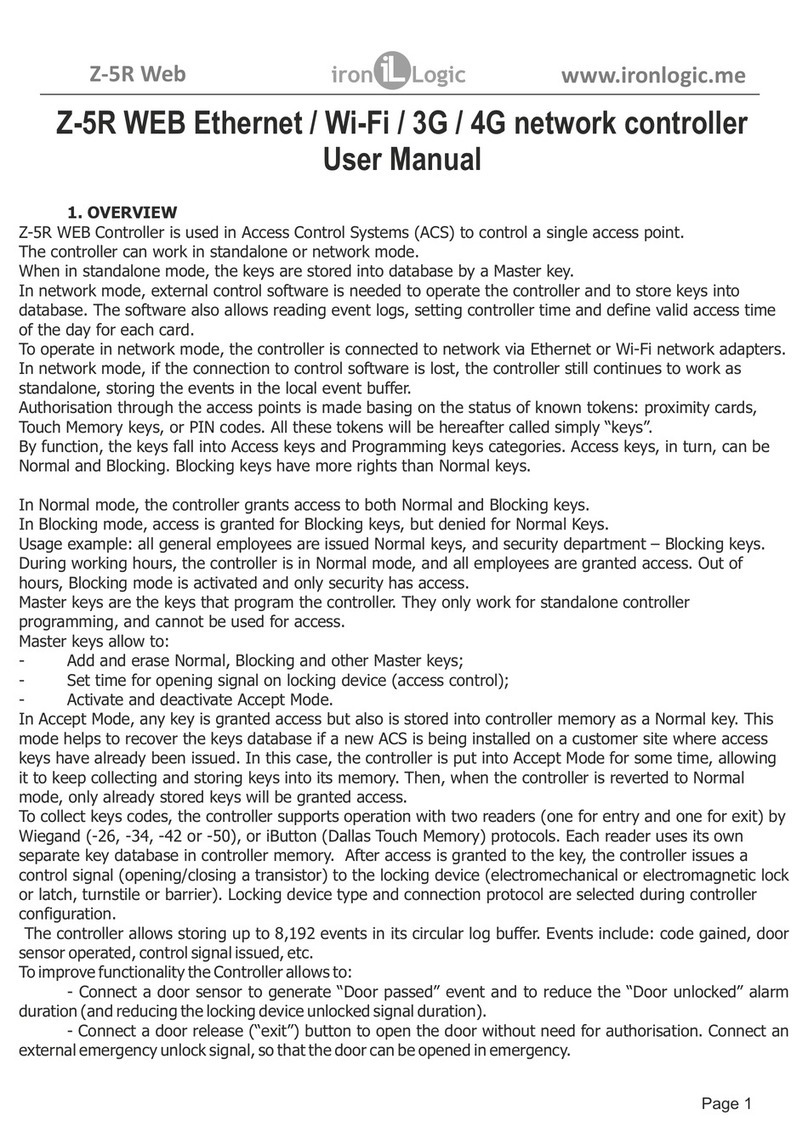
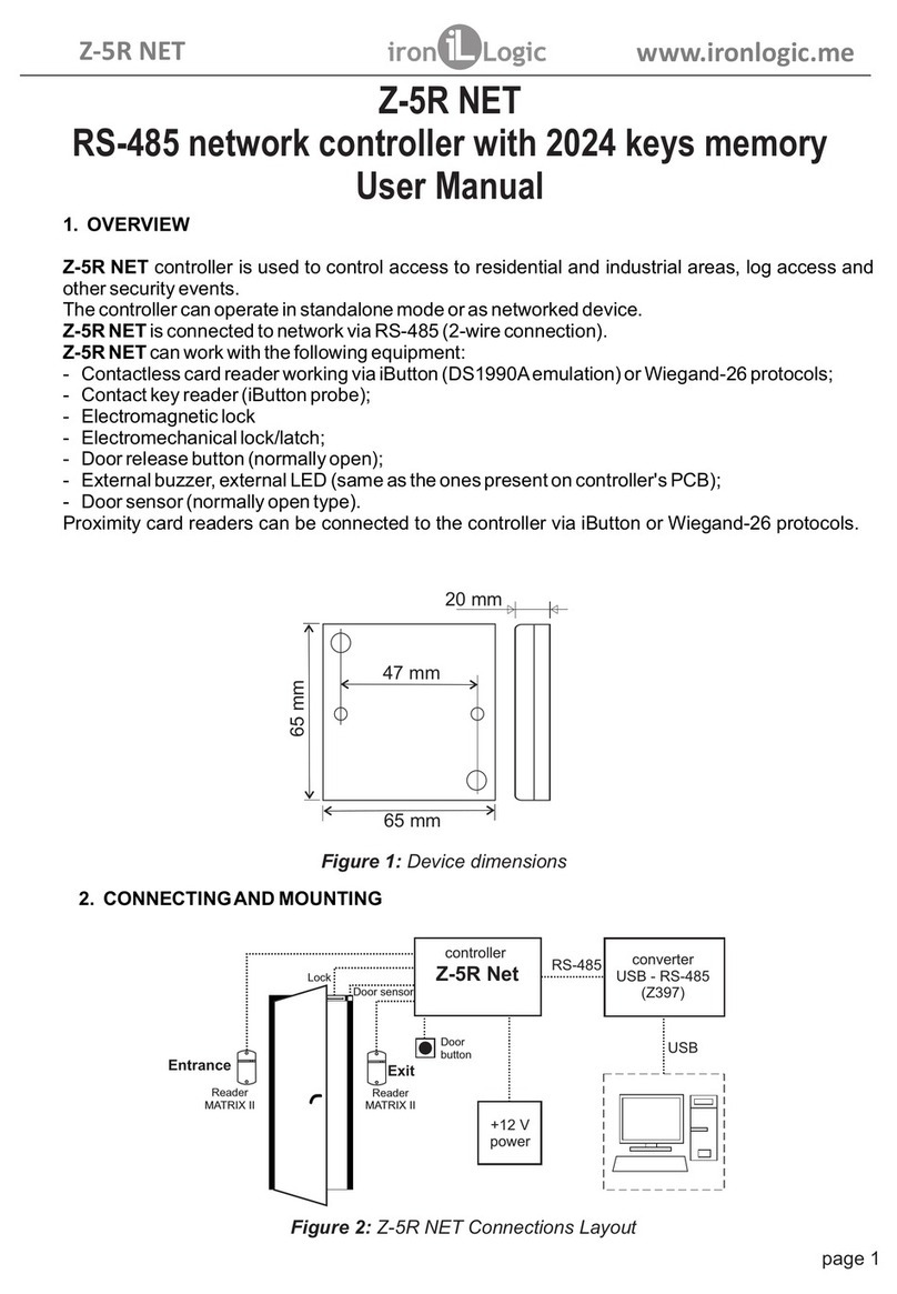
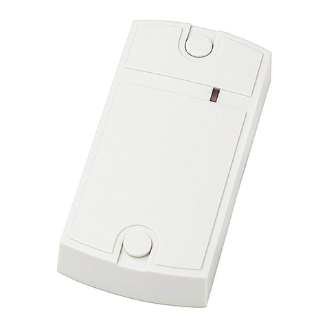
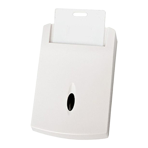
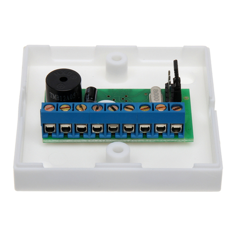
Iron logic Matrix III NET User manual

Matrix III NET network (RS-485) controller
with built-in Mifare (13,56 MHz) reader
User Manual
1. GENERAL INFORMATION
Matrix III NET device is designed to read Mifare keys (cards, key fobs, etc. as per ISO 14443-
A), and to read and write protected memory sectors of Mifare 1K, 4K and Ultralight.
2. OPERATION MODES:
2.1 ACS Reader.
The device is connected to ACS (Access Control Systems) controllers via iButton (Dallas Touch
Memory), Wiegand-26 or Wiegand-34 protocols.
Mode 2.1.1. The device transmits UID (Serial Number) of all cards (keys).
Mode 2.1.2. The device transmits UID (Serial number) of only those cards (keys) that have
authorised (obtained access) to a certain sector.
Mode 2.1.3. The device transmits the code from protected memory sector of a Mifare key.
(To configure 2.1.2 and 2.1.3 modes, download and use free software from M3NConf.zip archive at
http://www.ironlogic.me
2.2 PC Reader.
The Reader is connected to a PC through a converter, via RS-485 protocol.
Mode 2.2.1. The reader reads and writes protected memory sectors of Mifare keys.
To work with the reader in this mode, use the SDK Z-2 USB MF libraries at
http://www.ironlogic.me
To configure 2.1.2 and 2.1.3 modes, and to work in 2.2.1 mode, a Z-397 converter is necessary
(http://www.ironlogic.me
The reader is connected via point-to-point RS-485 (not a network connection).
page 1
MATRIX III NET www.ironlogic.me
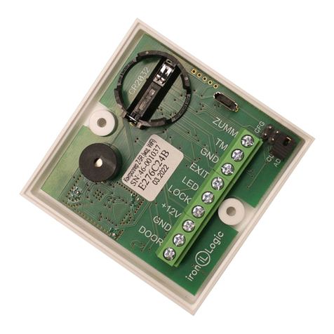
Figure 1. Elements layout.
To increase
the built-in beeper
volume, please remove
the paper sticker.
Jumper layout
for this model.
Lithium battery socket
(not used in this model).

3. READER INSTALLATION AND CONNECTION.
The reader should be mounted on a flat surface so that the keys can easily touch it with no
obstruction.
To mount the reader, perform the following steps:
- Unscrew and take off the top lid;
- Mark and drill the holes of the same size as the mounting holes in the reader (Figure 2);
- Unscrew and take off the bottom lid;
- Lead the wires into the bottom lid and connect them to reader terminals, according to Figure 3
(Connection layout). The red LED indicates that the PCB has been powered.
- Put back and screw the bottom lid in place.
- Install the reader and secure it with screws.
- Put back and screw the top lid.
Note 1: Leave at least 10 cm distance between two readers. If the distance is less than 30 cm, their
working distances can be reduced.
Note 2: To ensure line distance distance as specified in this manual, use a UTP (e.g. CAT5e) cable.
- When connecting via iButton, the wires in twister pair should be connected to GND and
D0 pins.
- When connecting via Wiegand (-26/-34), two twister pairs are connected, the first to GND a nd
D0, and the second to GND and D1 pins.
- When using RS-485, one wire in a twister pair is connected to A and another to B.
page 2
Figure 3. Choosing the transmission protocol.
Figure 2. Device Dimensions.
DATA1
GND
D0DATA0
D1
GND
D0iButton
D1
GND
D0iButton
D1
iButton (One-time transmission)
Wiegand
iButton (DS1990A emulation)
ACS controller
Reader
screw
75 mm
82 mm
115 mm
22 mm
MATRIX III NET www.ironlogic.me
GND
GND
GND

4. READER OPERATION.
When the reader is ready, red LED shines to indicate that power is present.
When Mifare key is brought into reader working zone, its UID is read, and for 2.1.2 and 2.1.3
modes, authorisation is also performed and additional codes are read from key memory.
If reading is successful, the LED will momentarily turn green and a signal will sound. This will
also cause transmission of:
- in 2.1.1 and 2.1.2 modes, the UID just read, and
- in 2.1.3 mode, the code from protected memory sector
into controller, via iButton (Dallas Touch Memory), or Wiegand (-26/-34) protocols, depending on
the configuration.
To configure the device, use the free software from M3NConf.zip archive.
The reader has internal and external LED and sound control.
Internal LED and sound control:
- The red LED is ON when there is no key in reader working zone;
- When a key enters the working zone, red LED goes OFF, green LED turns ON, and a short
beep sounds;
- While a known key is in working zone, no visual indication is present;
- For 2.1.2 and 2.1.3 modes, when an unknown key enters the working zone, red LED goes
momentarily OFF then back ON; no sound is emitted;
- While an unknown key is in the working zone, red LED is ON.
External LED and sound control:
- Comes from a controller, via external control pins (RED, GREEN, SND), or RS-485
commands;
- Turns on by a control signal applied on any of these pins.
Note: Regardless of external control signals, when a key is read, green LED will go ON and
sound will beep for 0.1 second. For 2.1.2 and 2.1.3 modes, when an unknown key is presented
into the working zone, red LED will shortly go OFF and back ON; no sound is emitted.
page 3
Converter
Z-397 GUARD
+12 V
DC
power
Z-397
USB RS 485
Matrix III Net
D0
D1
RED
GND
SND
1. SND External sound control,
2. D0 DATA0 output,
3. GND Ground,
4. D1 DATA1 output,
5. RED External red LED control,
6. +12V +12 V DC power input,
7. GND Ground,
8. GREEN External green LED control.
+12V
GREEN
GND
CLR
ADD
RS-485
ON
A
B
OFF
LOAD
Figure 4. Connection layout.
A
B
MATRIX III NET www.ironlogic.me

5. SPECIFICATIONS.
Working frequency: ..............................................................................................13.56 MHz;
Supported key types: ......................................................................Mifare 1K, 4K, Ultralight;
Working distance: ................................................................................................Up to 6 cm;
Information write into key memory function: .............................................................Present;
Output protocols: ........iButton (Dallas Touch Memory), Wiegand-26, Wiegand-34, RS-485.
Maximum connection line length:
- Via iButton protocol: ............................................................................................up to 15 m
- Via Wiegand (-26/-34) protocol: .......................................................................up to 100 m;
- Via RS-485 protocol: .....................................................................................up to 1,200 m;
Operating mode indication: ........................................................................Audial and visual;
External indication control: .......................................................................................Present;
Power Output: .....................................................................Field-effect Transistor up to 5 A;
Power supply voltage: ..............................................................................................12V DC;
Maximum standby current: .........................................................................................70 mA;
Case material: ........................................................................................Coated ABS plastic;
Dimensions, mm: .............................................................................................115 x 75 x 22;
The reader has the combined inputs and outputs. The direction of an output is selected at a
stage of configuring of the reader by the M3NConf.zip program.
Factory installations: the mode 2.1.1, the transfer protocol is selected by closing of outputs
(Fig. 3), type of a line - on RS-485: Mifare[464B84D4] 1K(0004,08)132,19270, "No Card".
6. OPERATING CONDITIONS
Ambient temperature limits: 5…40°C.
Humidity: no more than 80% at 25°C.
Device specifications may differ from described in this manual when operating not under
recommended conditions.
Device should be operated in absence of: atmospheric precipitation, direct sunlight, sand, dust
and moisture condensation.
7. PACKAGE CONTENTS
Matrix III NET device ...........................1
Mounting Kit .......................................1
8. LIMITED WARRANTY
This device is covered by a limited warranty for 24 months.
The warranty becomes void if:
- This Manual is not followed;
- Device has physical damage;
- Device has visible traces of exposure to moisture and aggressive chemicals;
- Device circuits have visible traces of being tampered with by unauthorised parties.
Under active warranty, the Manufacturer will repair the device or replace any broken parts,
FREE of charge, if the fault is caused by manufacturing defect.
page 4
MATRIX III NET www.ironlogic.me

9. IRONLOGIC CONTACTS
Headquarters:
RF Enabled ID Limited
34 Ely Place, London, EC1N 6TD, UK
E-mail: [email protected]
Development and production:
AVS LLC
7, Bobruiskaya street, Saint-Petersburg, 195009, Russian Federation
E-mail: [email protected]
Phone: +78122411853; +78125421185
www.ironlogic.ru
Authorized representative in the European Union:
SIA IRONLOGIC
79A, Slokas iela, LV-1007, Riga, Latvia
E-mail: [email protected], [email protected]
Phone: +37166181894; +37124422922
www.ironlogic.me
page 5
MATRIX III NET www.ironlogic.me
The symbol of crossed-throught waste bin on wheels means that the product
must be disposed of at f separate collection point. This also applies to the product
and all accessories marked with this symbol. Products labeled as such must not
be disposed of with normal household waste, but should be taken to a collection
point for recycling electrical and electronic equipment. Recycling helps to reduce
the consumption of raw materials, thus protecting the environment.
Table of contents
Other Iron logic Controllers manuals
Popular Controllers manuals by other brands

Digiplex
Digiplex DGP-848 Programming guide

YASKAWA
YASKAWA SGM series user manual

Sinope
Sinope Calypso RM3500ZB installation guide

Isimet
Isimet DLA Series Style 2 Installation, Operations, Start-up and Maintenance Instructions

LSIS
LSIS sv-ip5a user manual

Airflow
Airflow Uno hab Installation and operating instructions
