Iron logic Matrix III 220 User manual

1. OVERVIEW
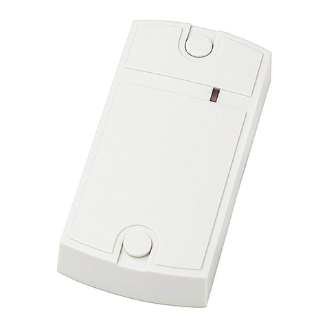
Matrix III 220 Reader is a power relay controlled by contactless cards. The device is a combo
EM-Marine contactless cards reader, and controller with memory up to 500 cards.
The device has a waterproof casing with 2 outgoing cables: 2-wire power supply cable (220 V,
35 mA) and a 3-wire power relay control cable (250 V, 6 A). Also supplied with the device is an
interchangeable pocket accessory that can be attached to the device, to secure the card in
reader working zone.
The device can be used to control power supply in hotel rooms, hostels and dormitories,
outbuildings, business premises, in events planning and property maintenance and decoration
works etc.
Master cards are used to program the device.
Access cards are used to operate the device.
A card becomes a Master card or an Access card during its programming.
2. SPECIFICATIONS
Supply voltage: .............................................................................. 220 V
Consumption current: ...................................................................35 mA
Power relay circuit current: .........................................................max 6 A
Power relay circuit voltage: .....................................................max 250 V
Reader working frequency: ........................................................125 kHz
Cards standard: .....................................................................EM-Marine
Reader working distance: .................................................................6 cm
Maximum cards number: ...................................................................500
Operation mode indication: ...........................................Audial and visual
Casing material: ....................................................................ABS plastic
Dimensions, mm: .................................................................115 x 75 x 27
Device dimensions with the pocket accessory clipped on are illustrated in the Fig.:
page 1
MATRIX III 220 www.ironlogic.me
115
75
27
22
Matrix III 220
Standalone power saving controller
with built-in EM-Marine reader and 500 keys memory
User Manual

3. OPERATION MODES
Switch (green LED). Each touch by an Access card toggles the relay contacts state.
Energy pocket (yellow LED). The relay contacts are closed while a card is located within
reader working zone.
Timed (red LED). Each touch by an Access card toggles the relay contacts state. However, the
contacts are closed no longer than the Release Interval programmed with a Master card.
Device has 3 programming modes: Add Access card, Erase All Cards and Release
Interval Setup.
4. CABLES PURPOSE
Power Supply Cable (2 wires)
Power Relay Control Cable (3 wires)
page 2
№ Wire Colour Pu rpo se
1 Brow n 220 V AC
2 Blu e 220 V AC
№ Wire Co lour Pu rp ose
1 B ro wn NC - N orm ally Clo sed
2 B lack (Mix) CO M – Com mon
3 B lu e NO – Normally Open
Black(mix)
~220V
Blue
Brown
Blue
Brown
MATRIX III 220 www.ironlogic.me

5. MOUNTING AND CONNECTION
The device should be mounted on a flat surface in the location allowing unobstructed access
with cards.
To mount the device using mounting kit, perform the following steps:
1. Unscrew the mounting screw and remove the top device casing lid.
2. Mark and drill two 6 mm holes, each 30 mm deep, in the wall (or other flat surface). Put in the
wall plugs.
3. Connect both cables in accordance with electrical layout. Insulate all wires at the junction
points.
4. Connect the device to power supply and check its operation.
5. Lead both cables, so that they are not jammed when mounting the device. Fix the device
base in position with mounting screws.
6. Put the top casing lid or the pocket accessory in place, and fix it with a screw.
6. PROGRAMMING
6.1 Select Operation Mode
To select an operation mode, touch the device with a Master card no longer than 5 s. Each touch
cycles through the modes: Switch, Energy Pocket, and Timed.
6.2 Select Programming Mode
Touch and hold a Master card to the device. After ~5 s the LED starts blinking green, indicating the
Add Access Card Mode. Continue to hold the card to the device, and after another 5 s the LED
changes into blinking red, indicating the Erase All Cards Mode. After another 5 s of holding the card,
the LED changes into blinking yellow, indicating Release Timer Setup Mode. In further 5 s the
blinking stops and the device returns to its normal operation, the LED will become solid and its
colour will indicate one of the three Operation Modes selected in paragraph 6.1
Holding the Master card further will repeat the cycle through the programming modes described
above: Blinking green, Blinking red, Blinking yellow, solid.
To select a programming mode, take the Master card away when the LED shows the colour
corresponding to the desired programming mode.
6.3 Adding Access Cards
While the LED is blinking green, please take away the Master card from the reader. The LED starts
to blink twice faster, indicating that Add Access Cards Mode is chosen.
Start touching the device with the cards to add as Access cards. When a card is added, the LED will
show steady red shortly. If this won't happen, either the card is already present in the database, or is
of an incompatible standard.
Device will revert to normal operation either automatically in 20 s after the last card touch, or
immediately after a Master card touch.
6.4 Erase All Cards
While the LED is blinking red, please take away the Master card from the reader. The LED starts to
blink twice as often, indicating that Erase All Cards Mode is chosen. It will now wait 20 s for another
Master card touch. If none followed within 20 s, the mode will end and the keys database erase will
be cancelled.
page 3
MATRIX III 220 www.ironlogic.me

To go forward with the erase, touch and hold the Master card: the LED will slowly blink red, then will
flash green once, to acknowledge that all cards, including the Master card, have been erased.
After that, the device will revert into normal operation and indicate its current operation mode by
solid indication of one of three LED colours.
Note: After all cards have been erased, the first card that touches the device will be assigned as a
Master card.
6.5 Setting the Timer *Function is under construction, for details contact
While the LED is blinking yellow, please take away the Master card from the reader. The LED starts
to blink twice more often, indicating that the reader is ready to set the release timer. The current
timer setting will now be displayed.
Timer values are measured in hours (from 0 to 8) and tens of minutes (0, 10, 20, 30, 40, 50). They
are shown as series of LED flashes. Red flashes correspond to hours and green flashes to 10-
minute units. Single yellow flashes separate the series of red flashes and green flashes.
An example of timer display may look like this (R red flash, G green flash, Y yellow flash):
Y RR Y G … (same sequence is then repeated). 2 red flashes stand for 2 hours and 1 green flash
stands for 1 10-minute unit. Total time is 2 hours 10 minutes.
Changing timer value requires a Master card and an Access card. Hours are changed by the
Master card and Minutes are changed by the Access Card.
First touch by each of these cards resets corresponding unit to 0. After that, the hours are set by
desired number of Master card touches, and the 10-minutes units by desired number of Access
card touches. The increments are cyclic, after the maximum value for this unit it will reset to zero and
increment again.
Each card touch changes either red flash number or green flash number. Yellow flashes still work
as separators between the red and green ones.
After 20 s without any card touches, the device will exit the timer value programming (storing the
new timer value).
7. ADDITIONAL INFORMATION
1. After the device has been mounted and connected to the mains power (220 V AC), the LED
indicator runs indicate self-diagnostic: for 3 s it shines solid yellow. Then LED changes display
accordingly to selected operation mode.
2. The Master card is used only for device programming and never for access control. Only one
Master card exists.
3. In the delivery package, six cards are found, initially all already pre-stored to device card
database: one coloured (assigned Master card) and five whites (assigned Access cards). After
Erase All Cards operation, the first card that touches the reader is stored as the Master card. To
prepare device for use, at least one Access card must be added as well.
4. After the power supply was lost and later restored, the chosen operation mode and all the
settings are retained.
5. Before external devices are to be connected to the power relay outputs in Switch and Timer
modes, please check that the initial contacts state is correct (closed or open).
In Energy Pocket mode, the contacts state always corresponds to one described in paragraph 4.
page 4
MATRIX III 220 www.ironlogic.me

8. PACKAGE CONTENTS
Reader Matrix III 220 .........................1
Matrix III Pocket Accessory ...............1
Master Card (coloured) ......................1
Access Card (white) .......................... 5
Mounting Kit .......................................1
9. OPERATING CONDITIONS
Ambient temperature limits: 5…40°C.
Humidity: no more than 80% at 25°C.
Device specifications may differ from described in this manual when operating not under
recommended conditions.
Device should be operated in absence of: atmospheric precipitation, direct sunlight, sand,
dust and moisture condensation.
10. LIMITED WARRANTY
This device is covered by a limited warranty for 24 months.
The warranty becomes void if:
- This Manual is not followed;
- Device has physical damage;
- Device has visible traces of exposure to moisture and aggressive chemicals;
- Device circuits have visible traces of being tampered with by unauthorised parties.
Under active warranty, the Manufacturer will repair the device or replace any broken parts,
FREE of charge, if the fault is caused by manufacturing defect.
page 5
MATRIX III 220 www.ironlogic.me
11. IRONLOGIC CONTACTS
Headquarters:
RF Enabled ID Limited
34 Ely Place, London, EC1N 6TD, UK
E-mail: [email protected]
Development and production:
AVS LLC
7, Bobruiskaya street, Saint-Petersburg, 195009, Russian Federation
E-mail: [email protected]
Phone: +78122411853; +78125421185
www.ironlogic.ru
Authorized representative in the European Union:
SIA IRONLOGIC
79A, Slokas iela, LV-1007, Riga, Latvia
E-mail: [email protected], [email protected]
Phone: +37166181894; +37124422922
www.ironlogic.me
page 6
MATRIX III 220 www.ironlogic.me
The symbol of crossed-throught waste bin on wheels means that the product
must be disposed of at f separate collection point. This also applies to the product
and all accessories marked with this symbol. Products labeled as such must not
be disposed of with normal household waste, but should be taken to a collection
point for recycling electrical and electronic equipment. Recycling helps to reduce
the consumption of raw materials, thus protecting the environment.
Table of contents
Other Iron logic Controllers manuals