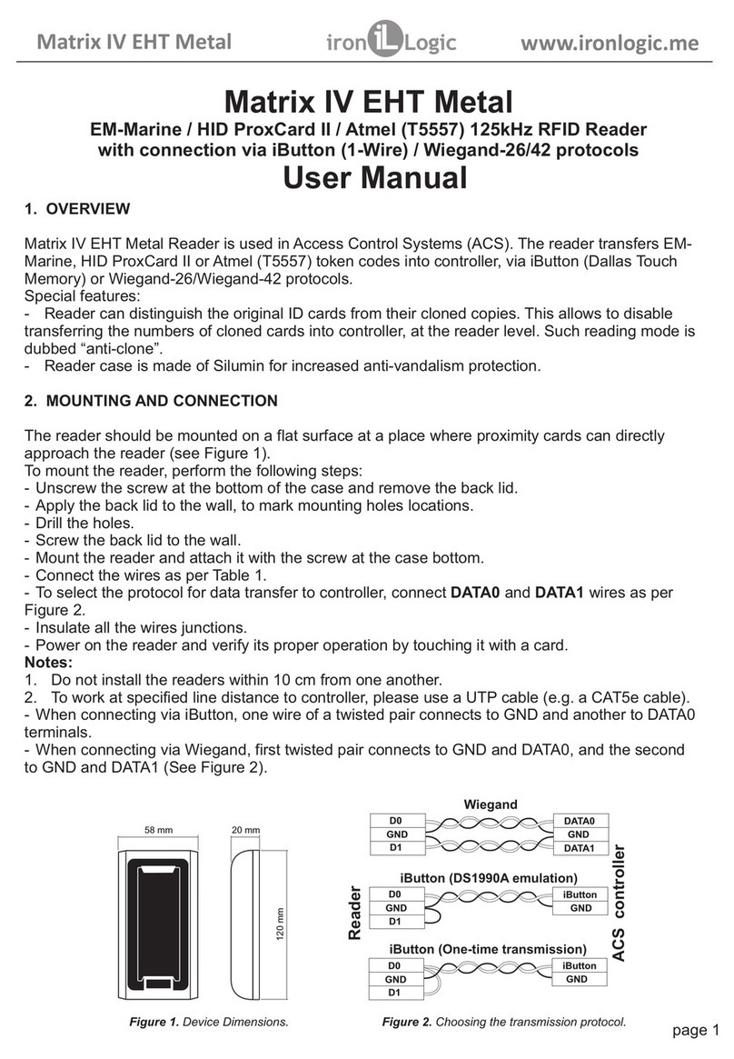
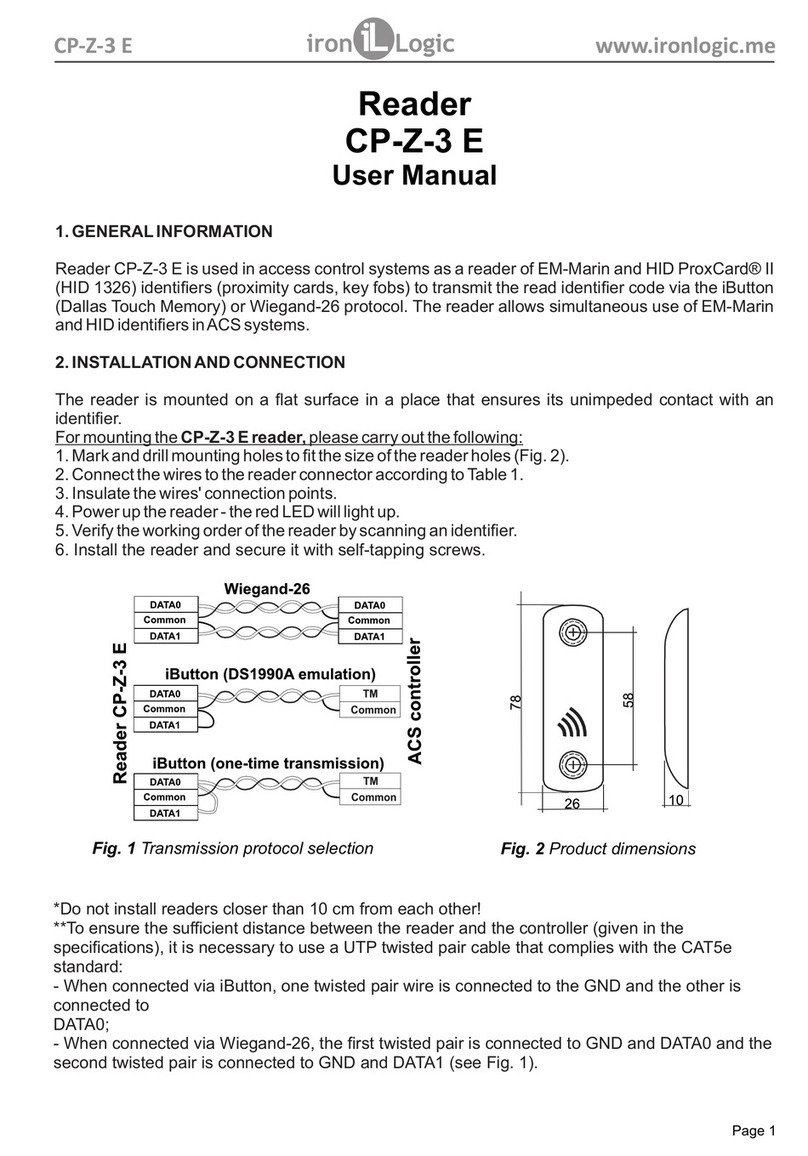
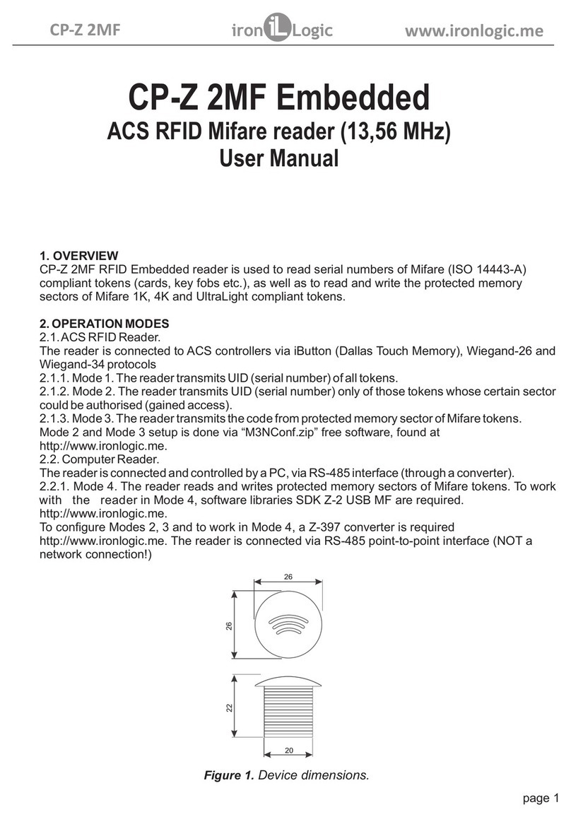
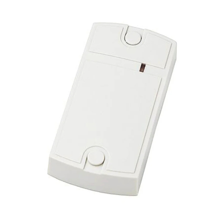
Iron logic Matrix V User manual

MATRIX V
User Manual
EM Marine 125KHz RFID / UHF 433.92 MHz reader with connection
via iButton (1-Wire) / Wiegand-26 / RS-485 protocols
1.
2.
3.
OVERVIEW
Matrix V reader
SPECIAL FEATURES
MOUNTING AND CONNECTION
is used in Access Control Systems (ACS) to:
- read the serial numbers of various EM-Marine tokens (cards, key fobs etc.) operating on 125 kHz
frequency,
- accept the radio signals of KeeLoq tokens operating at 433,92 MHz frequency,
- transmit the acquired information to the controller using iButton (Dallas Touch Memory),
Wiegand-26 or RS-485 standard.
Improved EM-Marine cards reading distance up to 50 cm.
Ability to read the codes off the radio key fobs based on HCS-300 chip, operating using KeeLoq
standard on 433,92 MHz frequency.
Reader casing is moisture-proof.
RS-485 output allowing to connect the reader to a remote PC via Z-397 converter across
very large distances (up to 1,200 m).
Each reader has a unique serial number required during its firmware update by the user.
The reader should be mounted on a flat surface protected from direct sunlight and precipitation,
allowing for easy access by a proximity card.
series
page 1
MATRIX V www.ironlogic.me
Figure 1.Dimensions.
170 mm
225 mm
36 mm
170 mm
225 mm

To mount a MATRIX V reader perform the following steps:
- Mark and drill the mounting holes of the same size as the holes in the reader casing;
(Figure 1);
- Connect the wires per Figures 2, 3, 4, 5.
- Insulate the junction points.
- Power on the reader and verify its proper operation by approaching it with a card or pressing
a key fob button.
Before turning on the reader, please ensure that no other cards on 125 kHz working
frequency are present in the working zone!
- Install the reader at its designated place and fix it.
Do not install readers within 50 cm from each other!
To ensure proper operation over line distances closer to specification limits, use a UTP
cable (e.g. CAT 5e). It should be connected as follows:
- When connecting via iButton: one wire from the twisted pair is connected to GND and the
other one to DATA0;
- When connecting via Wiegand-26: first twisted pair connects between GND and DATA0,
second one - between GND and DATA1. (Figure 3).
- When connecting via RS-485: one wire from the twisted pair is connected to Input A, and the
other to Input B (Figure 4).
When mounting on a metal surface, the actual maximum reading distance may turn out
to be much lower than specified. To enable better reading distance, please place a layer of
dielectric material (such as plywood), at least 2 cm thick, under the reader.
When the reader is powered on, it requires 3…5 s to initialise itself (indicated by both red and
green LEDs being lit). Afterwards, the lone solid red LED indicates that the reader is ready.
The reader has internal and external control of audial and visual indication.
When indication control is internal:
- No card in working area: solid red LED;
- Card enters the working area: a green flash and a short buzz;
- Card remains in the working area: no indication.
External indication control is turned on when a signal from controller is detected on any of the
indication control inputs. External control is performed by connecting the control wire to
common wire.
When a token's serial number is read, the green LED will always light up and a 100 ms buzz will
sound.
The acquired token serial number is transmitted to DATA1 and DATA0 outputs when working via
iButton or Wiegand-26, depending on a chosen transmission protocol (Figure 4), or to“Input A”
and“Input B”when RS-485 is used (Figure 5).
When the reader is connected to a PC by RS-485 protocol via Z-397 series converter, the card
standard and Wiegand-26 serial number are displayed in HyperTerminal window.
For that, HyperTerminal needs to be set up to work with the reader as the serial port using the
following parameters: Baud Rate: 9600, Data Bits: 8, Parity: None, Stop Bits: 1, Flow control:
None.
To display the device's serial number on the screen, press“I”button on PC keyboard.
Note 1:
Note 2:
Note 3:
Note 4:
4. OPERATION
page 2
MATRIX V www.ironlogic.me
Cable 1(7 wires):
- provides power for the device;
- provides iButton (Dallas TM) and
Wiegand-26 outputs;
- used for external LED and sound control.
Cable 2 Layout:Connection to PC, RS-485
Cable 1 Layout: Connection to Controller
Cable 2(4 wires):
provides RS-485 output.
Figure 2.Reader view.back
Jumperneeds to be cut to disable the
reader sound.
Figure 3.Wires purpose.
page 3
Wire Colour Wire Purpose
Black Input A Converter connection
ue
Red Output A External 120 Ohm resistive load,
Yellow or next device in chain.
Bl Input B
Output B
Wire Colour Wire Purpose
+12 V DC
Common (-)
DАТА1
External control, green LED
External control, red LED
External control, buzzer
Red
Black
Brown
White DATA 0
Green
Yellow
Blue
MATRIX V www.ironlogic.me
5. SPECIFICATIONS
6. PACKAGE CONTENTS
Working frequencies: ...........................................................................125 kHz; 433,92 Mhz;
Supported token types: .............................................EM-Marine, 433,92 MHz radio key fobs;
Maximum reading distance:
- For EM-Marine cards: .............................................................50 cm (with IL-05ELR cards);
- Radio key fobs: ...................................................................5 m (with IL-100 radio key fobs);
Output protocols: ...............................iButton (Dallas Touch Memory), Wiegand-26, RS-485;
Maximum line distance to controller by protocol:
- iButton .......................................................................................................................15 m;
- Wiegand-26 ..............................................................................................................100 m;
- RS-485 ............................................1,200 m. (Z-397 converter use recommended);
Operation mode indication:.........................................................................Audial and Visual;
External indication control: ................................................present for both Audial and Visual;
Power supply voltage: ..............................................................................................12 V DC;
Maximum consumption current: ................................................................................500 mA;
Dimensions, mm: ............................................................................................225 x 225 x 36;
Casing material: .........................................................................................................Plastic;
Weight: ......................................................................................................................1.10 kg.
MATRIX V Reader ...........................1
IL-05ELR EM-Marine card ........................1
IL- Radio Key Fob ...............................1
Series
RFID
100
Boutput
Aoutput
Converter
Z-397
USB
R
A
Y
Figure 5. Connection scheme via RS-485.
DATA1
DATA0
DATA0
DATA1
TM
Wiegand
ACS controller
ReaderMATRIX V
DATA0
DATA1
DATA0
DATA1
TM
Figure 4.Choosing the transmission protocol
Z
BBinput
Ainput
page 4
iButton (One-time transmission)
iButton (DS1990A emulation)
Common
Common
Common
Common
Common
Common
ReaderMATRIX V
RS-485
MATRIX V www.ironlogic.me
120 Om

7. OPERATING CONDITIONS
8. LIMITED WARRANTY
Ambient temperature: …°C40°C
Humidity: Not exceeding 80% at 25°C
The reader should not be operated where the following exists: atmospheric precipitation, direct
sunlight, sand, dust and moisture condensation.
Reader specifications may not fully be as specified, when operating under non-recommended
conditions.
This device is covered by a limited warranty for 24 months from the date of sale.
The warranty becomes void if:
- This Manual is not followed;
- Device has physical damage;
- Device has visible traces of exposure to moisture and aggressive chemicals;
- Device circuits have visible traces of being tampered with by unauthorised parties.
Under active warranty, the Manufacturer will repair the device or replace any broken parts, FREE of
charge, if the fault is caused by manufacturing defect.
-30
9. CONTACTS
page 5
MATRIX V www.ironlogic.me
The symbol of crossed-throught waste bin on wheels means that the product
must be disposed of at f separate collection point. This also applies to the product
and all accessories marked with this symbol. Products labeled as such must not
be disposed of with normal household waste, but should be taken to a collection
point for recycling electrical and electronic equipment. Recycling helps to reduce
the consumption of raw materials, thus protecting the environment.
Authorized representative in the European Union
ICONTROL SIA
Slokas iela 79A, LV-1007, Riga, Latvia
E-mail: [email protected]
Phone: +37124422922
www.ironlogic.me
Table of contents
Other Iron logic RFID System manuals

Iron logic
Iron logic Matrix II EH User manual

Iron logic
Iron logic Z-2 USB MF User manual

Iron logic
Iron logic CP-Z-3 E User manual

Iron logic
Iron logic Matrix II User manual

Iron logic
Iron logic Matrix-IV RF User manual

Iron logic
Iron logic CP-Z 2MF User manual

Iron logic
Iron logic Matrix IV EHT Metal User manual

Iron logic
Iron logic MATRIX-V Instruction manual

Iron logic
Iron logic CP-Z-1 GSM User manual