manuals.online logo
Brands
  1. Home
  2. •
  3. Brands
  4. •
  5. Nedap
  6. •
  7. RFID System
  8. •
  9. Nedap TRANSIT Entry User manual

Nedap TRANSIT Entry User manual

TRANSIT Entry Quick Reference
The following safety precautions should be observed during normal use, service and repair.
•The TRANSIT Entry must be connected with safety ground.
•The TRANSIT Entry may only be installed and serviced by
qualified service personnel.
•Disconnect the power supply before removing or installing any parts.
•To be sure of safety, do not modify or add anything to the TRANSIT Entry
other than mentioned in this installation guide or indicated by NEDAP N.V.
Safety precautions
The TRANSIT Entry can be mounted to any surface, including directly onto metal.
Locate an appropriate position. Use the upper two keyholes (K) to mount the
reader. Open the service cover to secure the reader using the two lower mounting
positions (L). See the mounting sketch for more information.
Step 1 Mounting instructions
Open the screws on the bottom of the TRANSIT Entry to unlock the service cover.
Make sure the screws are completely opened (and closed when replacing the
cover). Don’t worry about losing the screws, they cannot fall out.
Step 2 Opening the service cover
Safet
y
precaution
s
The following safet
y
precautions should be observed during normal use, service and repair
.
2
Connection procedure with spring cage terminal connectors.
1. Strip wire lead for about 9 mm (0.35 inch).
2. Push the screwdriver straight down to release the spring cage.
Use a slotted, narrow-head screwdriver.
3. Insert the wire lead into the wire terminal.
4. Remove the screwdriver, this clamps the wire.
5. Gently pull on the installed wire to make sure the connection is reliable.
Note 1: Each connector terminal can accommodate only 1 solid or stranded wire.
Note 2: Wiring is normally done without ferrules. However, it is possible to
use ferrules, provided that they are properly crimped.
Step 3 Connections
The TRANSIT Entry requires DC power supply in the range from 12 - 24V.
Connections:
DC-
Power supply 0V. Should be connected to a protective earth connection.
DC+ Power supply 12 - 24VDC.
Note: The power supply connection has an auto resetting fuse protection.
Step 3.1 Power supply
The synchronous communication interface wiring depends upon the
selected communication protocol and the reader firmware. Please refer to
the firmware manual for more details.
Note: Maximum cable length 150 meters (500 feet)
Step 3.2 Wiegand, magstripe,
barcode connection
OUT1 OUT2 OUT 3 GND
Wiegand
Data-0 (green) Data-1 (white) Ground (black)
Magstripe Card Loaded Clock Data Ground
Barcode Data Ground
The TRANSIT Entry has an on-board RS232 interface, see firmware
manual for details.
Wire
lead
Screwdriver Power
supply
K5
K2
K3
K5
contact
supply
DATA-0
DIN9
Female to host
DATA-1
GND
Step 3.3 RS232 connection
Step 4 Digital I/O
The relay output is automatically activated upon identification of a
transponder,refer to the firmware manual for more details. The ‘smile’
on the front cover lights-up simultaneously with the relay output.
Connections:
NC Relay contact normally closed
COM Relay contact common
NO Relay contact normally open
Step 4.1 Relay output
Contact ratings:
Max. switching current: 2A
Max. switching voltage: 250VAC /220VDC
Max. switching power: 62.5VA /60W
3.2
3.3
4.1
K5
3.1
W
Wi
3
Frequency
selection
DIP
switch
K2 K5 K3 K4
RX LEVEL LED bar indicating the received tag signal strength.
This LED bar may also indicate the presence of radio
interference. In case of interference (2 or 3 LEDS),
try switching to a different frequency.
RDIS Read Disable LED. On while reading disabled.
IN1 Input 1 status. On when input 1 contact is closed.
TXD Transmit serial data (RS232, RS422, USB, I/F-board).
RXD Receive serial data (RS232, RS422, USB, I/F-board).
ID Identification. Blinks fast when a valid transponder
is identified.
STS Status LED.
System’s heartbeat (0.8 sec on / 0.8 sec off). Indicates that
the power is on and the processor is running.
Bootloader says hello. Indicated after a restart.
Configuration menu active.
Abnormal situation.
SQ-ENA Squelch enabled.
SQ-ACT Squelch active.
DC-HI Power supply voltage too high.
DC-LO Power supply voltage too low.
DC-FAIL Internal supply voltage failure.
T-CRIT Temperature critically high.
PLL UL PLL unlocked. Try switching to a different frequency.
5
5.1
5.2
5.3
Step 5.3 Standard Wiegand
The function of the switches SW2-1 through SW2-8 is dependant upon
the installed firmware. Please refer to the firmware manual for details.
The switches SW1-1 through SW1-4 are described below.
The beeper indicates transponder identification. The signal strength
of the identified transponder determines the beeping frequency.
The switches SW1-3 and SW1-4 are reserved for future use, leave these
switches in the ON position.
Step 5.2 RS232 / RS422 Selection
Step 5.1 Range beeper ON / OFF
Table 1 describes the function of each LED.
Step 6 LED indications
Step 5 DIP-SWITCH settings
Range beeper ON
SW1
SW1
SW2
SW1
SW1
RS232 enabled RS422 enabled
Range beeper OFF
6
When two or more readers are within a range of 15 meters (50 feet),
these readers should be set on a different operating frequency.
The selected frequency has to comply with local radio regulations.
1. Press the UP or DOWN switch once.
2. The display will show a value indicating the currently selected
frequency, see table
3. When the display is on, press UP to select a higher frequency
and press DOWN for a lower frequency.
4. The display will automatically switch off after 5 seconds.
Step 7 Frequency selection
Display
value
Frequency
(GHz)
Wifi
50 2.4384
51 2.4390
52 2.4396
53 2.4402
54 2.4408
55 2.4414
56 2.4420
57 2.4426
58 2.4432
59 2.4438
5A 2.4444
5B 2.4450
5C 2.4456
5D 2.4462
5E 2.4468
5F 2.4474 CH8
60 2.4480
61 2.4486
62 2.4492
63 2.4498
64 2.4504
65 2.4510
66 2.4516
67 2.4522 CH9
68 2.4528
69 2.4534
6A 2.4540
6B 2.4546
6C 2.4652
6D 2.4558
6E 2.4564
6F 2.4570 CH10
Headquarters
Nedap AVI
PO Box 103
7140 AC Groenlo
The Netherlands
Parallelweg 2e
7141 DC Groenlo
The Netherlands
T: +31 544 471 666
F: +31 544 464 255
E: [email protected]
Americas
Nedap US Office
500 W. Main, Suite 301
Branson, MO 65616
USA
T: 417 339 7368
F: 417 337 8889
E: info-[email protected]om
Asia
Nedap Asia Office
583 Orchard Road
#16-01/17-01 Forum
Singapore 238884
T: +65 683 280 51
F: +65 683 280 52
E: info-asia@nedap.com
www.nedapavi.com
Nedap, a unique company
Nedap - founded in 1929 and based in the Netherlands - employs approximately 550 people
worldwide. Our shares are listed on the Euronext Stock Exchange. Nedap is an innovative,
solution-oriented company with a wide range of products, systems and services based
on RFID technologies. Our systems are used in a wide variety of markets, offering the
ultimate solution in secure and reliable vehicle and driver identification.
7

Other manuals for TRANSIT Entry

3

Other Nedap RFID System manuals

Nedap uPASS REACH User manual

Nedap

Nedap uPASS REACH User manual

Nedap uPASS TARGET User manual

Nedap

Nedap uPASS TARGET User manual

Nedap NVITE User manual

Nedap

Nedap NVITE User manual

Nedap uPASS Access User manual

Nedap

Nedap uPASS Access User manual

Nedap LibAssist User manual

Nedap

Nedap LibAssist User manual

Nedap Transit Ultimate User manual

Nedap

Nedap Transit Ultimate User manual

Nedap ANPR LUMO User manual

Nedap

Nedap ANPR LUMO User manual

Nedap VP1007-B User manual

Nedap

Nedap VP1007-B User manual

Nedap TRANSIT Entry User manual

Nedap

Nedap TRANSIT Entry User manual

Nedap MidRanger + Antenna Set User manual

Nedap

Nedap MidRanger + Antenna Set User manual

Nedap PROX-BOOSTER 2G User manual

Nedap

Nedap PROX-BOOSTER 2G User manual
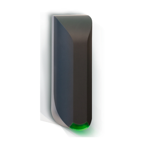
Nedap TRANSIT User manual

Nedap

Nedap TRANSIT User manual

Popular RFID System manuals by other brands
XPR Access MTPX-RS-MF user manual

XPR Access

XPR Access MTPX-RS-MF user manual

microsensys iID PENsolid UHF user manual

microsensys

microsensys iID PENsolid UHF user manual

Iron logic Matrix IV EHT Metal user manual

Iron logic

Iron logic Matrix IV EHT Metal user manual

Advanced Card Systems ACR40T user manual

Advanced Card Systems

Advanced Card Systems ACR40T user manual

TransCore Encompass 5 Quick reference card

TransCore

TransCore Encompass 5 Quick reference card

Invengo XC-RF300 user guide

Invengo

Invengo XC-RF300 user guide

Feig Electronic ID ISC.PRH101-A installation manual

Feig Electronic

Feig Electronic ID ISC.PRH101-A installation manual

Shuttle BR06 Calibrations and Settings

Shuttle

Shuttle BR06 Calibrations and Settings

HARTING Ha-VIS RFID RF-R400 System manual

HARTING

HARTING Ha-VIS RFID RF-R400 System manual

suprema XPD2-GKDBS installation guide

suprema

suprema XPD2-GKDBS installation guide

Omron V700 series Operation manual

Omron

Omron V700 series Operation manual

Elatec TWN4 MultiTech 2 HF user manual

Elatec

Elatec TWN4 MultiTech 2 HF user manual

Clou CL7206C2 user manual

Clou

Clou CL7206C2 user manual

Asterisk AsReader ASR-032W user manual

Asterisk

Asterisk AsReader ASR-032W user manual

Kiwitron KiwiCross Gate K006950 Installation, use and maintenance manual

Kiwitron

Kiwitron KiwiCross Gate K006950 Installation, use and maintenance manual

Bibliotheca 210 owner's manual

Bibliotheca

Bibliotheca 210 owner's manual

Elatec TWN4 MULTITECH 3 LEGIC M LF HF user manual

Elatec

Elatec TWN4 MULTITECH 3 LEGIC M LF HF user manual

ThingMagic Mercury 5 user guide

ThingMagic

ThingMagic Mercury 5 user guide

manuals.online logo
manuals.online logoBrands
  • About & Mission
  • Contact us
  • Privacy Policy
  • Terms and Conditions

Copyright 2025 Manuals.Online. All Rights Reserved.