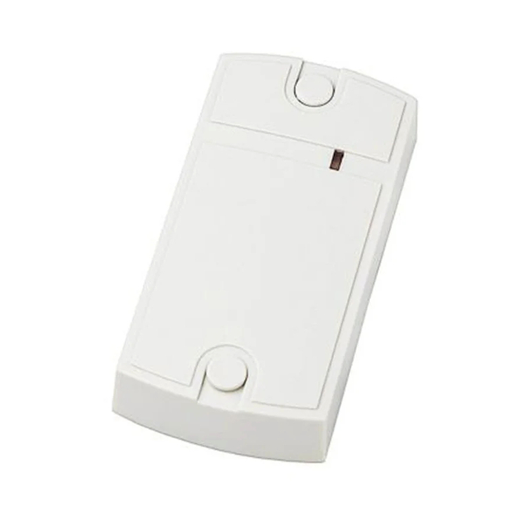
Iron logic Matrix-IV RF User manual

Matrix IV RF
UHF 433.92 MHz reader with connection via
iButton (1-Wire) / Wiegand-26 / RS-485 protocols
User Manual
1. OVERVIEW.
2. MOUNTING AND CONNECTION.
Note:
Matrix-IV RF is used in Access Control Systems (ACS) and can receive
433 MHz signals from radio key fobs and then transmit the decoded serial number (code)
acquired from the key fob to the controller via iButton (Dallas Touch Memory) or Wiegand-26
protocols, or to a PC via RS-485 interface.
The reader should be mounted on a flat surface in a place protected from direct sunlight and
precipitation.
To mount the reader, perform the following steps:
1. Mark and drill the mounting holes of the same size as the holes in the reader casing (see
Figure 1).
2. Connect wires per the layout. Insulate the wire junctions.
3. Power on the reader and check its proper operation by pushing a button on the radio key fob.
4. Mount the reader and fix it in the desired place.
(e.g. CAT 5e) see Figure 2.
- When connecting via iButton, one wire of the twisted pair is connected to GND, and another to
DATA0.
- When connecting via Wiegand-26, two twisted pairs are needed; the first one is connected
to GND and DATA0 and the second one is connected to GND and DATA1.
When connecting via RS-485, one wire of the twisted pair is connected to A, and the other to B
(see Figure 3).
Reading distance may be reduced significantly when the reader is installed directly onto
a metallic surface, or when there are many metal objects around the installation site.
RFID reader
,92
-
To ensure operation at a specified distance from controller, you need to use a UTP cable
Reader features.
Note: In Anti-Clone mode, the reader will work only with IL-100 key fobs
- Decoding the codes of radio key fobs working by KeeLoq and CAME (TOP432NA,
TOP434NA) protocols.
- Adjustable receiver sensitivity allowing for adjustable radio key fobs reception distance.
- Decodes both fixed and dynamic part of KeeLoq code of IL-100 key fobs. This allows for
blocking clone key fobs at the reader level, when operating in Anti-Clone mode.
( ).
- Two output channels to receive key fobs codes, set up separately, allow for flexible ACS
configuration. For example, one reader can be connected to two controllers, and codes from
different radio key fob buttons would be transferred to different channels.
- SMA-F socket to connect an external 433 MHz antenna allows significantly extending the
radio key fobs reception distance by connecting a directional antenna with SMA-M plug.
RS-485 interface allows connecting the reader to a PC to acquire radio key fobs codes and to
configure the reader parameters.
,92
-
Note:
MATRIX IV RF www.ironlogic.me
page 1

125
Cable 1.
-Power
-Wiegand-26 or iButton output.
-RS-485 interface.
Cable 2.
External
antenna
connection.
Fig.1
75
60
Wire Colour Wiegand Connection iButton Connection
Red
Black
Brown DATA0 iButton
Power +12 24 V
Common (-)
Channel 1 Channel 1
White DATA
Green DATA0 iButton
Orange DATA
Blue RS 485
Yellow RS 485
Channel 1 1 Common
Channel 2 Channel 2
Channel 2 1 Common
-А
-В
Table 1.Cable 1 wiring scheme.
IButton
TM
Controller
Reader
Matrix IV RF
Рис.2 Connection, choosing
channel transmission protocol.
R120 Om
Z-397
Common
A
Y
Рис.3Connection via RS-485.
Z
BB
RS-485
Reader
Matrix IV RF
A
Converter
Common USB
USB - RS-485
page 2
Common
Common
MATRIX IV RF www.ironlogic.me

3. OPERATION
Radio link sensitivity adjustment:
Reset to factory default values can be done:
fob fob
The reader has two output channels for key fobs data transmission. For each channel, the following
code transmission parameters values exist:
1) Accepted key fob types:
a) All key fobs;
b) IL-100 key fobs only (Anti-Clone mode)
c) All key fobs except IL-100.
2) Buttons on the key fobs (1,2,3,4) which need to be pressed for key fob code to be transmitted
into the channel.
3) Button pressed code:
a) OFF only key fob code is transmitted;
b) ON the code transmitted depends on the number of the button pressed.
When the reader is connected to the PC via RS-485 interface using Z-397 USB 422/485
converter, -- the reader transmits to the PC the following:
- Type of key fob: (“IRONLOGIC” (IL-100) / “UNKNOWN” (KeeLoq) / “CAME”)
- Key fob code in Wiegand-26 parameter.
Serial port parameters required: baud rate 9600, data bits 8, parity None, stop bits 1, flow
control None.
The Master key fob (IL-100), from the delivery package, is used to adjust radio link sensitivity
and to reset the reader parameters to factory default values. No channels transmit the Master
key fob code.
Pressing the (picture) button on the Master key fob increases sensitivity, whereas the (picture)
button decreases it.
Each button press is confirmed by the reader with a short beep; when adjustment limits are
reached, a double beep is issued.
- via Master key fob, by pressing two buttons at once;
- by connecting Channel 1 DATA0 wire (Brown) to Channel 2 DATA0 wire (Green) and powering
on the reader.
After the factory default values are set, the reader waits for new Master key fob assignment for
15 s. During this time, the status indicator is flashing red and beeps are sounding. To assign a
key fob as a new Master during that period, just press any of its buttons.
fob
The key fob code acceptance is confirmed with sound feedback:
- One beep IL-100 key fob accepted
Two beeps any other key fob accepted.
If during 15 sec. the master isn't appointed, the reader passes into an operating mode with
factory settings.
-
As a master I can be used only IL-100 .
Code transmission parameters is done by configuration software (MIVRFConfig at
www.ironlogic. ) via RS-485 interface, using a Z-397 converter (USB 422/485 model). With this
software, it's also possible to turn off the confirmation beeps on the reader.
Factory default parameter values are:
For Channel 1 IL-100 key fobs only, all buttons, the button code is transmitted alongside key fob
code.
For Channel 2 All key fobs, all buttons, the button code is transmitted alongside key fob code.
me
page 3
MATRIX IV RF www.ironlogic.me
4. SPECIFICATIONS
5.
Working frequency: ...........................................................................................433.92 MHz.
Supported key fob standards: ......................................................................KeeLoq, CAME.
Reading distance from Type IL-100 radio key fobs to a built-in antenna: ...........up to 50 m.
(subject to reception conditions variations).
Channels to transmit the code to controller: .......................................................................2;
Channels to transmit the code to PC: .................................................................................1.
Output interfaces: ............................iButton (Dallas Touch Memory), Wiegand-26, RS-485.
Socket for an external antenna: .................................................................SMA-F standard.
Maximum line distance to the controller:
-Via iButton protocol: ....................................................................................................15 m,
-Via Wiegand-26: ........................................................................................................100 m,
-Via RS-485: ..........................1,200 m (Z-397 USB 422/485 converter use recommended).
Power supply voltage: .......................................................................................12 24 V DC.
Consumption current (at 12 V): ................................................................................100 mA.
Operation mode indication: ........................................................................audial and visual.
Dimensions, mm: ............................................................................................125 x 72 x 22.
Casing material: .........................................................................................................Plastic.
Weight: ........................................................................................................................150 g.
OPERATING CONDITIONS
Ambient temperature: …40°C.
Humidity: Up to 80% at 25°C.
This device should be operated in absence of: atmospheric precipitation, direct sunlight, sand, dust
and water condensation.
Device specifications may differ from described in this manual when operating under non-
recommended conditions.
-30
Status indicator
Channels 1 and 2 indicators
(see Fig. 4) is used to display the current
reader operation mode:
- flashing green standard working mode;
- flashing red waiting for the new Master key fob to be
assigned.
display the transmission
channels state:
- A green flash the key fob code is accepted and transmitted to
corresponding channel.
- A red flash the key fob code is accepted but not transmitted to
corresponding channel: the button is not enabled.
Status indicator
Channel 1 indicator
Channel 2 indicator
Fig. 4
page 4
MATRIX IV RF www.ironlogic.me
6.
Note:
MATRIX-IV ............................... 1
Type IL-100 radio key fob .................................. 1
....................................................... 2
........................................................... 2
External antenna not included.
PACKAGE CONTENTS
7. LIMITED WARRANTY
Screws 3x30
Wall plugs
RFRFID reader
This device is covered by a limited warranty for 24 months from the date of sale.
The warranty becomes void if:
- This Manual is not followed;
- Device has physical damage;
- Device has visible traces of exposure to moisture and aggressive chemicals;
- Device circuits have visible traces of being tampered with by unauthorised parties.
Under active warranty, the Manufacturer will repair the device or replace any broken parts,
FREE of charge, if the fault is caused by manufacturing defect.
8. CONTACTS
page 5
MATRIX IV RF www.ironlogic.me
The symbol of crossed-throught waste bin on wheels means that the product
must be disposed of at f separate collection point. This also applies to the product
and all accessories marked with this symbol. Products labeled as such must not
be disposed of with normal household waste, but should be taken to a collection
point for recycling electrical and electronic equipment. Recycling helps to reduce
the consumption of raw materials, thus protecting the environment.
Authorized representative in the European Union
ICONTROL SIA
Slokas iela 79A, LV-1007, Riga, Latvia
E-mail: info@icontrol.lv
Phone: +37124422922
www.ironlogic.me
Table of contents
Other Iron logic RFID System manuals

Iron logic
Iron logic CP-Z-3 E User manual

Iron logic
Iron logic Z-2 USB MF User manual

Iron logic
Iron logic Matrix V User manual

Iron logic
Iron logic Matrix II EH User manual

Iron logic
Iron logic CP-Z-1 GSM User manual

Iron logic
Iron logic Matrix IV EHT Metal User manual

Iron logic
Iron logic Matrix II User manual

Iron logic
Iron logic MATRIX-V Instruction manual

Iron logic
Iron logic CP-Z 2MF User manual