Iron logic CP-Z-1 GSM User manual

1.
GENERAL INFORMATION
The CP-Z-1 GSM reader is designed for operation in access control systems (ACS) using GSM
cellular communication standard and allows using the telephone number of an incoming call as
an identifier for access control. In addition, incoming SMS messages can also be the source of
the identifier. The identifier obtained in the form of a certain code sequence can be further
transmitted to:
1. A controller via iButton (Dallas Touch Memory) or Wiegand protocols.
2. A personal computer (PC) via RS-485 interface.
Features of the reader:
- Telephone number identification during the call and when receiving SMS messages;
- Reader parameter adjustment using SMS messages;
- RS-485 interface allows connecting the reader to a computer and both receiving codes from
the reader and configuring its parameters;
- A connector for connecting the GSM antenna allows an increased level of network signal
reception by connecting a remote antenna.
2.
INSTALLATION AND CONNECTION
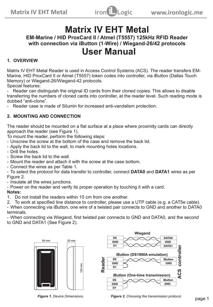
The reader should be mounted on a flat surface in a place protected from direct sunlight and
precipitation.
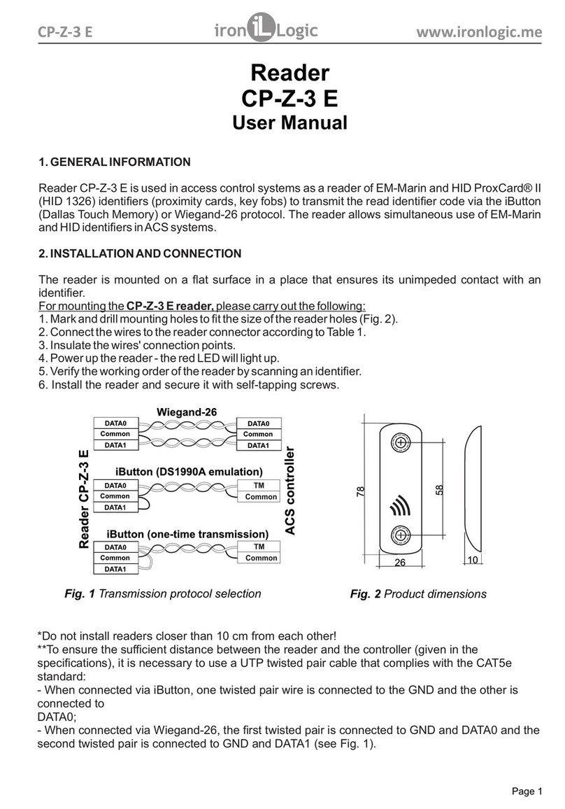
1. Mark and drill mounting holes to fit the size of the reader holes (see Fig. 1).
2. Connect the wires according to the wiring diagram.
3. Insert a SIM card.
4. Install the reader and secure it.
5. Connect the GSM antenna.
6. Turn the power on and make sure that the power indicator "PWR" is on.
To ensure the required distance from the installed reader to the controller provided in the
specifications, it is necessary to use a twisted pair cable (for example, UTP CAT5e).
When connecting via iButton, one twisted pair is connected to the GND terminal and the other
is connected to the D0 terminal (see Fig. 2). Additionally, it is necessary to connect the D1 and
GND terminals with a separate wire. When connecting via Wiegand, two twisted pairs are used.
The first twisted pair connects GND and D0 terminals and the second twisted pair connects
GND and D1 terminals (see Fig. 2). When connected via RS-485, a twisted pair and another
wire are used; the twisted pair connects D0 and D1 terminals and a separate wire connects it to
the grounding GND (see Fig. 3).
CP-Z-1 GSM www.ironlogic.me
Reader CP-Z-1 GSM
User Manual
1
ГАРАНТИЙНЫЕ ОБЯЗАТЕЛЬСТВА
Fig. 1 Product dimensions.
47 mm
65 mm
20 mm
65 mm
ANT
GSM PWR
CP-Z-1 GSM
To increase the volume,
please remove the sticker from the buzzer
4
1
32
SIM
S1
GSM
S0
ANT
GSM
+12V
GND
GND
GND
D1
D0
CP-Z-1
GSM

Purpose of reader terminals:
GND common (ground);
+12V power supply +12…24V;
D0 output DATA0;
D1 output DATA1;
S0 output No.0 (TTL +5V);
S1 output No.1 (TTL +5V).
3. READER OPERATION
3.1 Telephone number identification
To send the required code sequence to the controller, the reader can identify the telephone
number in the following ways:
a) By a call from any telephone number (the telephone number of the caller will be
transmitted to the controller);
b)
By an SMS from the telephone number recorded in its own database of numbers
(the controller will receive a set code: for the administrator - AAAAAAAAAAxx, for the user -
BBBBBBBBBBBBBBXx, where the xx is a serial number of the cell in the database of
administrators or users);
c) By an SMS from any telephone number, except for its own database of numbers
(the code from the text of the SMS message will be transmitted to the controller).
For the identification by a call: Call the number corresponding to the reader's SIM card. The
reader will determine the telephone number of the caller and if such identification is allowed
(see Clause 3.2) the reader will convert this number into the required format and transmit it to
the controller, as well as switch the status of the terminals S0 and/or S1 if the switching
parameters are set and the caller's telephone number is in the reader's database of numbers,
then the reader will reject the incoming call and give 1 short light signal and a sound signal.
For identification by SMS for a telephone number from its own database of numbers:
1) Create a main administrator of the telephone number database and
additional administrators, if necessary (see Clause 3.2);
2) Add a user with the specified telephone number and assign him\her a PIN code
(see Clause 3.2);
2
CP-Z-1 GSM www.ironlogic.me
IButton
TM
Controller
Fig.2 Connection and transmission
protocol selection.
Reader
CP-Z-1 GSM
Reader
CP-Z-1 GSM
Z-397
USB
A
G
B
Converter
RS-485USB -
Fig.3
Connection diagram for RS-485.
D1
D0
GND
GND
D1
D0
GND
GND
D1
D0
GND
GND
Common
Common

- single space;
[
]
-
required parameter;
{} -
optional parameters;
Table 1. SMS commands to configure the database of telephone numbers
Only one of the specified commands is processed in each SMS message.
3)
Send an SMS to the number corresponding to the SIM card of the reader from the user's
number containing the text of his\her PIN code assigned during registration.
The reader will determine the telephone number of the sender of the SMS message and if such
identification is allowed, the reader will find this number in the database of numbers, convert the
code corresponding to the number into the desired format and transmit it to the controller and
also switch the state of terminals S0 and/or S1 if the switching parameters are set, then the
reader will give 1 short light signal and a sound signal.
For identification by text from an SMS received from any telephone number, except for its own
database: send an SMS to the number corresponding to the SIM-card of the reader containing the
text of 6-14 digits. The reader will read the numbers from the SMS message as a telephone number
and if such identification is allowed, the
reader will conv
ert the number into the desired format and
transmit it to the controller, then the reader will give 1 short light signal and a sound signal.
3.2 Configuring the reader
The database of administrator (user) numbers and reader parameters can be configured using
both SMS messages and the RS-485 interface.
3.2.1 Configuring the reader using SMS messages
To configure the reader via SMS messages, you need to register the main administrator and
configure the reader from the main administrator's telephone number. Available SMS commands
for configuration are listed in Tables 1 - 3. Table 4 describes the designation of command
parameters.
Designations in command format:
▊
3
CP-Z-1 GSM www.ironlogic.me
Command Description
[n.pin]admin+ add a main administrator (any PIN code)
[pin]admin+[tel]▊[n.pin]{▊[tel]
▊[n.pin]▊[tel]▊[n.pin]}
add additional administrators (1 to 3)
[pin]admin–[tel]{▊[tel]▊[tel]} delete additional administrators (1 to 3)
[pin]admin? sends a list of additional administrators and their
PIN codes in an SMS reply
[pin]user+[tel]▊[n.pin]{▊[tel]
▊[n.pin]▊[tel]▊[n.pin] ▊[tel]
▊[n.pin]▊[tel]▊[n.pin]}
add a user (1 to 5)
[pin]user–[tel] delete a user
[pin]user–all delete all users
[pin]user? sends a list of users and their PIN codes in an
SMS reply

4
CP-Z-1 GSM www.ironlogic.me
Table 2. SMS commands used to configure the reader parameters.
Command Description
[pin]wieg[bit] set the length of Wiegand
[pin]form▊[format] set the format of code transfer via Wiegand or Dallas
[pin]iden▊call[mode] set the mode of identification by a call
[pin]iden▊sms[mode] set the mode of identification by text in an SMS message
from any number
[pin]iden▊base[mode]
[pin]gpio[terminal]
▊[level]out[time]
set the specified level on the S0 or S1 terminal for the
required time if a number exists in the database of numbers
[pin]sound[mode] reader sound control
[pin]param? sends a list and values of parameters in an SMS reply
1 to 7 specified commands are processed in each SMS message.
The commands are separated by a space character.
Table 3. Other SMS commands.
Only one of the specified commands is processed in each SMS message.
Table 4. Designation of command parameters.
Command Description
[pin]pin[n.pin] replace your PIN with a new one
[pin] when the identification by the database of numbers is allowed,
the set code is sent to the controller
[number]
when the identification by SMS is allowed (except for numbers from
the database), the number from the text of the SMS message is
sent to the controller
Designation
Description Valid
characters
[pin]
The authorisation PIN code of the administrator
or user who executes the query (4 digits) 0 to 9
[n.pin] Any new PIN code for the administrator
or user (4 digits) 0 to 9
[bit] number of bits of Wiegand interface 26, 34, 42, 50, 58
[tel] The added phone number (without the "+"
character or using 8 for RF numbers) 0…9
[format]
format of the telephone number transfer to
the controller:
BCD - binary-coded decimal representation
of the number;
HEX – hexadecimal representation of the number
bcd, hex
[mode] 0 – prohibit the mode, 1 – allow the mode 0, 1
[level] TTL logic signal level 0, 1
[terminal] Terminal number: 0 – terminal S0, 1 – terminal S1 0, 1
[time] time expressed in tenths of a second,
for example, 053 = 5.3 sec (3 characters required),
000 – turn off terminal control
000 to 255
[number] decimal representation of the number (6 to 14
characters) 0 to 9
set the mode of identification by an SMS number received
from the number existing in the database of numbers

The default reader parameters are listed in Table 5.
Table 5. Reader parameters.
To execute any SMS command except for sending a code from an SMS message you must
log in to the reader, i.e. before the command, input the personal PIN code specified when
registering the telephone number in the reader database. In addition, when the reader
executes multiple SMS commands, access rights will be observed, namely:
- The main administrator can send any commands;
- Additional administrators can send any commands except for adding,
deleting and reading of the main and additional administrators.
- Users can only change or send their PIN code;
- Unregistered numbers can only send a code inside an SMS message.
Configuring and updating the reader firmware can be carried out using the configurator
programme for Windows ("GSM Reader Configurator" at www.ironlogic.ru). To connect the
reader to the PC via the RS-485 interface, you must use the interface converter (see Fig. 3).
We recommend the Z-397 Guard USB converter in "NORMAL" mode.
To connect the reader via the RS-485 interface, you should do the following:
- Connect wire A to terminal D0 and wire B to terminal D1 on the switched-off device;
- Combine the grounding of the converter and the reader;
- Set the jumper to position 1 (see Fig. 4);
- Turn on the power.
In this mode, the reader will send a code sequence over RS-485 in plain text.
Examples of SMS commands (by the main administrator):
1. Add the main administrator: 1234admin+
2. Add additional administrators: 1234admin+ 79001112233 4321
79001112255 0000
3. Set level 1 (+5V) on the terminal S0 for 50 msec.: 1234gpio0 1out050
4. Set Wiegand length to 50 bits (6 bytes): 1234wieg50
5. Send the set code for administrators to the controller: 1234
3.2.2. Configuring the reader via the RS-485 interface
5
CP-Z-1 GSM www.ironlogic.me
Parameter Default
parameter
Wiegand format, bit 34
Code transfer format bcd
Identification by a call On
Identification by the SMS text On
Identification by the database number On
Terminal S0 switching time, x0.1 sec. 0
Terminal S0 switching directions 0 to 1
Terminal S1 switching time, x0.1 sec. 0
Terminal S1 switching directions 0 to 1
Reader sound
On
Administrators and users in the database No

Note. The GSM network level is checked every 5 seconds.
3.3 Indication of the operation
The current mode of the reader's operation is displayed by the indicators "PWR" and "GSM"
(see Fig. 1) and their purpose is shown in Table 6.
Table 6. Indication of the reader's operation.
To do this, turn the power off, set the jumper and turn
the power on.
Position 2 - standard position, does not affect the operation of the controller.
If there is no jumper, it shall be deemed to be in position 2.
Position 3 - Not used.
Position 4 - erases the reader's memory. The reader's database of numbers is erased and
the default settings are restored. To do this, turn the power off, set the jumper and turn
the power on. Upon completing the erase, the reader performs a series of short signals.
4. SPECIFICATIONS
Operating frequency: .....................................................................................GSM Standard
Telephone number identification: ..............................................................by call and SMS
Output interfaces: ........................................iButton, Wiegand (26, 34, 42, 50, 58), RS-485
Code transfer format: ...........................................................................................BCD, HEX
Database of numbers, pcs:
administrators .....................................................................................................................4
-Users.................................................................................................................................15
Remote antenna connector: ....................................................................................... SMA-F
Maximum length of the communication line, m:
-Under the iButton protocol ....................................................................... not more than 15
-Under the Wiegand protocol .................................................................. not more than 100
-Under the RS-485 protocol ...................................................................... not more than 10
DC power supply voltage, V: ........................................................................................ 8 - 27
Current consumption (at 12V), not more than, mA: ......................................................... 500
6
CP-Z-1 GSM www.ironlogic.me
Description Indication Sound
"PWR" indicator
Power on (operating mode) Steady green light no
GSM modem malfunction Steady red light no
No SIM card or PIN code set Steady red light no
GSM network not found Steady red light no
"GSM" indicator
Successful registration in the GSM network Blue light flashes 1 time Yes
Successful identification (call or SMS) Blue light flashes 1 time Yes
GSM modem initialisation Blue light flashes repeatedly no
GSM network level is excellent Green light flashes 3 times no
GSM network level is good Green light flashes 2 times no
GSM network level is bad Green light flashes 1 time no
GSM network is lost Red light flashes 1 time no
Fig.4 Positions of jumpers.
3.4. How to use jumpers
The reader comes with one jumper.
It is used for programming and changing the device's mode of operation.
Position 1 -
activates the RS-485 interface on terminals D0 and D1
for changing parameters and updating the reader's firmware via a PC. 4
23
1
Switching current, not more than, mA: ........................................................100
Indication of operating modes: ........................................................sound, light
Dimensions, mm: ................................................................................65х65х20
Case material: ..................................................................................ABS plastic
Weight, g: .......................................................................................................50
1. Reader CP-Z-1 GSM………...............1 pc.
2. Instruction manual .............................1 pc.
3. Jumper ..............................................1 pc.
4. GSM antenna ....................................1 pc.
5. OPERATING CONDITIONS
Ambient temperature: -40°C to + 50°C (during operation, the temperature range of the installed
SIM card should be taken into account).
Relative humidity: not more than 85% at 25°C (without condensation).
When operating conditions change, the technical specifications of the product may differ from
the nominal values. The product is intended for use in the absence of precipitation, direct
sunlight, sand, dust and moisture condensation.
6. PACKAGE CONTENTS
7.
LIMITED WARRANTY
The warranty operation period is 12 months from the date of sale.
Grounds for the termination of warranty liabilities:
- Violation of the requirements of this Operation Manual;
- Existing mechanical damage;
- Existing traces of exposure to moisture and/or aggressive substances;
- Existing traces of unqualified interference in the device's wiring diagram.
During the warranty period, the Manufacturer undertakes to remove malfunctions of the
device caused through the Manufacturer's fault or replace the defective product free of
charge. The service life of the product: 6 years.
8.
CONTACTS
7
CP-Z-1 GSM www.ironlogic.me
Authorized representative in the European Union
ICONTROL SIA
Slokas iela 79A, LV-1007, Riga, Latvia
E-mail: [email protected]
Phone: +37124422922
www.ironlogic.me
The symbol of crossed-throught waste bin on wheels means that the
product must be disposed of at f separate collection point. This also
applies to the product and all accessories marked with this symbol.
Products labeled as such must not be disposed of with normal household
waste, but should be taken to a collection point for recycling electrical and
electronic equipment. Recycling helps to reduce the consumption of raw
materials, thus protecting the environment.
Table of contents
Other Iron logic RFID System manuals

Iron logic
Iron logic Matrix V User manual

Iron logic
Iron logic Matrix II User manual

Iron logic
Iron logic Matrix IV EHT Metal User manual

Iron logic
Iron logic MATRIX-V Instruction manual

Iron logic
Iron logic CP-Z-3 E User manual

Iron logic
Iron logic Matrix II EH User manual

Iron logic
Iron logic Matrix-IV RF User manual

Iron logic
Iron logic CP-Z 2MF User manual

Iron logic
Iron logic Z-2 USB MF User manual