FAILURE TO DO THESE WARNINGS
MAY RESULT IN SERIOUS INJURY
AND/OR PROPERTY DAMAGE.
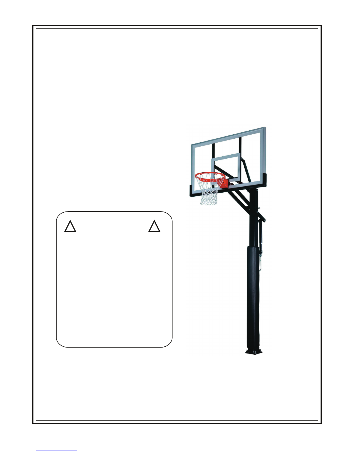
Owner must ensure that all players know
and follow these rules for safe operation
of the system.
Only hang from the rim briefly to regain
balance or avoid injuring others.
Release the rim as soon as possible
safely.
During play, especially when
performing dunk type activities, keep
palyer’s face away from the backboard,
and net. Serious injury could occur if
teeth/face come in contact with
backboard, rim, or net.
Do not slide, climb, or play on pole.
When adjusting height, keep hands
and fingers away from moving parts.
Do not allow children to adjust system.
During play, do not wear jewelry (rings,
watches, necklaces, ets.) Objects may
entangle in net.
Keep water and organic material away
from pole. Pole can rust and fail.
Check pole and all metal parts
regularly for rust. completely remove
rust and repaint with exterior enamel. if
rust has penetrated any steel parts,
replace that part immediately.
Check system before each use for
loose hardware, signs of rust and
instability. Repair before each use.
Never play on damaged equipment.
Wear a mouthguard when playing to
avoid dental injuries.
FAILURE TO FOLLOW THESE WARNINGS MAY RESULT IN
SERIOUS INJURY AND/OR PROPERTY DAMAGE.
FAILURE TO DO THESE SAFETY INSTRUCTIONS MAY RESULT IN
SERIOUS INJURY, PROPERTY DAMAGE AND WILL VOID WARRANTY.
Owner must ensure that all players know and follow these rules for safe
operation of the system.
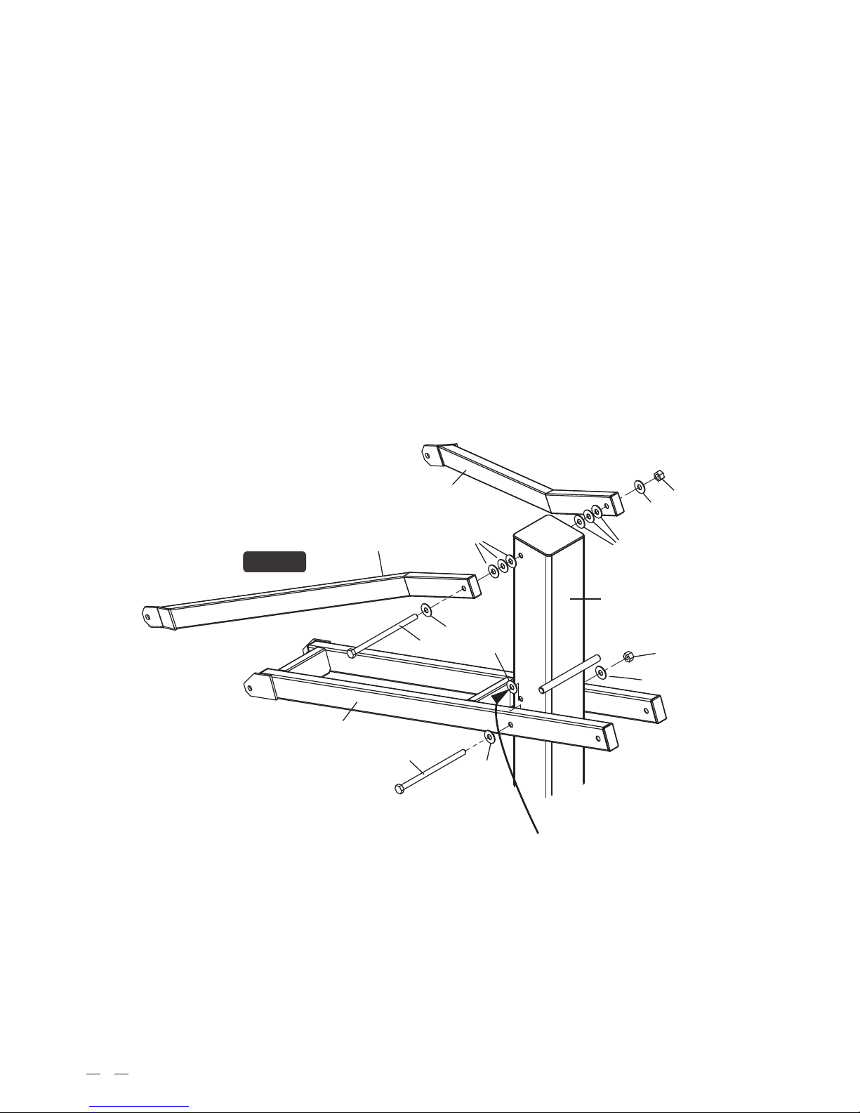
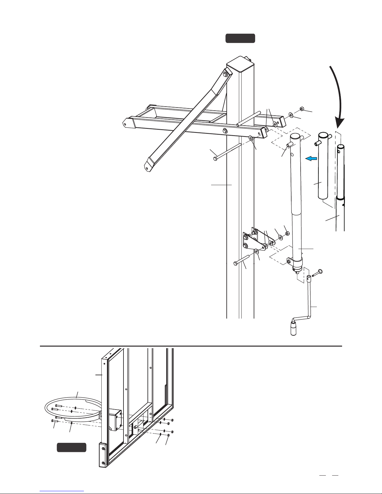
To ensure safety, do not attempt to assemble this system without
following the instructions carefully. Proper and complete assembly, use
and supervision is essential for proper operation and to reduce the risk of
accident or injury. A high probability of serious injury exists if this system
is not installed, maintained, and operated properly.
If use a ladder during assembly, use extreme caution.
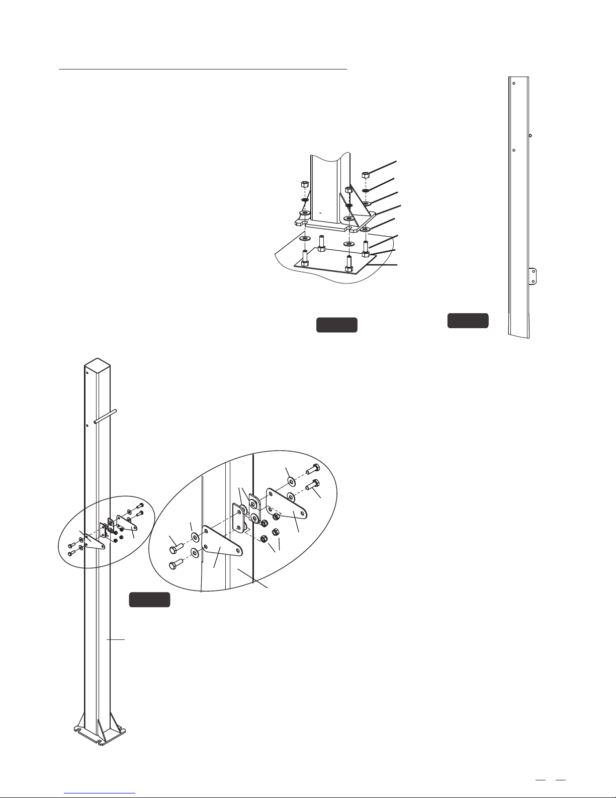
4 people are recommended for this operation.
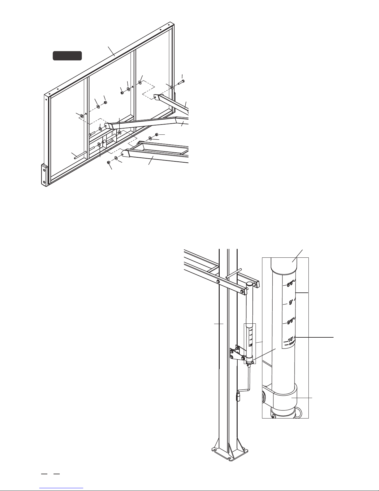
Seat the pole sections properly (if applicable). Failure to do so could
allow the pole sections to separate during play.
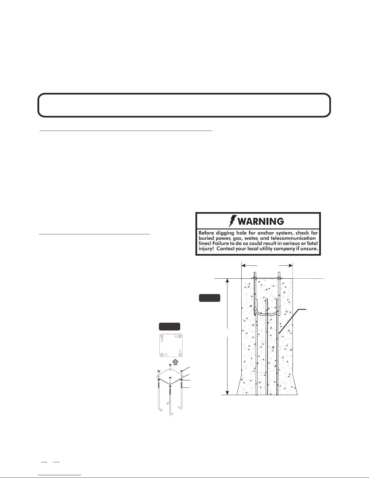
Before digging, contact utility company to locate underground power
cables, gas and water lines. Ensure there are no overhead power
lines within 20 ft. (7m) radius of pole location.
Climate, corrosion or misuse could result in system failure.
If technical assistance is required, contact us:
2