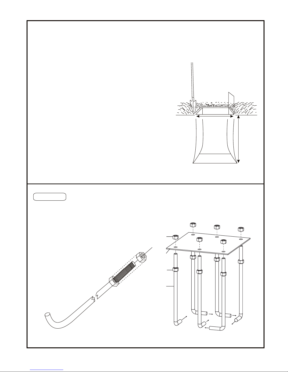
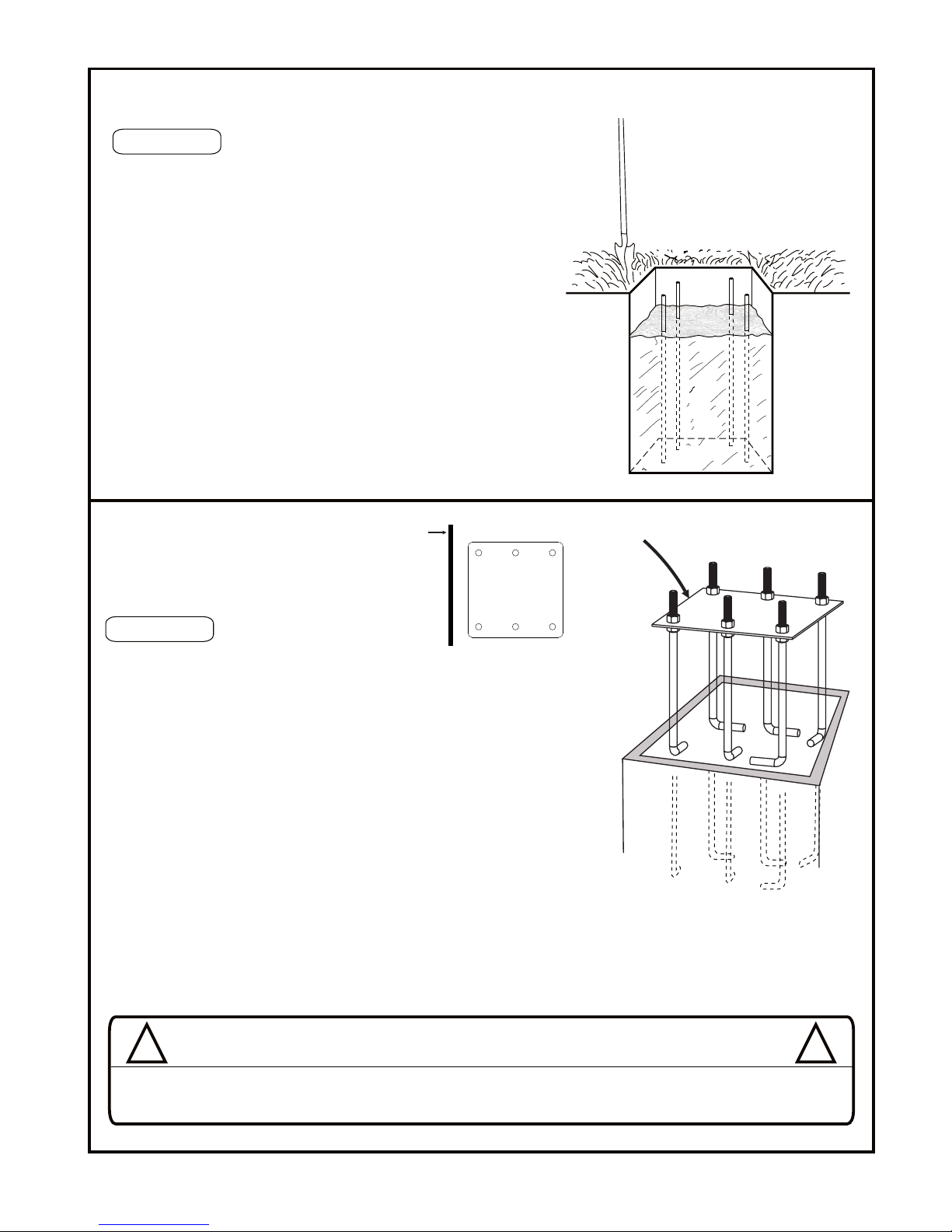
STEP C
STEP D
a. Mix the concrete according to the instructions on the bags. Note that
a thicker mix of concrete will dry stronger than a thin mix. Pour the
concrete into the hole, stopping approximately 18 inches from the top
of the hole.
b. Insert the four pieces of Anchor Rebar (U5) into the hole, pushing each
piece firmly to the bottom of the hole. The four pieces should be
arranged in a square approximately 8 inches wide so that each piece of
rebar will be positioned next to the J-Bolts when the J-Bolt Template
is placed in the cement.
c. Finish filling the hole to the top with concrete. The top of the concrete
should reach just above the level of the top of the form.
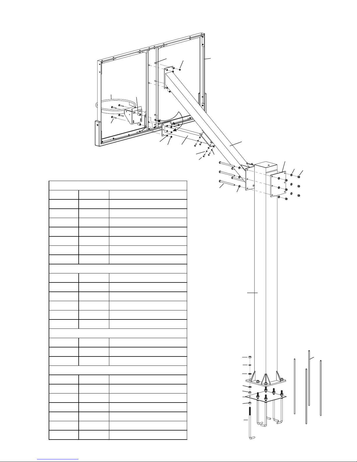
U5
a. Position the J-Bolt Template (U1) over the hole as shown.
with the sides of the plate square with the sides of the hole.
b.Push the J-Bolts (U2) into the concrete until the J-Bolt Template is
resting flat against the surface of the concrete.
c. Grasp the tops of the J-Bolts and agitate the Template assembly back
and forth repeatedly to eliminate any air bubbles in the concrete. Lift the
Template slightly above the concrete when agitating . Make sure the
Template is resting on the concrete after agitating. Form the concrete
into a downward slope away from the Pole to allow water runoff.
d. Clean off any concrete that may be on the J-Bolt Template or the exposed
portions of the J-Bolts.
e. Using a carpenter’
s level, make sure the Template is square to and level
with the playing surface.
f. Allow the concrete to cure for a minimum of 5-7 days before installing
the rest of your basketball system. In cold , wet weather or humid
climates, allow additional time for the concrete to cure.
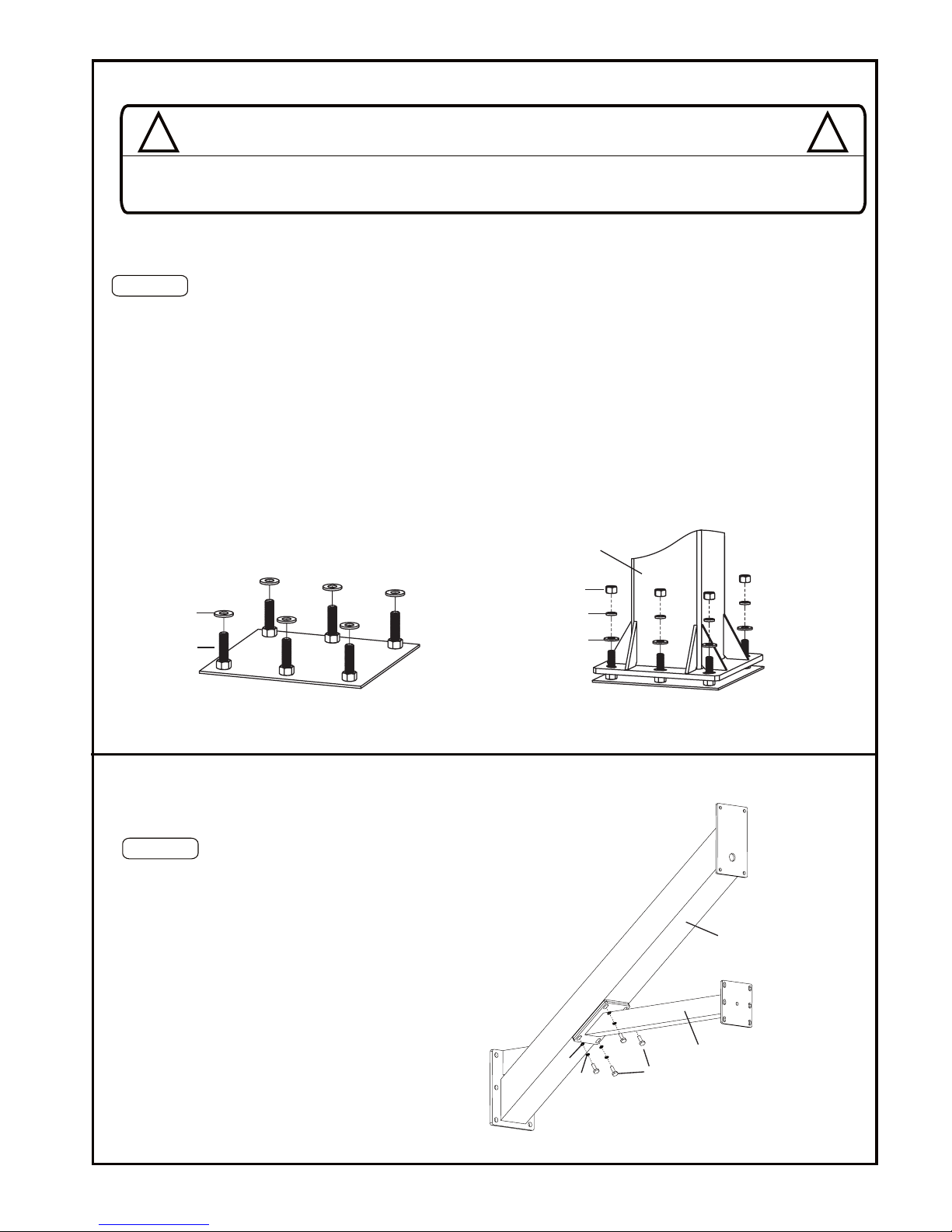
YOU ARE NOW FINISHED WITH THE INITIAL ASSEMBLY STEPS. DO NOT PRO-
CEED WITH THE ASSEMBLY UNTIL THE CONCRETE HAS FULLY CURED . CUR-
ING WILL TAKE A MINIMUM OF 72 HOURS. IN HUMID CLIMATES OR WET
WEATHER, ALLOW ADDITIONAL TIME FOR THE CONCRETE TO CURE.
!!
WARNING
NEVER USE THE SYSTEM WITHOUT FOLLOWING THE CEMENTING INSTRUCTIONS . FAILURE TO
FOLLOW ALL OF THESE INSTRUCTIONS AND WARNINGS COULD LEAD TO SERIOUS PERSONAL INJURY
OR PROPERTY DAMAGE AS LISTED ON PAGE ONE.
5
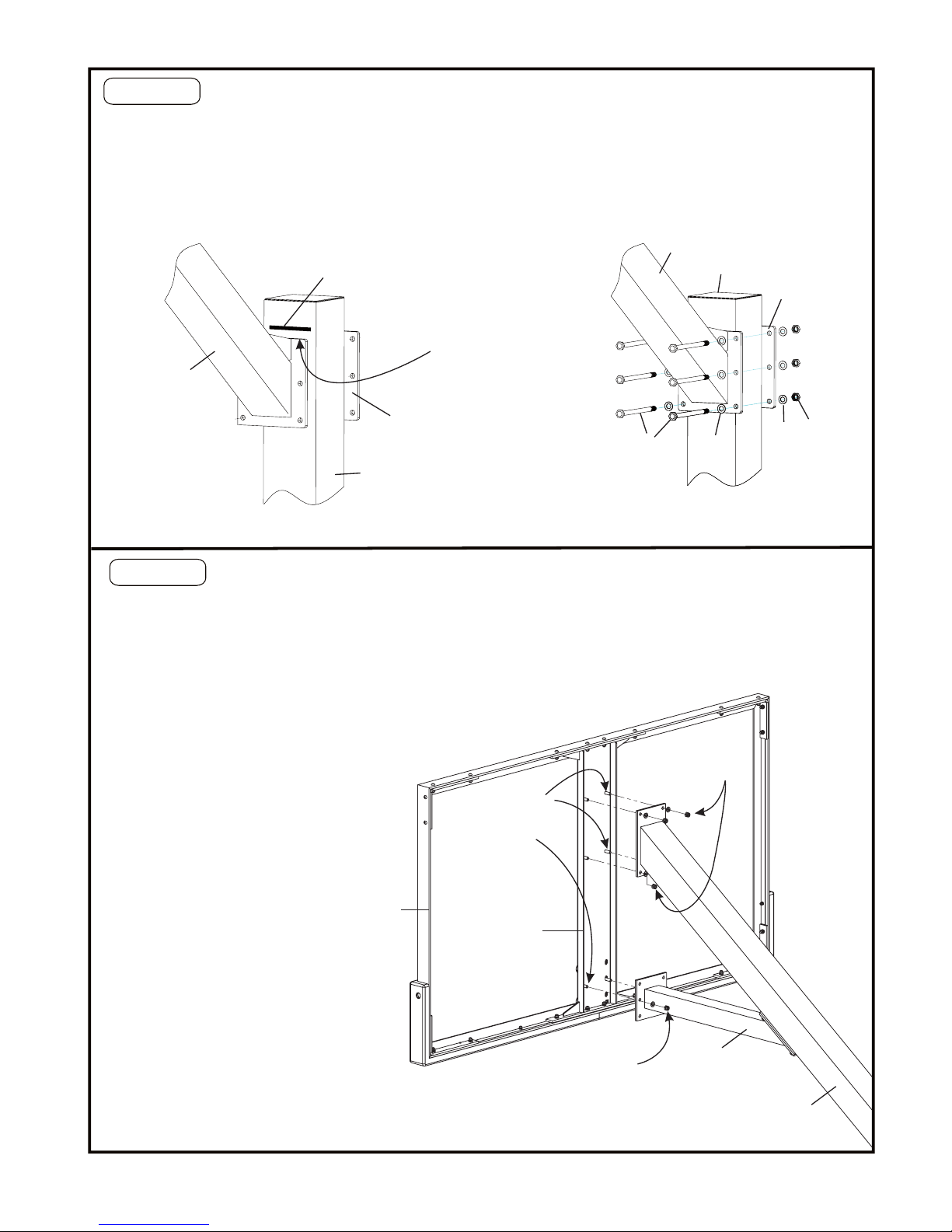
Playing surface
(Front side)
Anchor
template
Edge of
playing surface
This side faces
playing ground