ironwear 2408-SSH-LE Operator's manual

USER INSTRUCTION MANUAL
SRL SELF-RETRACTABLE LIFELNE
WITH LEADING EDGE
MODELS: 2408-SSH-LE, 2408-ARH-LE,
2430-SSH-LE, 2450-SSH-LE, 2465-SSH-LE
WARNING:
This product is part of a personal fall arrest, work positioning, or rescue system.
The user must follow the manufacturer's instruction for each component of the system.
This instruction must be provided to the user of this equipment.
Manufacturer's instructions must be followed for proper use and maintenance of this
equipment. Alterations or misuse of this product or failure to follow instructions may result in
serious injury or death. This equipment is intended to be used by persons trained in its correct
application and use.

1
IMPORTANT:
If you have questions on the use, care, or suitability of this equipment for your application, contact
Ironwear: 800-329-2235, 2020 Seabird Way, Riviera Beach, FL 33404
Before using this equipment, record the product identification information from the ID label and RFID tag in
the inspection and maintenance log of this manual.
DESCRIPTION:
Material: aluminum, Galvanized steel cable wire, Thermoplastic Housing, Stainless steel & non-corrosive
components, zinc-plated steel, high-strength ABS, and polyester.
Modal No#
Length
Type
Description
2408-SSH-LE
8'
Backpack
Type
3/16" Galvanized cable SRL w/snap hook. includes Back pad,
connector
2408D-SSH-LE
8'
3/16" Galvanized cable Twin SRL w/snap hook. Includes Back pad,
connector
2408-ARH-LE
8'
3/16" Galvanized cable SRL w/aluminum rebar hook.
Includes Back pad, connector
2408D-ARH-LE
8'
3/16" Galvanized cable Twin SRL w/ aluminum rebar hook.
Includes Back pad, connector
2430-SSH-LE
30'
Hanged
Type
3/16" Galvanized cable SRL w/snap hook, Swivel Top.
2450-SSH-LE
50’
3/16" Galvanized cable SRL w/snap hook, Swivel Top.
2465-SSH-LE
60'
3/16" Galvanized cable SRL w/snap hook, Swivel Top.
LIMITATIONS:
Capacity:
The SRL-LEs are designed for use by one person with a combined weight (person, clothing, tools, etc.) of up
to 310 lbs. (141kg) for all application including leading edge.
The SRL-LEs may be used for capacities up to 420lbs (190kg) in limited applications but not for Leading
Edge.
Overhead Use Non-Leading Edge Application:
Capacity Range: 130 lbs –420 lbs
Average Arresting Force: 1,350 lbs(2408-LE), 900 lbs(2430-LE,
2450-LE, 2465-LE)
Maximum Arresting Force: 1,800 lbs
Max arrest distance: 24”(2408), 54”(2430-LE, 2450-LE, 2465-LE)
Free fall: not permitted
Min. fall clearance: 6.5’
Class A (2408-LE), Class B (2430-LE, 2450-LE, 2465-LE)
Leading Edge Use Application:
Capacity Range: 130 lbs –310 lbs
Min. setback distance from edge: 0’
Min. fall clearance: 17’- 21’
Max arrest distance: 54”–102”
Free fall: 5’Max

2
Connector:
Connectors must be compatible in size, shape, and strength.
Self-closing, self-locking connectors are required by ANSI and OSHA.
-5000 lbs. (22.2 KN) for non-certified anchorages.
-Two times the maximum arrest force permitted when certification exists
Compatibility:
Connecting Component Limitations:
A Competent Person must ensure the compatibility of all connections and that of the system.
If any other component in the system doesn’t operate properly or if any connector doesn’t lock, don’t use
the system.
Don’t use if any part of the system appears to be damaged, or a body belt for fall arrest applications.
All connector gates withstand minimum loads of 3,600 lbs.
See the following for examples of incompatible connections:

3
INSPECTION FREQUENCY:
SRL-LEs shall be inspected by the authorized person or rescuer before each use.
Inspection shall be conducted by a competent person other than the user.
The competent person shall use Inspection Schedule and checking list for appropriate inspection intervals
and procedures.
Results of the Competent person inspection should be recorded in the " Inspection and Maintenance Log"
on the back pages of instruction.
APPLICATIONS:
Purpose:
This product is part of a personal fall arrest, restraint, work positioning, suspension, or rescue system.
A Personal Fall Arrest System (PFAS) is typically composed of an anchorage and a Full Body Harness (FBH),
with a connecting device, i.e., a Shock Absorbing Lanyard (SAL), or a Self-Retracting Device (SRL), attach to
the dorsal D-ring of the FBH.
SRL-LEs are designed for use in applications where falls may occur, including falls over edges, such as
roofing, leading edge construction, etc.
SRL-LEs covered by this manual, SRL-LEs may be used in many situations where a combination of work
mobility and fall protection is required. (i.e. inspection work, general construction, maintenance work, oil
production, confined space work, etc.)
The 2408D-LE incorporate two SRL-LE units that can be used for application where 100% tie-off is required.
Standards:
SRL-LEs confirm to the national standard identified on the label. Refer to local, state, and federal
(OSHA)requirements governing occupational safety for additional information. The standard is ANSI
Z359.14 - Safety Requirement for Self-Retracting Device for Personal Fall Arrest and Rescue Systems.
Free Fall:
When anchorage overhead, SRL-LEs will limit the free fall distance to 2ft. (61cm) or less.
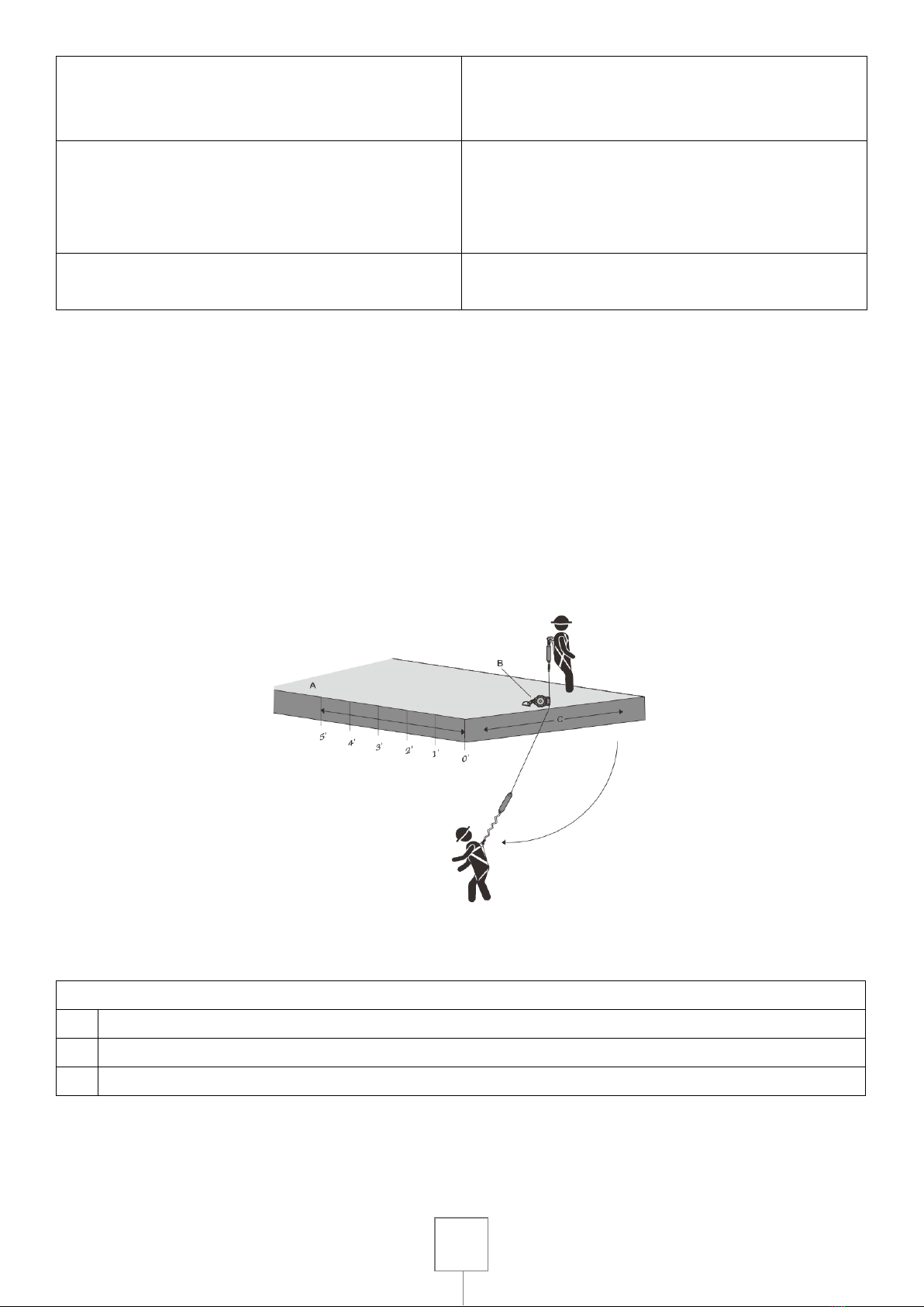
To avoid increased fall distances, anchor the SRL-LE directly above the work level.
Avoid working where your lifeline may cross or tangle with that of another worker.
Never clamp, knot, or prevent the lifeline from retracting or being taut.

4
Angle of Redirection:
The angle of redirection is the angle of the lifeline over an edge during a fall event.
Install the SRL so that the angle of the two parts of the lifeline are at least 90∘, or more, but never less.
The lifeline must never rise up to the edge as it may bend the lifeline in too small a radius and/ or severely
abrade, or otherwise compromise, the lifeline.
Leading Edge Angle of Lifeline Redirect
A
OK- 90∘Minimum Angle over Leading Edge
B
OK- Greater than 90∘Minimum Angle over Leading Edge
C
Not OK- less than 90∘Angle over Leading Edge
Swing Falls:
Swing falls occur when the anchorage point is not directly above the point where a fall occurs. The force of
striking an object in a swing fall may cause serious injury. In a swing fall, the total vertical fall distance will
be greater than if the user had fallen directly below the anchorage point, thus increasing fall clearance
required to safely arrest the user.
Minimize swing falls by working as directly below the anchorage point as possible.
Never permit a swing fall if injury could occur.
Drawing 1.

5
Swing Fall Hazards Non- Leading Edge
A
Anchorage
B
Self-Retracting Lifeline
C
Walking/ Working Surface
D
Swing Fall impact after fall event
E
Next Lower Level or Obstruction
Fall Clearance:
Calculate SRL-LE MRFC Anchorage: 5' Setback From Leading Edge
5' Below the Dorsal D-ring.
With the anchor set back and below the D-ring, there are seven variables to consider when calculating the
MRFC. These seven are labeled A, B, C, D, E, F and G, H is the MRFC.
These variables are:
A= Free Fall Distance due to Below D-ring Anchorage.
B= SRL deceleration distance.
C= Dorsal D-Ring shift and FBH Stretch
D= Additional Deceleration Distance.
E= Safety Factor
F= Sub Total- Minimum Required Fall Clearance.
G= Additional Fall Clearance Calculation for swing fall- 4' maximum.
H= Minimum Required Fall Clearance.
The MRFC for this anchorage geometry is calculated as A+B+C+D+E=F (Sub-total MRFC)
If a swing fall condition exists, use Chart 1 to determine the amount of swing fall present.
The value is the G variable G+F=H.
Drawing 2.

6
Calculating Minimum Required Fall Clearance SRL-LE
Anchorage: 5' Minimum Setback from Leading Edge and 5' below Dorsal D-ring
A- 5ft: Free fall Distance- due to Below D-ring
Anchorage
E- 11/2ft: Safety Factor- Added length to account for
other factors such as an improperly adjusted
harness, actual worker height or worker weight.
B- 3ft: SRL Deceleration Distance
F- 14ft: Sub Total- Minimum Required Fall
Clearance for Below D-ring Anchorage of SRL with
No Swing Fall (sum of A thru E only)
C-1ft: Dorsal D-ring Shift and FBH Stretch
Combined amount of Dorsal D-ring up-shift and
harness webbing elongation during entire fall
event.
G* Additional Fall Clearance Calculation due to
Swing Fall (using Chart 1)
D- 31/2ft: Additional Deceleration Distance- due to
Below D-ring Anchorage
H* Total Required Fall Clearance Including sub-total
F and Swing Fall G (from Chart 1)
Swing Fall with 5' setback:
A swing fall condition is created when the user travels laterally from directly in front of or below the
anchorage, as shown in Drawing 4. For each foot of work zone expansion, the risk of severe injury or death
from a swing fall increase. This increased risk requires additional MRFC distance, up to a maximum of 4' of
added clearance.
If the user exceeds maximum lateral travel, the swing force of a fall event would cause the lifeline to swing
and abrade on the edge, with increased risk of damage to or otherwise compromising the lifeline, resulting
in serious injury or death to the user. Limit potential swing fall abrasion risk by limiting lateral travel.
Drawing 3.

7
Swing Fall Hazard: Leading Edge Condition with 5' Setback
A
Walking/ Working Surface
B
Foot Level Anchorage with 5' Setback from Leading Edge.
C
Expanded Lateral Work Zone with Leading Edge Condition.
See Chart 1 for instruction on how to determine a safe lateral travel distance.
Using Chart 1 to Find Additional Fall Clearance: Leading Edge Conditions
2 foot increments along the X-Axis represent the
distance the user is working away from the SRL
anchorage.
5 foot increments up the Y-Axis represent the SRL
anchorage height above or below the user's Dorsal
D-ring.
At no time shall the expanded Work Zone exceed 16' (8' on each side of center)
Note the starting location on Chart 1 titled Dorsal D-Ring
Example:
The starting point shown is where the SRL is anchored at Foot Level (5' below the Dorsal D-ring) and has
5' of Setback distance from the Leading Edge. From here, the user may expand the lateral work zone up o
8' along the X-axis and still remain inside the allowable and cautionary areas. This expanded work zone
indicates that 4' of additional fall clearance should be added to the Sub-total calculation in Drawing 3.
Drawing 4.

8
If the user needs to expand the work zone to 12', the SRL must be anchored 15' above the Dorsal D-ring
to remain in the allowed and cautionary areas. This change also indicates 4' of additional fall clearance to
be added to Drawing 3.
If the user cannot anchor the SRL above the Dorsal D-ring but still must expand the work zone, the SRL
will need to be anchored with more than 5' of setback distance from the leading edge.
Key to Work Zone Areas: □=Allowable Use Area ■=Cautionary Use Area ■= Not Allowed Use Area
Calculate SRL-LE MRFC Anchorage: 0' Setback From Leading Edge
5' Below the Dorsal D-ring.
With the anchor installed at zero set back and below the D-ring, there are eight metrics to consider when
calculating the MRFC.
These eight metrics are labeled A, B, C, D, E, F, G and H. These metrics are:
A= Free Fall Distance due to Below D-ring Anchorage.
B= SRL deceleration distance.
C= Dorsal D-Ring shift and FBH Stretch
D= Additional Deceleration Distance.
E= Safety Factor
F= Sub Total- Minimum Required Fall Clearance.
G= Additional Fall Clearance Calculation for swing fall- 4' maximum.
H= Minimum Required Fall Clearance.
The MRFC for this anchorage geometry is calculated as A+B+C+D+E=F (Sub-total MRFC)
If a swing fall condition exists, use Chart 1 to determine the amount of swing fall present.
The value is the G variable G+F=H.
Calculating Minimum Required Fall Clearance SRL-LE
Anchorage:0' Setback from Leading Edge and 5' below Dorsal D-ring
A- 5ft: Free fall Distance -due to Below D-ring
Anchorage
E- 11/2ft: Safety Factor-Added length to account for
other factors such as an improperly adjusted
harness, actual worker height or worker weight.
Drawing 5.

9
B- 3ft: SRL Deceleration Distance
F- 171/2ft: Sub Total- Minimum Required Fall
Clearance for Below D-ring Anchorage of SRL with
No Swing Fall (sum of A thru E only)
C-1ft: Dorsal D-ring Shift and FBH Stretch
Combined amount of Dorsal D-ring up-shift and
harness webbing elongation during entire fall
event.
G* Additional Fall Clearance Calculation due to
Swing Fall (using Chart 2)
D-7ft: Additional Deceleration Distance- due to
Below D-ring Anchorage
H* Total Required Fall Clearance Including sub-total
F and Swing Fall G (from Chart 2)
Swing Fall with 0' setback:
A swing fall condition with 0' setback is shown in Drawing 6. For each foot of work zone expansion, the risk
of severe injury or death from a swing fall increase. This increased risk requires additional MRFC distance,
up to a maximum of 4' of added clearance. A swing fall, combined with the user at the maximum allowable
lateral travel, will cause the lifeline to abrade along and across the edge. This may cause severe lifeline or
energy absorber damage over a swing fall, combined with the user at the maximum allowable lateral travel,
will cause the lifeline to abrade along and across the edge. This may cause severe lifeline or energy
absorber damage over a rough, sharp, or abrasive edge. Limit lateral travel to avoid swing falls.
Swing Fall Hazard: Leading Edge Condition with 0' Setback
A
Walking/ Working Surface
B
Foot Level Anchorage with 0' Setback from Leading Edge.
C
Expanded Lateral Work Zone with Leading Edge Condition.
See Chart 2 for instruction on how to determine a safe lateral travel distance.
Drawing 6.

10
Using Chart 2 to Find Additional Fall Clearance: Leading Edge Conditions
2 foot increments along the X-Axis represent the
distance the user is working away from the SRL
anchorage.
5 foot increments up the Y-Axis represent the SRL
anchorage height above or below the user's Dorsal
D-ring.
At no time shall the expanded Work Zone exceed 8' (4' on each side of center)
Note the starting location on Chart 2 titled Dorsal D-Ring
Example:
The starting point shown is where the SRL is anchored at Foot Level (5' below the Dorsal D-ring) and has
0' of Setback distance from the Leading Edge. From here, the user may expand the lateral work zone up
to 4' along the X-axis and still remain inside the allowable and cautionary areas. This expanded work zone
indicates that 4' of additional fall clearance should be added to the Sub-total calculation in Drawing 5.
If the user needs to expand the work zone to 10', the SRL must be anchored 10' above the Dorsal D-ring
to remain in the allowed and cautionary areas. This change also indicates 4' of additional fall clearance to
be added to Drawing 5.
If the user cannot anchor the SRL above the Dorsal D-ring but still must expand the work zone, the SRL
will need to be anchored with more than 0' of setback distance from the leading edge.
Key to Work Zone Areas: □=Allowable Use Area ■=Cautionary Use Area ■= Not Allowed Use Area
Compatibility of Components & Connectors:
ironwear equipment is designed for use with ironwear approved components and subsystems only. Non-
approved components or subsystems may jeopardize compatibility of equipment and may affect complete
system. Connectors (hooks, carabiners, and D-rings) must be capable of supporting at least 5000 lbs.
(22.2KN) Non-compatible connectors may unintentionally disengage.
Per ANSI Z359 and OSHA, self-locking snap hooks and carabiners are required.

11
INSTALLATION:
Anchorage:
For users exceeding 310 lbs. (141kg), anchorage point must not be more than 5ft(1.52m) below the Dorsal
D-Ring. For users exceeding 310 lbs. (141kg), up to 420 lbs. (191kg), the anchorage point must not be more
than 2ft.(0.6m) below the Dorsal D-Ring and higher when connecting off to the user's left or right side.
Harness Mounting:
To mount the Anchor on a full body harness.
1. Compress and hold both release buttons and slide pin to open position.
2. Taking some web out and then loose them beneath harness dorsal D-ring, slide SRL Bracket pin through
loop and lock closed. Retighten web loop after install.
3. Turing whole configuration over in opposite side. Unraveling Hook & Loop and then put strap inside of
the Hook & Loop. Then having Hook & Loop be hidden beneath the web loop.
4. With SRL attached to harness as shown, it is permitted to connect separate connecting device to the
harness dorsal D-ring. However, never work with more than one connecting device connected to an
anchorage connector at any time.
Release
Buttons

12
Use:
ironwear friendly reminder-
Do not alter or intentionally misuse this equipment.
Some subsystem and component combinations may interfere with the operation of this equipment. Use
caution when using this equipment around moving machinery, electrical hazards, chemical hazards, sharp
edges, or overhead materials that may fall onto the lifeline. Do not loop the lifeline around structural
members.
DO NOT extend the lifeline past the operational limit.
DO NOT allow one SRL lifeline to become tangled or twisted with another SRL lifeline during use.
DO NOT allow any lifeline to pass under arms or between legs during use.
DO NOT clamp, knot, or prevent the lifeline from retracting or being taut.
DO NOT lengthen the SRL by connecting a lifeline or similar component.
DO NOT allow the lifeline to remain outside the housing when not in use.
DO NOT allow the lifeline to freewheel back into the housing. Use a tag line to maintain tension and rewind
the lifeline during periods of inactivity.
Use the tag line to retrieve the leg end connector for the next use.
DO NOT leave the tag line connected to the leg end connector when using the SRL for fall protection.
Consult your doctor if there is reason to doubt your fitness to safely absorb the shock from a fall arrest. Age
and fitness seriously affect a worker's ability to withstand falls. Pregnant women or minors must not use
ironwear self-retracting lifelines. Failure to heed this warning may result in serious injury or death.
Operation:
Prior to use, inspect the SRL-LE as described in Inspection sentence. Connect the snap hook, carabiner
attachment to a suitable anchorage. Ensure hooks are fully closed and locked. Once attached, the worker is
free to move about within the recommended working area. If a fall occurs, the SRL-LE will lock and arrest
the fall. Upon rescue, remove the SRL-LE from use. When working with an SRL-LE, always allow the lifeline
to retract back into the device under control.
ironwear friendly reminder-
Do not tie or knot the lifeline. Avoid lifeline contact with sharp or abrasive surfaces. Inspect the lifeline
frequently for cuts, fraying, burns, or signs of chemical damage. Dirt, contaminants, and water can lower
dielectric properties of the lifeline. Use caution near power lines. Failure to heed this warning may result in
serious injury or death.
After A Fall:
If a fall event occurs, tag the SRL as " UNUSABLE", remove it from service, and store it separately. Remove
from service any unit that has been subjected to fall arrest forces or that exhibits damage consistent with
such forces.
Body Support:
A full body harness must be worn when using SRL-LEs. Connect the SRL-LEs to the user's harness shoulder
straps just below the back (dorsal) D-ring.

13
ironwear friendly reminder-
Do not use a body belt for free fall applications. Per OSHA 1926.502 requirement.
Making Connections:
Snap hooks and carabiners used with this equipment must be self-locking. Ensure all connections are
compatible in size, shape and strength. Do not use equipment that is not compatible. Ensure all connectors
are fully closed and locked, ensure unintended disengagement cannot occur.
ironwear connectors (snap hooks and carabiners) are designed to be used only as specified in each
product’s user’s instruction.
Twin Leg 2408 SRL-LE’s:
With the twin leg 2408-LE’s mounted on the back of a Full Body Harness, the user can have continuous fall
protection (100% tie-off) while ascending, descending, or moving laterally. With the lifeline leg of one SRL-
LE attached to an anchorage point, the worker can move to a new location, attach the unused lifeline leg of
the other SRL-LE to another anchorage point, and then disconnect from the original anchorage point. The
sequence is repeated until the worker reaches the desired location. Considerations for twin leg 100% tie-off
applications include the following:
◎ Connection of each SRL-LE leg to a separate anchorage point is acceptable.
◎ Never connect more than one person at a time to the twin-leg system.
◎ Do not allow the lifelines to become tangled or twisted together as this may prevent them from
retracting.
◎ Do not allow the lifelines to pass under arms or between legs during use.
See below picture:
Horizontal Systems:
In applications where the SRL-LE is used in conjunction with a horizontal system. (i.e. Horizontal Lifeline,
Horizontal I-Beams Trolley), the SRL-LE snap hook and horizontal system components must be compatible.
Horizontal systems must be designed and installed under the supervision of a qualified engineer.
Drawing 7.

14
Inspection:
Before each use of this fall protection equipment carefully inspect it to assure it is in good working
condition. Check for worn or damaged parts. Ensure all bolts are present and secure. Check that the lifeline
is retracting properly by pulling out the line and allowing it to slowly retract. If there is any hesitation in
retraction, remove the SRL-LE from service, mark " UNUSABLE". Inspect the lifeline for cuts, frays, burns,
crushing and corrosion. Check locking action by pulling sharply on the line.
Inspection Frequency:
The SRL-LE must be inspected at the intervals. More information could be found in Inspection Schedule and
Checking List.
Product Life:
The functional life of SRL-LE is determined by work conditions and maintenance. As long as the SRL-LE
passes inspection criteria, it may remain in service.
Disposal:
Dispose of SRL-LEs if it has been subjected to fall arrest forces or inspection reveals an unsafe or defective
condition. Before disposing of the SRL-LE, cut the cable lifeline in half or otherwise disable the SRL-LE to
eliminate the possibility of inadvertent reuse.
MAINTENANCE, SERVICING, AND STORAGE
Cleaning: Cleaning procedures for SRL-LEs are as follows:
Ensure the SRL is kept free of excess paint, grease, dirt or other contaminants as this may cause to cable or
retracting mechanism to malfunction. Ensure no debris enters the housing through the cable access port.
Clean the exterior of the unit as required with a detergent/water solution. Do not allow water other
corrosion causing elements to enter the housing. After cleaning, pull the lifeline all the way out, allow the
unit to air dry, then retract the lifeline into the unit. Do not allow the lifeline to freewheel back into the
housing. Tag as " UNUSABLE" and store separately any unit in need of or scheduled for maintenance.
DO NOT use heat to dry.
DO NOT attempt to disassemble the SRL.
Service:
2408-LE is user repairable.
The SRL is designed to be used installed in an anchor cradle or attached overhead. While it may be used
horizontally on a flat surface, the user may encounter a situation where the lifeline will not retract all the
way due to misalignment and bunching up on the drum. If this happens, hang the SRL from a height
sufficient to allow the full working length of the lifeline to be pulled off the drum, then allow the SRL to
retract the lifeline completely. Maintain tension on the lifeline. Use a tag line if necessary.

15
Storage:
Hang the SRL in a cool, dry, clean environment out of direct sunlight. Position the SRL so excess water can
drain out. Avoid exposure to chemical or caustic vapors. Thoroughly inspect the SRL after any period of
extended storage.
Specifications:
SRL-LEs have been tested and certified to the performance requirements of the standard(s) identified on
the labels. SRL-LEs documented in this instruction meet the following Arrest Force and Arrest Distance
maximums when tested in accordance with ANSI Z359.14.
Average Arresting Force
≦ 1350 lbs. (6KN) (FS8015)
≦ 900 lbs. (4KN) (Others)
Maximum Arresting Force
≦ 1800 lbs. (8KN)
Maximum Arresting Distance
24” (FS8015) 54” (Others)
*User weights above 310 lbs. are not within the scope of ANSI/ ASSE Z359.14
The above results are valid when the SRL-LE lifeline is secured overhead. For applications where the SRL-LE
is not secured overhead or where falls may occur over an edge, greater arresting distance will result.
Dimensions:
Average working range for each kind of the SRL-LE is the different, such as the 2408-LE is 8 ft(2.44m), the
2430-SSH-LE are 30 ft (9.1m), 2450-SSH-LE is 50ft (15.2m), and the 2465-SSH-LE is 65ft (19.8m), but will
vary slightly with length differences in the various End Connector options.
Labeling:
Illustrates the SRL-LEs labeling. All labels on the SRL-LE must be present and fully legible.
2408-SSH-LE

16
2408D-SSH-LE
2408-ARH-LE
2408D-ARH-LE

17
2430-SSH-LE
2450-SSH-LE
2465-SSH-LE

18
Anchorage Range of Leading Edge SRL-LE
1. Anchorage of SRL at Foot Level with 0' Setback from Leading Edge.
2. Anchorage of SRL at Foot Level with 5' Setback from Leading Edge.
3. Overhead Anchorage of SRL Above Dorsal D-ring with 0' Setback from Leading Edge.
4. Anchorage of SRL Above Dorsal D-ring with 5' Setback from Leading Edge.
Incorrect Use of Leading Edge SRL
1. Do Not subject cable lifeline to Leading or Sharp Edge during normal use.
2. Do Not anchor SRL on opposite of existing hole or floor opening from work location.
Drawing 8.
Drawing 9.
Drawing 10.

19
Incorrect Use of Leading Edge SRL
A. Heat Damage from Weld Spatter or Slag
C. Broken Wires within Strands.
B. Bird Caged
D. Curled, Bent or Kinked
Indicator
A. The warning label is exposed at outside- immediately remove from service.
B. Broken/ damaged indicator stitching- immediately remove from service.
C. Intact indicator stitching- OK to use.
Inspection requirements for self-retracting devices
ANSI Z359.14-2014
Type of
use
Application
examples
Example conditions of
use
Worker
inspection
frequency
Competent
person
inspection
frequency
Product
revalidation
frequency
Infrequent
to Light
Rescue and
confined
space, factory
maintenance
Good storage
conditions, indoor or
infrequent outdoor
use, room
temperature, clean
environments.
Before each use
Annually
At least every 5
years but not more
than intervals
required by the
manufacturer.
Moderate
to Heavy
Transportation,
residential
construction,
utilities,
warehouse
Fair storage
conditions, indoor and
extended outdoor use,
all temperatures, clean
or dusty
environments.
Before each use
Semi-
annually to
annually
At least every 2
years but not more
than intervals
required by the
manufacturer.
Severe to
continuous
Commercial
construction,
oil and gas,
mining,
foundry
Harsh storage
conditions, prolonged
or continuous outdoor
use, all temperatures,
dirty environment.
Before each use
Quarterly
to semi-
annually
At least annually
but not more than
intervals required
by the
manufacturer.
A
B
C
This manual suits for next models
6
Table of contents
Popular Safety Equipment manuals by other brands

Climbing Technology
Climbing Technology FOX Instructions for use

DELTA PLUS
DELTA PLUS LV201 operating instructions

Safety Link
Safety Link TileLink Installation handbook

Easypix
Easypix STREET GLOW user manual

DELTA PLUS
DELTA PLUS ASCAB AN071 User instructions

Abus
Abus FAS 97 Installation and operation instructions