Ironwood Stiles JT300 User manual

Ironwood JT300
User Manual
general information. features.
machine controls. types of cuts. maintenance.
cutterhead maintenance. blade care. periodic maintenance.
troubleshooting. electrical print.
facility preparation. connect to power. safety.
delivery and installation. inspection.
pre-operation cleaning. assembly.
fence assembly. operation and adjustments.
technical specications. safety considerations.

Ironwood JT300 | User Manual2
1.0 General Information…............................................................... 3
1.1 Thank You!
1.2 Before Contacting Stiles
1.3 Features
1.4 Intended Use
1.5 Technical Specications
1.6 Safety Considerations
2.0 Facility Preparation… ............................................................... 6
2.1 Floor
2.2 Work Space
2.3 Power
3.0 Delivery and Installation … ........................................................... 7
3.1 Receiving Your Machine
3.2 Unpack the Machine
3.3 Inspection
3.4 Move Machine to Final Position
3.5 Remove Machine from Pallet
3.6 Level
3.7 Pre-Operation Cleaning
4.0 Connect to Power…............................................................... 11
5.0 Safety.......................................................................... 12
6.0 Assembly ....................................................................... 13
6.1 Fence Assembly
6.2 Dust Collection Manifold
6.3 Cutterhead Guard
7.0 Operation and Adjustments ......................................................... 15
7.1 Machine Controls
7.2 Machine Operation
7.3 Types of Cuts
8.0 Maintenance… ................................................................... 21
8.1 Lubrication
8.2 Inspection
8.3 Cutterhead Maintenance
8.4 Blade Care
8.5 Periodic Maintenance
9.0 Troubleshooting .................................................................. 23
9.1 Electrical Print
Table of Contents
PLEASE REVIEW AND OBSERVE ALL SAFETY
INFORMATION / DIRECTIVES BEFORE INSTALLING,
OPERATING, OR PERFORMING MAINTENANCE ON
THIS MACHINERY.

Ironwood JT300 | User Manual 3
1.0 General Information
1.1 Thank You!
Thank you for your purchase of the Ironwood JT300 jointer. At Stiles
Machinery, our goal is to ensure that you are fully satised with
your purchase. This manual is provided so that you may properly
assemble, operate, and maintain your JT300. Should you need help,
our team of dedicated service personnel are available to answer
your questions and provide any resource recommendations you may
need.
Warranty and Support
All Ironwood machines are designed to meet the exacting standards
demanded by craftsmen like you. Ironwood machines include a
one (1) year parts warranty and two (2) years of free 24/7 technical
support beginning at date of shipment. Standard technical support
remains in effect for free for the lifetime of the machine thereafter.
Warranty service work is not covered by manufacturer’s warranty.
Stiles’ service team is available for an additional charge.
1.2 Before Contacting Stiles
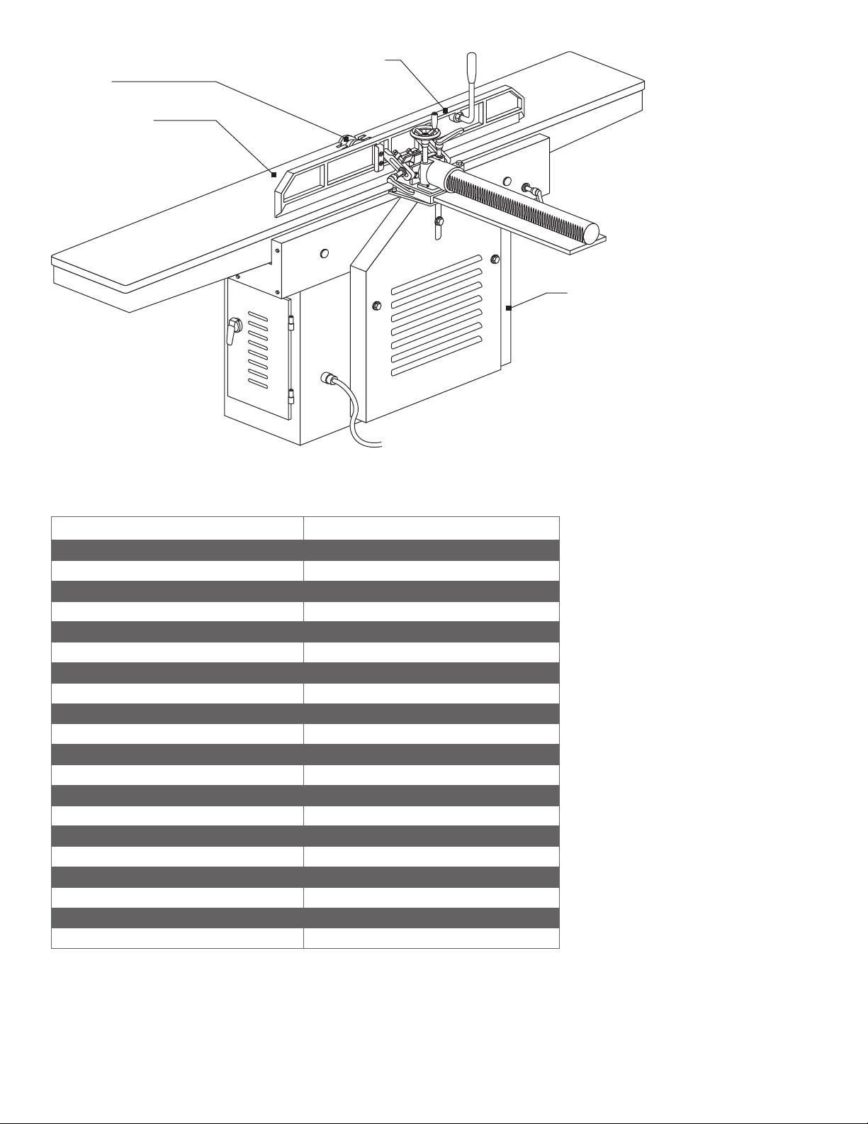
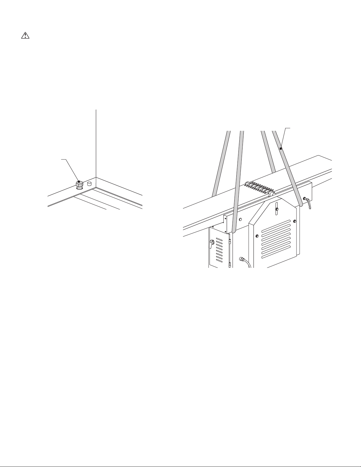
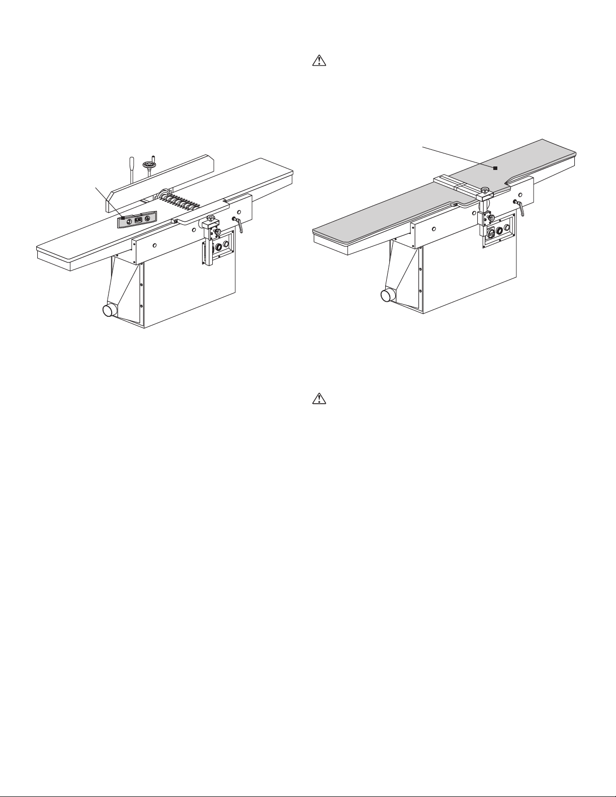
Please have your machine model and serial number available when
contacting Stiles Machinery with questions. The machine’s model
and serial number are listed on the metallic plate located on the
machine’s frame.
Information regarding the electrical system and pneumatic supply
are also listed on the metallic plate.
Machine information plate
Stiles Technical Support
616.698.6615
Stiles Parts
800.PARTS.80 (800.727.8780)
Website
www.stilesmachinery.com/ironwood/jt400
Machine Model ____________________________________________
Machine Serial Number _____________________________________
1.3 Features
• Solid construction featuring cast iron tables
• Generous 84" cutting length
• 12" cutting width with up to ¾" cutting depth
• Heavy duty steel machine base for vibration free jointing
operations
• Proven parallelogram table design
• Centralized control panel with power switch, emergency stop
switch, and power disconnect
• Quick set-up for the infeed and outfeed tables using vertical
adjustment levers
• Spiral cutterhead with carbide inserts for smooth and quiet
operation
• Heavy-duty 5-hp cutterhead motor
• Easily adjustable back fence with stops at 45, 90 and
135 degrees
1.4 Intended Use
The JT300 jointer is used to atten and straighten rough lumber,
boards, and other wood products before nishing. Face jointing
removes bowing and twists in a board that is positioned at on the
machine table. Straight-lining or edge-jointing squares a board that
is positioned on its edge on the machine table.
The machine has a 12" (305mm) cutting width, enhanced
engineering designs, and superior build construction. It offers
intelligent standard features like an interchangeable fold-away bridge
guard, helical cutting system for quiet operation, and 84" (2,135mm)
cutting length.

Ironwood JT300 | User Manual4
Cutterhead
Dust port
Back fence
Gener
ous table size
pr
ovides support for
larger workpieces
1.5 Technical Specications
Description Ironwood JT300
Max Width of Workpiece 12" (305mm)
Table Length 84" (2,135mm)
Table Width 12" (305mm)
Table Height 31½" (800mm)
Max Cutting Depth ¾" (19mm)
Fence Size 47" x 5.5" (1,195mm x 140mm)
Fence Tilt +/- 45 degrees
Positive Stops 45, 90, 135 degrees
Cutterhead Speed 5,000 rpm
Number of Knives 46
Cutterhead Insert Size 30mm x 12mm x 1.5mm
Cutting Circle 5½" (140mm)
Rabbeting Capacity ¾" (19mm)
Cutterhead Motor 5 hp
Electrical 230v / 460v (3-phase)
Amperage 13 amps (230v) / 6.5 amps (460v)
Dust Port Size 4" (100mm) port
Dust Extraction Requirements 450 cfm @ 4,500 feet/min
Shipping Dimensions 91" x 28" x 42" (2,310mm x 710mm x 1,070mm)
Shipping Weight 950 lbs. (430 kg)

Ironwood JT300 | User Manual 5
1.6 Safety Considerations
For your safety, read these instructions thoroughly before you install
and operate this machine. Always have these instructions available
at the machine for reference.
Observe all codes and regulations that apply to the installation and
operation of this machine.
Keep visitors at a safe distance from the workspace.
Keep children away from this and all machines. Childproof your work
area!
Familiarize yourself with the safety notices used in this manual.
CAUTION
If cautions are ignored, personal injury and/or machine damage
may result.
WARNING
If warnings are ignored, serious injury or death may result.
Warning Labels
This machine has warning labels attached to ensure safe operation.
These warning labels are very important and should be kept clean
and never be removed. If warning labels become damaged or lost,
contact Stiles Machinery immediately for replacements.
Label 1 Safety Rules
LABEL NO.1
WARNING
Never use the JT300 for purposes other than its intended use. Do
not modify or remove any guards or other safety features. Improper
use or modications may affect your warranty or result in serious
injury or death.
Training
This machine is intended for use by authorized, well-trained
operators only.
Do not operate this machine until you have a complete working
knowledge of the machine and have been properly trained for its
safe operation, correct adjustment, and use. All operators should
thoroughly read and understand this manual and the workings of
this machine prior to operation.
It is essential that all operators be aware of the following:
• The dangers associated with the operation of this machine
• The use of personal protective equipment for ear and eye
protection
• The proper positioning of the operator and operator’s hands
relative to the cutterhead
• The principles of machine operation
• The safe handling of the workpiece when cutting
• The safe stacking of the workpiece before and after cutting

Ironwood JT300 | User Manual6
2.0 Facility Preparation
Prior to uncrating your machine conrm that your location can
accommodate the Ironwood JT300. Follow these guidelines:
2.1 Floor
• The oor must be at and level.
• Although no special foundations are required, a concrete oor is
recommended.
• All oors must have a load-bearing strength suitable for the
machine weight of approximately 950 pounds (430 kg).
2.2 Work Space
• Provide adequate work space surrounding the machine.
• Provide proper non-glare, overhead lighting to keep the work
space well lit.
• Place the machine so that any potential kickback area is not in
line with aisles, doorways, or other work and trafc areas.
• Provide adequate dust extraction system.
The dust extraction system should have a ow rate of 4,500 feet
per minute at 450 cfm.
• Avoid exposure to any environment where vibration is present.
Standard machine clearance requirements
2'
(600mm)
4'
(1200mm)
(see footnote) (see footnote)
*
*
Machine clearance requirements*
*Actual clearance requirements may vary depending on length of
material to be cut.
2.3 Power
WARNING
A licensed electrician must connect the JT300 to the building power
source.
• Do not use extension cords.
• Be sure that the electrical current of the power source is of the
same characteristics as the 230- or 460-volt electrical system
supplied with your machine. If other machine voltage capabilities
are required, contact Stiles Machinery.
JT300
Cutterhead Motor 5 HP, 3 phase
Power 230v / 460v (3 phase)
Total Required Amperage 13 amps (230v) / 6.5 amps (460v)
• Ensure the machine is protected with an external over-current
protective device per your local electrical codes.
• Electrical equipment operating conditions:
Air temperatures between +41ºF (+5ºC) and +113ºF (+45ºC).
Relative humidity not to exceed 50% at a maximum temperature
of +113ºF (+45ºC).
• Electrical equipment is designed and protected to withstand the
effects of transportation and storage temperatures within a range
of -13ºF (-25ºC) to +131ºF (+55ºC), and for short periods of time
not exceeding 24 hours at up to +158ºF (+70ºC).
• Ensure connection to factory ground system is wired correctly
(according to IAW local electrical codes and NEC) and not
connected to any electromagnetic interference source such as
welders.

Ironwood JT300 | User Manual 7
3.0 Delivery and Installation
3.1 Receiving Your Machine
You will be contacted to arrange delivery. Your machine will be
delivered by truck to your location. If there is no loading dock,
be sure that you have informed the carrier in advance so that
they deliver using a truck with a lift gate to lower the machine to
ground level.
Before accepting the machine and signing the bill of lading from the
carrier, please inspect crating and machine condition, note potential
damage on the bill of lading, take pictures of potential damage, and
contact Stiles Machinery immediately at 616.698.7500.
The machine will arrive fully crated and secured to a pallet. Use a
hand truck or fork lift to move the machine on its pallet as close to
its nal position as possible.
If you do not intend to install the machine immediately after delivery,
store it in a protected, cool, and dry location.
The machine arrives
fully crated. Remove
and save the
paperwork attached
to crate.
3.2 Unpack the Machine
TOOLS REQUIRED:
• Hammer
• Crowbar
Unpack as follows:
Do not remove the machine from the pallet.
1. Remove and save all paperwork attached to the outside of the
crate.
2. Remove the crating, starting with the top, then remove the four
sides. Use caution to avoid personal injury and prevent damage
to the machine’s nish.
3. Remove the protective plastic from the machine, starting at the
bottom.
Remove the crating,
starting with the top,
then remove the four
sides.
Do not remove the machine from the pallet while uncrating.
Do not remove the protective paper that covers the tabletop surface.

Ironwood JT300 | User Manual8
4. Remove the plastic sleeve from the side access door handle.
The door is locked when the handle is in the vertical position.
Turn the handle to the right to unlock and open the access
door.
5. Open the access doors and check for hardware, accessories,
and tool kit that may be shipped inside the machine. If
additional accessories are ordered, they may be delivered
separately.
6. Close and lock the access doors.
3.3 Inspection
Save all containers and packing materials until you are satised
that your machine has arrived in good condition. If you discover the
machine is damaged after you’ve signed for delivery, immediately
call Stiles Customer Service at 616.698.7500.
When you are completely satised with the condition of your
equipment, you should inventory its parts.
Open and check the contents of all containers to ensure all tools,
hardware, and accessories are included. The tool kit should contain
the following items:
1. 4-piece open end wrench set
2. 4mm, 5mm, 6mm and 8mm short handle Allen wrenches
3. 5mm long-handle Allen wrench
4. Access door handle/key
5. Three (3) 5mm T-handle Allen wrenches
6. Eight (8) extra carbide inserts (30 x 12 x 1.5mm)
7. Two (2) extra angle carbide inserts (30 x 12 x 1.5mm)
8. Seven (7) extra cutterhead gibs
9. Seven (7) extra cutterhead nuts
10. Seven (7) extra cutterhead set screws
11. Four (4) leveling pads
12. Four (4) leveling bolts with nut
13. Two (2) push pads
14. Paint (2 color set)
15. User manual
3.4 Move Machine to Final Position
Be sure the site is properly prepared. Refer to section 2.0 for details.
Be sure the cabinet door is closed and locked before transporting.
TOOLS REQUIRED:
• Hand truck or fork lift
Use a hand truck or fork lift to move the machine on its pallet to its
nal location. If using a fork lift, make sure fork travel is clear of any
obstacles.
Use a crane fork
lift or hand
truck to move
the machine
on its pallet.

Ironwood JT300 | User Manual 9
3.5 Remove Machine from Pallet
CAUTION
The JT300 weighs approximately 950 pounds (430 kg). For this
procedure, we recommend using a fork lift or hand truck.
TOOLS REQUIRED:
• Adjustable wrench
• Machine-door key
When the machine has been placed at its nal location, carefully
remove the machine from the pallet.
The machine is
bolted to the pallet
for transport.
1. From inside the cabinet, remove the four bolts that secure the
machine to the pallet at the interior corners.
2. Lift the machine from the pallet by one of 3 methods:
a. Team lift
b. Slide machine onto forks of fork lift
c. With a fork lift or crane, use a hoist hook and lift strap
(suitable to lift 950 lbs.) secured to the table supports on
the machine to move and place the machine
NOTE: Never pick up a jointer by the infeed or outfeed table. This
may move the tables out of level.
3. Carefully slide the machine into nal position.
Use a lift strap to
r
emove the machine
from the pallet.
NOTE: Using a hoist hook and lift strap is the preferred method for
placing machine.

Ironwood JT300 | User Manual10
3.6 Level
TOOLS REQUIRED:
• Bubble Level
• Adjustable wrench
Use a bubble level along the length and width of the tabletop surface
to check for level. Use an adjustable wrench to adjust leveling bolts
to level machine.
Be sure to level
the machine.
3.7 Pre-Operation Cleaning
WARNING
Use proper cleaning agents and methods described below. Do not
use gasoline or other petroleum-based solvents. There is a risk of
explosion and burning if these products are used. Serious personal
injury may occur.
The machine is shipped
with protective paper on
the table assembly.
Remove and discard the protective paper from the table assembly.
Remove the rust-preventative oil that coats the machine using a soft
cloth and nonammable degreasing agent, such as Simple Green or
other citrus-based cleaners. Do not use abrasive pads.
CAUTION
Use extreme care when cleaning or working with the cutterhead.
The knives are very sharp.

Ironwood JT300 | User Manual 11
4.0 Connect to Power
• Voltage – Steady state voltage +/- 10% of nominal voltage.
• Machine needs steady voltage at all times.
WARNING
Before connecting power to the machine, make sure all screws and
fasteners are tightened, all mechanical functions work freely, and the
cutterhead turns freely.
WARNING
All connections to electrical power should be completed by a
licensed electrician.
Before connecting to a power source, conrm that the electrical
current of the power source is the same as the electrical system
supplied with your machine. Ensure the machine is protected with
an external over current protective device per your local regulating
authorities.
Machine must be properly grounded to prevent electric shock.
Never connect the yellow/green wire to a live terminal.
Once connected to power source, terminals are electried even
while the power switch is off.
Pr
oper wiring inside
terminal box
To connect power source to the machine:
1. Remove the two screws and remove the terminal box cover.
2. Remove the clear plastic insulator that covers the terminals.
3. Insert power source cables through the opening of the
terminal box.
4. Connect the three power cables to terminals L1, L2 and L3,
and the yellow/green ground wire to ground terminal.
5. Replace the clear plastic insulator and the power box cover.
Remove terminal
box covers
Connect power and
grounding wires
Remove the clear
plastic insulator
that covers the
terminals
WARNING
Always shut off power at source before removing terminal box cover.
Failure to comply with this action may result in electric shock.
CAUTION
We have covered some basic electrical requirements for the safe
installation of your machine. These requirements may not cover
all installation requirements. You must conrm that your particular
electrical conguration complies with all local codes. Ensure
compliance by checking with your local municipality and a licensed
electrician.

Ironwood JT300 | User Manual12
5.0 Safety
WARNING
Like all power equipment, there is danger associated with the
Ironwood JT300. Use caution and follow all safety instructions.
Take every precaution to protect yourself, others around you, and
the machine itself from improper use. Safety is a combination of
common sense, training, and being alert at all times while operating
your machine. If instructions, warnings, and cautions are not
followed, serious personal injury or death may occur.
EYE PROTECTION: Always wear approved safety glasses or a face
shield when operating this machine. Only use eye protection that
meets or exceeds the standards of the American National Standards
Institute (ANSI).
EAR PROTECTION: Always wear ear protection during machine
operation.
DRESS CODE: Do not wear loose clothing, neckties, jewelry, or
gloves that can get caught in moving parts. Conne long hair and
keep sleeves above the elbow.
ELECTRICAL GROUNDING: Your machine must be electrically
grounded. If a cord and plug are used, make certain the machine is
properly grounded. Follow the grounding procedure indicated by the
National Electric Code and local regulating authorities.
GUARDS: Make certain that machine guards are in place and in
good working order. The machine should never be operated without
safety guards in place.
TOOLING AND ACCESSORIES: Use only recommended
tooling and accessories. Improper tooling and accessories may
cause personal injury or damage your machine. Always run at the
correct speed and feed rate. Never force a tool or accessory to
perform a job for which it was not designed. Maintain your tools
and accessories. Knives should be sharpened and cleaned for
safe, optimal performance. Follow instructions for lubricating and
changing tooling and accessories.
POWER: Make sure that the starter is in an OFF position before
connecting power to the machine.
Make certain the machine is either unplugged or electrically
disconnected and locked out when performing all maintenance,
cleaning, or machine adjustments. Never leave the machine running
unattended. Always turn the power off and stay by the machine until
the cutterhead comes to a complete stop.
HOUSEKEEPING: Before turning on the machine, remove all extra
items on or around the machine. Keep the work area clean and free
of scrap material, sawdust and other debris to minimize the danger
of slipping. Use compressed air or a brush to remove chips or
debris. NEVER use your hands.

Ironwood JT300 | User Manual 13
6.0 Assembly
6.1 Fence Assembly
PARTS REQUIRED:
• Fence assembly
TOOLS REQUIRED:
• Wrenches
The cast iron fence assembly allows the safest and most effective
method of jointing. The fence should always be used for straight
work cutting to guide the workpiece.
The fence assembly is
attached to the pallet
for shipping.
1. Remove the two bolts that secure the fence assembly to the
pallet for shipping.
2. Attach the fence assembly to the machine body at the two
holes using the provided cap screws and lock washers.
Fence
Cap scr
ew and
lock washer
.
Hole locations
6.2 Dust Collection Manifold
PARTS REQUIRED:
• Dust collection manifold
TOOLS REQUIRED:
• Allen wrenches
Attach the dust collection
manifold over the dust
exhaust outlet.
The dust exhaust outlet is located at the left-bottom of the machine.
Attach the dust manifold using the provided Allen screws.
The outlet diameter is 4" (100mm). Use a proper diameter of dust
pipe to connect the exhaust outlet to a dust collector.
NOTE: Make sure access door inside dust manifold is closed prior to
installing dust collection manifold.

Ironwood JT300 | User Manual14
6.3 Cutterhead Guard
PARTS REQUIRED:
• Cutterhead Safety Guard
TOOLS REQUIRED:
• Allen wrenches
WARNING
For your safety, always use the cutterhead guard assembly when
using the JT300.
Fold-away guar
d
Swing-away guard
The interchangeable cutterhead guard protects your hands and
helps guide the cut. There are two styles of guards available on the
JT300 jointer:
• The fold-away guard comes standard with the JT300 jointer.
• The swing-away guard is available as an option from Stiles Parts
Dept. Call 1.800.727.8780.
Slide the spring-loaded cutterhead guard into the slot on the fold-
away bridge guard. Tighten the locking knob to secure.

Ironwood JT300 | User Manual 15
7.0 Operation and Adjustments
7.1 Machine Controls
On: Turns on
cutterhead
Machine controls are
conveniently located
on the front of the
machine
Off: Turns off
cutterhead
Power: Turns
machine power
on and off
7.2 Machine Operation
Prior to machine set-up or performing any adjustments, repair work,
or trouble shooting, it is very important to check the applicable
safety functions to ensure they are all in proper working condition.
To operate and adjust the machine, follow these steps.
WARNING
Disconnect the machine from its power source.
Step 1: Adjust V-Belt Tension
Re-check the v-belt tension weekly for the rst 3 months of
operation. There should be a small amount of deection in the belt
when pressing it midway between the pulleys. Adjust if necessary.
Check tension periodically as belts may gradually stretch over time.
1. Detach the belt cover by removing the 3 cap nuts with an Allen
wrench.
NOTE: Leave the hex nuts and at washers on the threaded rods in
place. They keep the belt cover from bending during tightening.
2. Loosen the lower hex nut on the motor base with an Allen
wrench.
3. Turn the top hex nut clockwise until proper belt tension is
achieved.
4. Retighten the lower hex nut.
5. Replace the belt cover.
The motor and belt
drive ar
e located behind
the cover on the right
side of the machine.
Step 2: Check the Cutterhead
WARNING
The knives in the cutterhead are very sharp. Handle with extreme
care when cleaning, sharpening, or replacing.
The spiral cutterhead
is equipped with a set
of 60 carbide inserts
that house the jointing
knives.
The cutterhead should be inspected before each operation. Be sure
the carbide inserts are secure and not chipped in any place. Loose
or damaged inserts may be thrown from the machine and pose
extreme danger. Chipped or missing inserts can cause imbalance in
the cutterhead and lead to bearing failure.
Also check the knives for sharpness. The knives are two sided
and can be rotated when dull. Once both sides of a knife are dull,
the carbide inserts should be replaced. To obtain replacements,
call Stiles Parts Dept. at 1.800.727.8780. Reference part
# 56-010-12005.

Ironwood JT300 | User Manual16
To remove and replace inserts, proceed as follows:
1. Loosen the knife gib by turning the Allen head screw in the
knife gib.
2. Remove the knife gib and knife.
3. Remove the remaining knives in the same manner.
4. Thoroughly clean the knife slots and knife gibs.
5. Check the screws. If they appear worn or stripped, replace
them.
6. In sequence, insert the knife and knife gib into the slot of the
cutterhead.
7. Fasten knife and gib with a spacer and Allen head screw.
8. Repeat the process until all knives are set in position and tight.
Step 3: Align and Adjust Outfeed Table
CAUTION
The proper outfeed table height is preset at the factory. To ensure
the setting did not change during shipping, check outfeed table
height before you use the machine for the rst time. Re-check
periodically.
For accurate work in most jointing operations, the outfeed table
must be exactly level with the knives at their highest point of
revolution.
If the outfeed table is too high, the nished surface of the workpiece
will be curved.
Work Piece
Infeed Table
WRONG
Outfeed Ta ble
Cutter
Head
If the outfeed table is too low, the work will be gouged or sniped at
the end of the cut.
Work Piece
Infeed Table
Outfeed Ta ble
Cutter
Head
WRONG
To properly align the cutterhead with the outfeed table:
1. Place a straight edge on the outfeed table and over a knife
tip on the cutterhead. Be careful not to damage the carbide
inserts.
Verify blade height
with straight edge.
2. Carefully turn the cutterhead by hand.
• If a knife tip makes contact with the straight edge, but
the straight edge does not move, the outfeed table is set
properly.
• If a knife tip does not touch the straight edge, the outfeed
table is too high.
• If the straight edge lifts slightly when knife makes contact,
the table is set too low.
To adjust the outfeed table height:
1. Loosen the table lock lever.
2. Move the adjustment handle up or down.
3. Tighten the table lock lever.
As a nal check, run a piece of wood slowly over the knives for 6 to
8 inches. The wood should rest rmly on both tables with no open
space under the nished cut.
Infeed Table
Outfeed Ta ble
Cutter
Head
Work Piece
CORRECT

Ironwood JT300 | User Manual 17
For more precise adjustment, use a dial indicator. Place the gauge
on the outfeed table and adjust the dial to “0” on the indicator.
Outfeed Table
Place the dial indicator on the outfeed table with the at indicator
point touching a knife edge.
Infeed Table
Outfeed Table
Cutter
Head
Adjust the table height. When the pointer reaches “0”, the knife edge
and outfeed table are even.
CAUTION
After the outfeed table has been set at the correct height, it should
not be changed except for special operations or after replacing
knives.
Step 4: Align and Adjust Infeed Table
The depth of cut is determined by the distance between the infeed
table surface and the knife edge at its highest point on the cutting
circle.
For an accurate depth of cut, make sure the gauge on the side of
the table reads “0” when the table surface is exactly level with the
knives at their highest point of revolution.
Conrm table height.
To check table height:
1. Place a straight edge on the infeed table and over a knife tip on
the cutterhead. Be careful not to damage the carbide inserts.
Verify blade height
with straight edge.
2. Carefully turn the cutterhead by hand.
• If a knife tip makes contact with the straight edge, but the
straight edge does not move, the table is set properly.
• If a knife tip does not touch the straight edge, the table is
too high.
• If the straight edge lifts slightly when the knife makes
contact, the table is set too low.
To adjust the infeed table height:
1. Loosen the table lock lever.
2. Move the adjustment handle up or down.
3. Tighten the table lock lever.
When the table surface is even with the knife edges, make sure the
red gauge indicator is at “0”. If it is not:
1. Loosen the indicator with a screwdriver.
2. Adjust the indicator to “0”.
3. Retighten the screw.
Step 5: Set Depth of Cut
1. Loosen the infeed table lock handle.
2. Move table adjustment arm to raise or lower the infeed table.
The gauge indicates the distance that the table has been raised
or lowered from the “0” point.
3. Tighten the table lock handle.

Ironwood JT300 | User Manual18
Step 6: Adjust Fence Assembly
Using the fence is the safest and most accurate method of jointing,
and should always be used when work permits.
The fence tilts forward and backward to 45 degrees. It has a
90-degree stop, 135-degree stop, and 45-degree stop.
Lock handle
and tilt handle.
To tilt the fence forward:
1. Loosen the lock handle.
2. Use the tilt handle to tilt the fence forward. Lift up slightly on the
fence while tilting to prevent scratching of the table surface.
3. Tighten the lock handle.
To tilt the fence backward:
1. Loosen the lock handle.
2. Pivot the stop block out of the way.
3. Use the tilt handle to tilt the fence forward. Lift up slightly on the
fence while tilting to prevent scratching of the table surface.
4. Tighten the lock handle.
To move the fence forward or back:
1. Loosen the lock handle.
2. Rotate the handwheel counterclockwise to move the fence
forward. Rotate the handwheel clockwise to move the fence
back.
3. Tighten the lock handle.
To check and adjust the 90-degree stop:
1. Loosen the lock handle.
2. Tilt the fence until the stop screw contacts the stop block.
3. Place a square or machinist’s protractor (not provided) on the
table and against the fence surface.
4. If the angle is not 90 degrees, loosen the hex nut on the stop
screw.
5. Turn the stop screw until the fence is ush with the square.
6. Tighten the hex nut.
7. Tighten the lock handle.
To check and adjust the 45-degree stop:
1. Loosen the lock handle.
2. Tilt the fence until it contacts the 45-degree stop.
3. Place a square or machinist’s protractor set (not provided) at
45 degrees on the table and against the fence surface.
4. If the angle is not 45 degrees, loosen the hex nut on the stop
screw.
5. Turn the stop screw until the fence is ush with the protractor.
6. Tighten the hex nut.
7. Tighten the lock handle.
Step 7: Adjust Cutter Guard Tension (For Swing-Away Guard Only)
Set the cutter guard tension so that:
• The guard conceals the unused part of the cutterhead
• After the workpiece clears the cutterhead, the guard swings
back to contact the fence
To adjust:
1. Loosen the tension knob.
2. Push the knob to the right to increase tension; turn to the left to
decrease tension.
3. Tighten the knob.
Step 8: Feed the Workpiece Through the Jointer
WARNING
Do not attempt to operate the machine if you are not completely
familiar with its operation. Obtain immediate advice from a
supervisor, instructor, or other qualied personnel.
Use of this machine requires that you give your work your undivided
attention, and careless acts or not paying close attention to work
being performed may result in serious injury to yourself and/or
others. Never operate this or any machine under the inuence of
drugs, alcohol, or any medication that may impair judgment.
Dust created by manufacturing activities may be harmful to your
health. Your risks from exposure may vary. Always work in a well-
ventilated area and wear safety approved, protective dust masks
specically designed to lter out microscopic particles. Utilize wood
dust collection systems appropriate to your machine type.
Avoid Kickback
It is very important that each workpiece be carefully inspected for
stock condition and grain orientation before running through the
machine. “Pull-out” and the dangerous kicked back material can
result when the workpiece has knots, holes, or foreign materials
such as nails. Kickback can also occur when the material is fed
against the grain on the cutterhead.

Ironwood JT300 | User Manual 19
CAUTION
During certain applications, it may be necessary to plane against the
grain. This application requires that the operator use a shallow depth
of cut and a slower feed rate.
CAUTION
If you are inexperienced at jointing, use scrap pieces of lumber to
become familiar with the machine and its operation before doing
normal work.
WARNING
Do not operate this machine with the safety guard removed.
Before starting the machine, inspect the machine to ensure it is free
of all debris.
Inspect area around cutterhead to ensure the cutterhead is free of
debris.
Never start the machine with the workpiece in contact with the
cutterhead.
Make sure the workpiece is free of nails, loose knots, and other
defects that could cause personal injury or damage the knives.
Remove wood chips and shavings only with the power off.
Stand to the side of the workpiece when feeding it through the
jointer to avoid potential injury from kickback and loose chips.
Keep your hands at least 3" (7.6cm) away from the cutterhead area.
Never pass your hands directly over the cutterhead.
Do not perform jointing operations on material shorter than
8" (20cm), narrower than ¾" (2mm), or less than ¼" (.65mm) thick.
To stop a workpiece before it is entirely fed through the machine,
press the Off button. Wait until the cutterhead has completely
stopped before removing material. Attempted removal while
cutterhead is turning may cause kickback.
To feed a workpiece:
1. Turn the red power switch on the control panel to on.
2. Press the green on button to turn on the cutterhead.
3. Feed the workpiece through the machine.
NOTE: If only workpieces of the same dimensions are run through
the jointer, the operator may want to occasionally adjust the fence
forward or backward to prevent wear on only one area of the knives.
Hand Placement When Feeding a Workpiece
At the start of the cut, your left hand holds the workpiece rmly
against the infeed table and fence while your right hand pushes the
workpiece toward the knives.
After the cut is under way, your left hand presses down on the new
wood surface so it rests rmly on the outfeed table and maintains
at contact with the fence.
Before your right hand reaches the cutterhead area, move it to the
workpiece on the outfeed table. NEVER PASS HANDS DIRECTLY
OVER THE CUTTERHEAD.
NOTE: Push blocks are recommended for additional safety.
Proper Grain Direction
Avoid feeding workpieces into the jointer against the grain to prevent
chipped and splintered edges. Feed with the grain to obtain a
smooth surface.
Against Grain
Infeed Table
Outfeed Ta ble
Cutter
Head
WRONG
With Grain
Infeed Table
Outfeed Ta ble
Cutter
Head
CORRECT

Ironwood JT300 | User Manual20
7.3 Types of Cuts
Edge Jointing
Depth of cut should be the minimum required to obtain a straight
edge. Do not make cuts deeper than 1/8" (3.2mm) in a single
pass. Hold the best face of the workpiece rmly against the fence
throughout the feed.
Surfacing
Depth of cut should be the minimum required to obtain a straight
edge. Do not cut more than 1/16" (1.5mm) per pass to allow control
of the workpiece. Always use a hold-down device or push block
when surfacing short stock or stock less than 3" (7.6cm) thick.
Rabbeting
The width and thickness of your workpiece is dependent upon
your preferred width and length of the rabbet (a groove cut along
the edge of a workpiece). Never rabbet a workpiece less than
12" (30.5cm) long.
Rabbeting
WARNING
Rabbet cuts require removal of the cutterhead guard. Always
use extreme caution while rabbeting. Keep hands clear of the
cutterhead. When rabbeting is complete, immediately replace the
guard.
Jointing Warped Pieces
If the workpiece is deformed or warped, make shallow cuts with
multiple passes until the surface is at. Do not force the workpiece
down against the table; excessive pressure prevents the jointer from
attening the workpiece so it remains warped, curved, or cupped.
Jointing Short or Thin Workpieces
Always use a push block to prevent injury when jointing short or thin
workpieces.
Beveling
Lock the fence at the required angle, and keep the workpiece rmly
against the fence and tables. Several passes may be necessary to
remove enough material and achieve the desired result.
Taper Cutting
Lower the forward end of the workpiece onto the outfeed table
instead of starting the workpiece on the infeed table. Do this very
carefully, as the piece will span the cutterhead, which will begin
cutting at the point of contact with the workpiece. Firmly hold the
workpiece when placing it on the jointer to prevent kickback. Push
the workpiece forward as in ordinary jointing. The effect is to plane
off all the stock in front of the knives to increase depth, leaving a
tapered surface. The taper can be determined by the amount of
stock removal and the number of passes performed.
To remove any ridge left by the knives when starting the taper,
make a very light cut using the regular jointing method, with the
infeed table raised to its usual position. Practice is required for this
operation, and the beginner is advised to make trial cuts on waste
material.
Use extra precautions when performing such procedures.
Table of contents
Other Ironwood Power Tools manuals