iRZ TU31 User manual

Operation Manual
3G modem iRZ TU31

2
Table of Contents
1.Introduction............................................................................................................................. 4
1.1.About this Document ............................................................................................................................4
1.2.Service Information...............................................................................................................................4
1.3.Safety Precautions ...............................................................................................................................4
2.Overview.................................................................................................................................. 5
2.1.Purpose ................................................................................................................................................5
2.2.Package Contents ................................................................................................................................5
2.3.Specifications........................................................................................................................................5
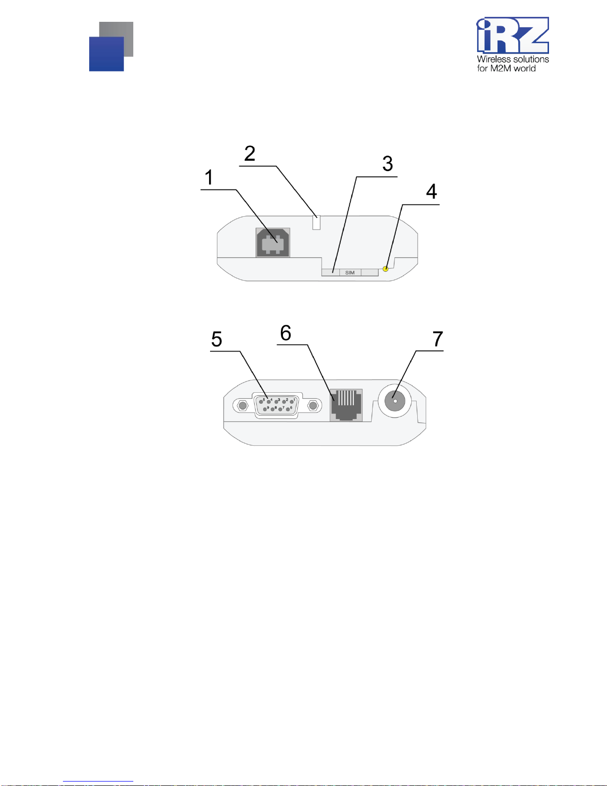
2.4.Device View..........................................................................................................................................7
2.5.Interfaces..............................................................................................................................................8
2.5.1. Interface connector (RS232).........................................................................................................8
2.5.2. Power Connector..........................................................................................................................9
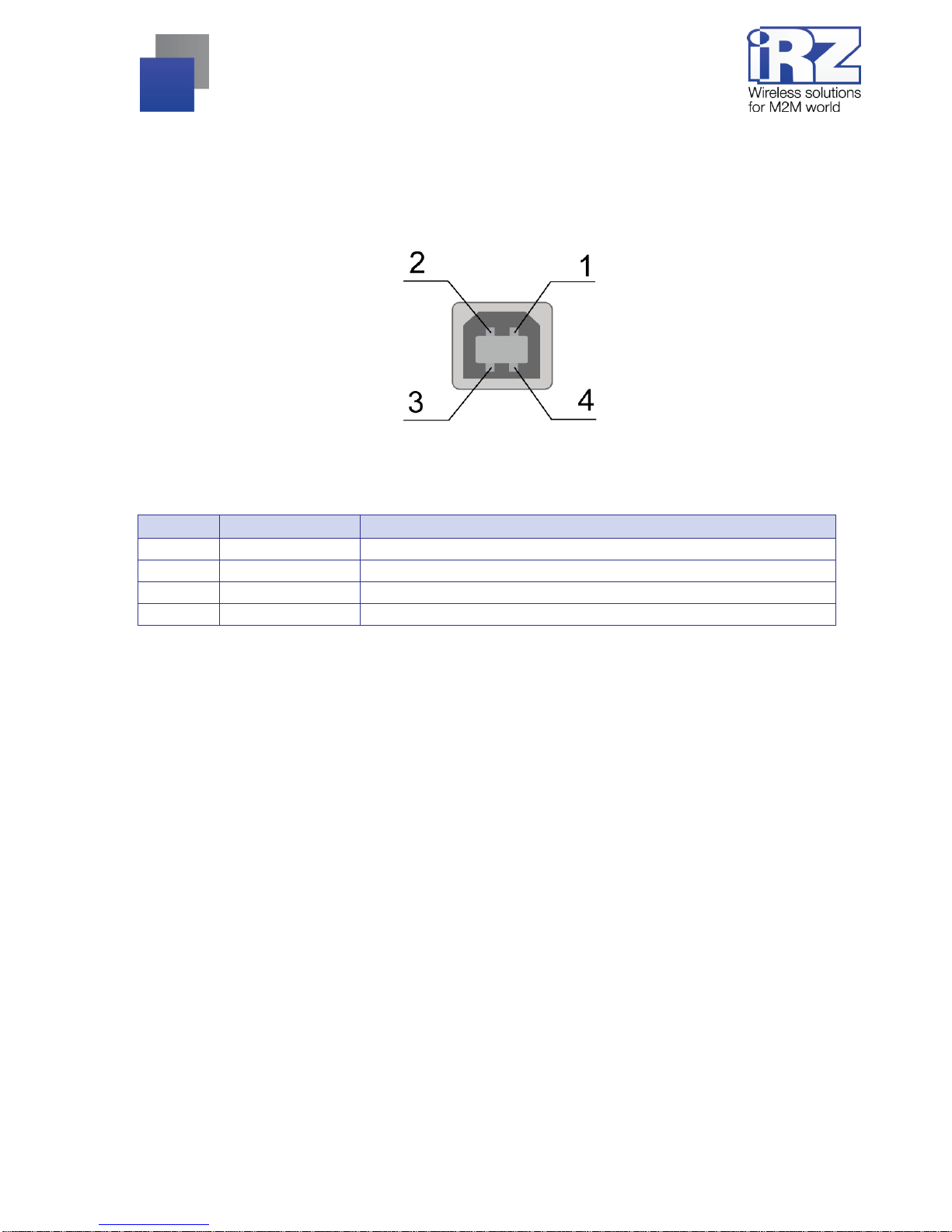
2.5.3. USB connector............................................................................................................................10
2.6.Modem Status Indicators....................................................................................................................11
3.Connection, configuration and control................................................................................ 12
3.1.Connecting, operating mode ..............................................................................................................12
3.2.Control, Reset and Power Off.............................................................................................................13
3.3.Menu mode.........................................................................................................................................13
4.Emergencies.......................................................................................................................... 17
4.1.Emergency 1 (incorrect input power supply)......................................................................................17
4.2.Alarm 2 (incorrect module power supply)...........................................................................................17
4.3.Emergency 3 (GSM module failed to run)..........................................................................................17
5.Support.................................................................................................................................. 18

3
Tables:
Table 2.5.1 Interface connector's pin assignments.................................................................................. 8
Table 2.5.2 Power connector pin assignments........................................................................................ 9
Table 2.5.3 USB connector pin assignments........................................................................................ 10
Table 2.6.1 Operation mode indication (green LED).............................................................................. 11
Table 2.6.2 Fault condition indication (red LED).................................................................................... 11
Figures:
Fig. 2.1 Front panel ............................................................................................................................. 7
Fig. 2.2 Back panel.............................................................................................................................. 7
Fig. 2.5.1 Interface connector ............................................................................................................... 8
Fig. 2.5.2 Power Connector.................................................................................................................. 9
Fig. 2.5.3 USB connector................................................................................................................... 10

4
1. Introduction
1.1. About this Document
The operation manual is intended for skilled PC users and provides the description and operating
procedure of the iRZ TU31 3G modem.
1.2. Service Information
Document version
Issue Date
2.1
18/02/2016
Prepared by:
V. Golovin
Checked by:
B. Makatrinskiy
1.3. Safety Precautions
Restrictions on the router use near other electronic devices:
Power off the modem in medical centres and keep it away from medical equipment (cardiac
pacemakers, hearing aids). Medical equipment may be susceptible to any form of radio interference. In
such areas the modem can transmit signals that could interfere with this equipment.
Power off the modem in an aircraft. Take measures against accidental activation.
Power off the modem near gas stations, enterprises of chemical industry, in areas where blasting
operations are in progress. The modem can interfere with operation of technical devices.
At close range the modem can interfere with television and radioreceiver operation.
To ensure safe operation, follow the recommendations:
Do not expose the modem to aggressive influences (high temperatures, corrosive chemicals, dust,
water, etc.).
Protect the modem from impacts, falls and excessive vibration.
Do not attempt to disassemble or modify the modem. Such actions will void the warranty.
Note: Use the device in compliance with the operating instructions. Damages caused by improper use and
storage of the device are not covered by the warranty.

5
2. Overview
2.1. Purpose
The iRZ TU31 3G modem is an industrial GSM modem designed for high-bandwith data and text
messages transmission over GSM channel. It is well-designed for mobile Internet access, as well as for
industrial applications: telemetry, wireless data collection from sensors, remote surveillance and signalling.
The modem is implemented with function of unconditional reset upon set time intervals. The modem is
controlled via standard AT commands as well as some control commands of its own. It is fitted with LED lights
to indicate connection status and possible faults.
2.2. Package Contents
iRZ TU31 3G modem set:
TU31 terminal;
original package.
2.3. Specifications
General characteristics:
Frequency bands:
900/1800 MHz for GSM/GPRS/EDGE;
900/2100 MHz for HSPA+/UMTS;
Output power:
33 dBm (Class 4) for EGSM900;
30 dBm (Class 1) for GSM1800;
27 dBm (Class E2) for GSM900 8-PSK;
26 dBm (Class E2) for GSM1800 8-PSK;
24 dBm (Class 3) for UMTS2100, WCDMA FDD BdI;
24 dBm (Class 3) for UMTS900, WCDMA FDD BdVIII.
Standards and data transmission rates:
HSPA+ download —7,2 Mbps, upload —5,7 Mbps;
UMTS PS download —384 kbps, upload —384 kbps;
UMTS CS download —64 kbps, upload —64 kbps;
EDGE Class 12, download —236.8 kbps, upload —236,8 kbps;
GPRS Class 12, download —85,6 kbps, upload —42,8 kbps;
MS Class B;
USSD;
SMS: MT, MO, Text and PDU.

6
Power Supply
Power voltage –9 to 30V
When powered through USB, 5V
current consumption:
At a supply voltage of +12V –max 400 mA
At a supply voltage of +24V –max 200 mA
Physical Specifications
Dimensions –max 69x75x26 mm;
weight: max 125 grams;
Operating temperature: -30°С to +60°С;
Storage temperature: -40°С to +85°С.
Interfaces and Connectors:
USB connector (type B) –data cable connection, USB 2.0 interface, modem power supply;
Interface connector DB9-FF —connection of communication cable and RS232 interface;
FME-M antenna connector —connection of the GSM antenna;
TJ6-6P6C power connector —modem power, reset signal.

7
2.4. Device View
The TU31 modem is a compact-size device encased in a plastic housing. The device general view is given
in Fig. 2.1 and Fig. 2.2.
Fig. 2.1 Front panel
Fig. 2.2 Back panel
The numbers in the figures illustrate:
1. USB connector (B type) –connection of communication cable;
2. LED status (green) and error (red) indicators;
3. SIM card tray;
4. Eject button for SIM card tray;
5. Interface connector DB9-FF, connections of communication cable;
6. Power connector TJ6-6P6C, power connection;
7. Antenna connector FME-M, connections of a GSM antenna.

8
2.5. Interfaces
2.5.1. Interface connector (RS232)
The DB9 connector is designed for connection to a control device via RS232 interface. Factory settings:
connection speed of 115200 bps, 8-N-1. The view of the connector is shown in Fig. 2.5.1:
Fig. 2.5.1 Interface connector
Table 2.5.1 Interface connector's pin assignments
Pin
Signal
Direction
Function
1
DCD
Modem-PC
Carrier Detect
2
RXD
Modem-PC
Receive Data
3
TXD
PC-Modem
Transmit Data
4
DTR
PC-Modem
Data Terminal Ready
5
GND
Ground
System Housing
6
Not used
7
RTS
PC-Modem
Request To Send
8
CTS
Modem-PC
Clear To Send
9
RI
Modem-PC
Ring Indicator
Pin assignments match serial interface with V.24 protocol.
Cable length must not exceed 1,8 m. It is not recommended to use transmission speed above 115200 bps.
Note: The RS232 (COM port) standard does not allow hot plugging.
To prevent damage to the modem's COM port, be sure to connect and disconnect devices after at least 5
seconds upon powering them off.

9
2.5.2. Power Connector
Main designation of TJ6-6P6C is connecting the modem's power supply. The modem is also fitted with
emergency reset pin. The view of the connector is shown in Fig. 2.5.2.
Fig. 2.5.2 Power Connector
Table 2.5.2 Power connector pin assignments
Pin
Signal
Function
1
+Vin
Positive terminal of constant power supply voltage. Protected by a fuse and
overvoltage (at input power supply over 30V) and reverse polarity protection
circuit. Range of voltage: 9 V to 30 V
2
Not used
3
RESET
Modem reset –send positive impulse (10 to 20 V) with length above 50 ms
4
Not used
5
Not used
6
GND
System Housing

10
2.5.3. USB connector
USB connector (B type) is used for connection to managing device via USB 2.0 interface. The view of the
connector is shown in Fig. 2.5.3:
Fig. 2.5.3 USB connector
Table 2.5.3 USB connector pin assignments
Pin
Signal
Function
1
+5V
Modem power, consumption no more than 500 mA
2
D−
Transmit Data
3
D+
Transmit Data
4
GND
System Housing

11
2.6. Modem Status Indicators
Two LED indicators are used for displaying operation mode status or emergency situation. Indication can
be controlled via AT command "AT^SLED". By default, the value is AT^SLED=2,50. LED indication modes for
displaying operation modes are given in Table 2.6.1.
Table 2.6.1 Operation mode indication (green LED)
Status display mode
Schematic LED signals
representation
Operating mode
Off
○
The modem is switched off or at fault condition;
power-saving mode; "ALARM" mode
500 ms on / 500 ms off
●●●●●○○○○○
The modem is not registered to the network
50 ms on / 3990 ms off
●○○○○○○○○○○○○○...○
The modem is registered on the network
50 ms on / 1990 ms off
●○○○○○○...○
GPRS connection established / Data
transmission in progress (GPRS)
250 ms on / 250 ms off
●●●○○○
Programming mode, menu mode
50 ms on / 990 ms off
●○○...○
Voice call, CSD
Table 2.6.2 Fault condition indication (red LED)
Status display mode
Schematic LED signals
representation
Fault description
Continuously lit
●
Wrong input voltage
0,25 s on / 0,25 s off /
0,25 s on / 1 s off
●○●○○○○
GSM module failed to start
0.5 s on / 0.5 s off
●○
Wrong module power
Emergency situations are described in section 4 of this document.

12
3. Connection, configuration and control
3.1. Connecting, operating mode
All installation operations are to be carried out by a qualified specialist familiar with the installation guide.
Before supplying power, install the SIM card into the modem. The following actions are required:
Remove a SIM card tray pressing the eject button (see Fig. 2.1);
Insert a SIM card into the SIM card tray;
Insert SIM tray into the modem.
Do not apply much force when inserting a SIM card. Connect a GSM antenna and a switching cable.
Modem is fitted with USB interface for connecting to the controlling device: RS232 and USB. Control can be
carried out via both interfaces simultaneously.
Turn the modem's power supply on via power connector (see Fig. 2.5.2). When operating via USB
interface, simply connecting USB cable is enough. After power supply is connected, the modem will start. This
will be indicated by green LED (see Table 2.6.1). If PIN code is switched off, registration within network will
occur automatically.
Note: A GSM antenna, switching cables and a power supply unit are not included.
When operating via USB interface, it is required to install a driver on your PC. You can download the driver
from www.radiofid.ru and www.irz.net websites. After installation of the driver, several new devices are to be
displayed in the Windows Device Manager.
Cinterion EHx USB Modem in the Modems section.
Several Cinterion EHx USB COM Port ports in the Ports section.
Cinterion EHx USB COM Port 3 –port for displaying service menu.

13
3.2. Control, Reset and Power Off
The connection of iRZ TU31 modem's to Internet and its configuration via PC is carried out in the same way
as with a standard modem. It is recommended to set module speed for RS232 interface to 115200 bps and
select modem's model in the connection. Standard speed is 33600 bps. For industrial applications modem
control is carried out via standard AT commands. You can download the description of AT commands from
www.radiofid.ru and www.irz.net websites.
You can reboot the modem in the following ways:
by 8 switches of DTR COM port to passive state (DTR < -2V), pulse length and pauses between pulses
must lay within 100-500 ms range;
by sending a positive pulse (10 to 20 V) no shorter than 50 ms to power connector's pin No.4 (see
section 2.5.2);
Reboot after a set period of time (WD interval, switched off by default). Configured in the Menu mode;
by AT command “AT+CFUN=1,1”;
by temporary powering off.
The modem can be switched off by:
by AT command “AT^SMSO”.
by powering off.
Switching to power saving mode is done with AT command “AT+CFUN”. For more details, see description
of AT commands for GSM module.
3.3. Menu mode
Menu mode's funtion is to change the modem parameters and access statistics. Switching to Menu mode is
possible from Operation mode. To switch to Menu mode, eject the SIM tray. Before accessing the menu mode
connect the modem to the computer (Cinterion EHx USB Com Port3), run Hyper Terminal or a similar program
to communicate with the modem.
The modem will go into the menu mode:
Menu mode:
Variant XX
<P1> View statistic
<P2> WD interval = OFF
<PC> Power control
<PR> Clear statistic
Variant XX –firmware version.

14
The <P…> characters indicate the control commands. To run a command, press the Enter key. If the
command is incorrect, the ERROR message is displayed. The command input is case-insensitive.
“P1” command will switch to statistics mode:
Statistics:
Power_Modem = XXX
Bad_Power_Modem = XXX
Power_Module = XXX
Bad_Power_Module = XXX
Reset = XXX
where:
Power_Modem –the number of the modem actuations;
Bad_Power_Modem –the number of power deviations of the modem;
Power_Module –the number of times power GSM module's switched on;
Bad_Power_Modem –the number of power deviations of the GSM module;
Reset –the number of resets.
After displaying statistics, the modem will switch to Main Menu
“P2” command will switch to WD mode:
WD interwal,hh (WD OFF: hh=0, max: hh=255)
<Q> Quit
WD interval =

15
This sets the time interval for module restart. For changing this interval, enter number from 0 to 255 and
press "Enter" key. Interval is set in hours. To disable this function enter 0. Please note, that the modem will be
forced to restart after interval expiration. If entry is incorrect, "ERROR" message will be displayed and you will
be redirected to WD menu again. If entry is correct or after entering “Q” command, you will be redirected to
Main menu.
Entering the “PC” command allows to review the control voltages of the module (measurement precision
5%):
If the modem is powered via power connector, then
POWER Uin: 12.0 Umd: 4.0 V
If the modem is powered via USB, then
POWER Uin: USB
Umd: 4.0 V
where Uin —input voltage (V), Umd —GSM module voltage (V).
After displaying data, the modem will switch to Main Menu
“PR” command will switch to statistics reset menu:
Clear statistic?
<Yes> Yes
<Q> Quit
Reset the accumulated statistics by "YES" command. If entry is incorrect, "ERROR" message will be
displayed and you will be redirected to Statistic menu again. If entry is correct or after entering <Q> command,
you will be redirected to Main menu.
“PG” command will switch to modem operation mode menu:
Work mode ( 0-OFF, 1-3G pref, 2-2G pref, 3-3G only, 4-2G only )
<Q> Quit
Work mode =
Operation mode of the modem is set. To change the modem's operation mode enter:
0 –OFF, operation mode selection is enabled;
1 –3G pref, priority is given to working with 3G networks;
2 –2G pref, priority is given to working with 2G networks;
3 –3G only, working with 3G networks only;

16
4 –2G only, working with 3G networks only (must be set for CSD call).
To run a command, press the Enter key. If entry is incorrect, "ERROR" message will be displayed and you
will be modems' operation mode menu again. If entry is correct or after entering <Q> command, you will be
redirected to Main menu.
Entering “M” command switches to back Main menu. You can exit the Menu mode by inserting the SIM
tray; the modem will switch to Operation mode. Close the port before inserting the SIM tray

17
4. Emergencies
To facilitate the use of the modem, tracking and display of emergencies are provided.
4.1. Emergency 1 (incorrect input power supply)
Emergency 1 occurs when the controlling internal voltage deviates from the permissible value. The modem
stops operating: and switches off GSM module power supply. Emergency is indicated by continuously lit red
LED. The recovery is possible only when the controlling internal voltage is re-established.
4.2. Alarm 2 (incorrect module power supply)
Emergency 2 occurs when GSM module's' power supply deviates from the permissible value. The
modem stops operating and switches off GSM module power supply. A red LED signals that the emergency
has occurred (0.5s on / 0.5s off). The recovery is possible only if the module power supply is re-established
within 10 seconds after the emergency has occurred. If within 10 seconds the module power supply remains
incorrect (with a correct input power supply), the modem goes into the waiting mode meaning that the modem’s
power supply is turned off, the emergency indication is preserved. The waiting mode can be terminated only
after the power is completely disconnected.
4.3. Emergency 3 (GSM module failed to run)
Emergency 3 occurs if the GSM module does not turn on or is absent. A red LED signal
(0.25s on / 0.25s off / 0.25s on / 1s off) turns on after the modem precisely detects the emergency situation
(~15 sec). The recovery is possible only after a successful launch of the GSM module. After 10 unsuccessful
attempts to launch the module, the modem goes into the waiting mode. The modem’s power supply is turned
off, the emergency indication is preserved. The waiting mode can be terminated only after the power is
completely disconnected.
In case of repeated emergency, the modem should be serviced.

18
5. Support
To get updated documents and software updates, please use the following contacts:
St. Petersburg
The company’s website:
www.radiofid.ru
Phone number in St. Petersburg:
+7 (812) 318 18 19
E-mail:
Moscow
The company’s website:
www.digitalangel.ru
Phone number in Moscow:
+7 (495) 974 74 22
E-mail:
Our specialists are always ready to answer your questions, assist in installation, configuration and resolve
difficulties with using the equipment.
This manual suits for next models
1
Table of contents
Other iRZ Modem manuals
Popular Modem manuals by other brands

Telenetics
Telenetics Global Carrier 56 user guide

ATC
ATC 277SM user manual

Huawei
Huawei MT886 user guide

NETGEAR
NETGEAR DGFV338 - ProSafe Wireless ADSL Modem VPN Firewall... Reference manual

US Robotics
US Robotics 56K PCI FAXMODEM - QUICK REV 1 Quick installation guide

Yaesu
Yaesu FTM-400XDR operating manual