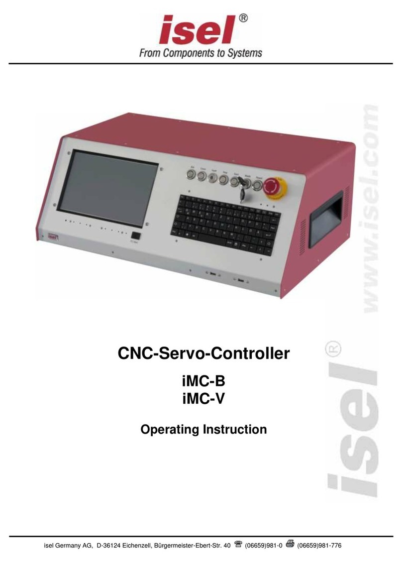
Isel iMC-S8 User manual

isel Germany AG, D-36124 Eichenzell, Bürgermeister-Ebert-Str. 40 (06659)981-0 (06659)981-776
4-axis-controller
iMC-S8
Operating Instruction

isel Germany AG, D-36124 Eichenzell, Bürgermeister-Ebert-Str. 40 (06659)981-0 (06659)981-776
About this operating instruction
Used shortcuts
MRL
machine directive 2006/42/EC
ERL
EMC directive 2014/30/EC
NRL
low voltage directive 2014/35/EC
Used symbols
You will find different symbols in this manual that signalizes important information/
facts and danger.
Warning!
This symbol indicates dangers that cause damages for person’s health,
physical injury or death.
Warning! Dangerous voltage!
Warning of danger from electricity. Ignoring can lead to serious injury or
death.
Attention!
This Symbol indicates important notes. Ignoring this symbol leads to
damages and malfunctions of the machinery
Information:
This symbol indicates important information and notes.
Observe the safety instructions
Before you take the 4-axis-controller iMC-S8 in operation, working
with the controller or make additions or changes to the wiring of
the, make sure to read carefully the safety instructions in this
manual. (Chapter 1.2 Safety instructions).

isel Germany AG, D-36124 Eichenzell, Bürgermeister-Ebert-Str. 40 (06659)981-0 (06659)981-776
All information, technical data and dimensions contained in this booklet correspond to
the technical state at the moment of publication. However, possible misprints or
mistakes cannot be ruled out. We will appreciate all suggestions for improvement and
error notes.
We would like to point out that all used software and hardware names of the respective
companies generally are subject to protection by brand, trademark and patent law.
All rights reserved. It is prohibited to process, duplicate or reproduce this booklet
partially or on the whole in any form (print, copy, or other procedure) without written
permission of isel Germany AG.
This booklet has been translated from the original German version into English
language. It does not lay claim to completeness nor flawlessness. In case of doubt the
German original has validity.
isel controllers are concurrent with CE norms and marked accordingly.
Commissioning of all other parts or components, for which CE safety
regulations apply, is prohibited until all respective requests are met.
isel Germany AG as the manufacturer cannot take over guarantee if you
change the controller in any way.
The EMC test is valid only for the controller’s original configuration ex
works, i.e. the delivery state.
Manufacturer: isel Germany AG
Bürgermeister-Ebert-Straße 40
D-36124 Eichenzell
Tel.: (06659) 981-0
Fax: (06659) 981-776
http://www.isel.com
Item-No.: 970395 BE001
(Translation of operation instruction in German language)
Revisions
Date of
change
Reason for change
Changed by
c
13/09/2016
Declaration of Conformity
RL
b
08/06/2015
Current setting MD24
RL
a
06/01/2015
Serial number
RL
07/2014
First print
Technical changes reserved.
Latest operating instructions and manuals for download, visit:
www.isel.com

isel Germany AG, D-36124 Eichenzell, Bürgermeister-Ebert-Str. 40 (06659)981-0 (06659)981-776
Table of contents
1Introduction.......................................................................................................5
1.1 Intended use........................................................................................................5
1.2 Safety instructions................................................................................................6
2Scope of delivery..............................................................................................8
3Technical data...................................................................................................9
4iMC-S8 hardware description ........................................................................11
4.1 front side............................................................................................................11
4.2 Back side...........................................................................................................13
4.2.1 Using inverter-case FCC-750...................................................................................... 20
4.3 Assembly iMC-S8 ..............................................................................................21
4.3.1 DIP-switch settings..................................................................................................... 22
5Operation modes and operation....................................................................25
5.1 Controller preparation........................................................................................25
5.2 CNC-mode.........................................................................................................26
5.3 Initial Operation and user programming in CNC-mode......................................27
5.3.1 Install programming software PALPC.exe................................................................... 27
5.3.2 PALPC- operation....................................................................................................... 28
5.4 DNC- mode........................................................................................................30
5.5 Initial operation und user programming in DNC-mode.......................................31
6EC - Declaration of Conformity......................................................................34
7Bibliography....................................................................................................35
8Index ................................................................................................................35

iMC-S8 –operating instruction
page - 5
1 Introduction
The stepper-motor-controller iMC-S8 is a freely programmable compact control up to
four linear or rotational units with 2-phase stepper motors. The controller integrates
maximum four motor power amplifiers with step/direction interface, a processor core
with flash memory to interpret the user programs and generating step/direction signals
for the power amplifiers, power supply units, security circuit module and a table
housing with net input filter and control elements.
1.1 Intended use
The processors operating system (firmware) provides following operation modes:
DNC-mode:
The controller is permanent connected with a PC/laptop via serial interface.
CNC-mode:
The controller works „Stand Alone“ after a user program is downloaded to the
processors flash memory.
The controller is able to drive stepper-motors in micro stepping mode. The power
amplifiers generates up to 128 micro-steps per full-step. This allows a smoothly run of
the connected motors. An automatic current reduction reduces the power loss in the
amplifier and motor.
The peak current amounts 7,8A and is adjustable via DIP-switches.
With the impulse input it’s possible to control the most important functions (start,
stop). Thereby it’s also possible to connect an external control console or a higher
ranked control (e.g. PLC).
All axis of the controller have to be used only with the compatible motor type.
Please read this operation instruction manual carefully before first use of the controller
therewith you can:
•Work safely, fast and effective
•Keep away danger from persons
•Use all the power and features of the controller.

iMC-S8 –operating instruction
page - 6
1.2 Safety instructions
The stepper-motor-controller iMC-S8 is designed in conformability to
current technical and recognized rules.
The device may only be used if it is in correct condition. Any faults
have to be eliminated immediately. Neither children nor non-
authorized persons are allowed to put the device into operation.
The device may only be used for the intended purpose: control of 2
up to 4 linear or rotational axes with 2-phase stepper motors.
All work with the controller iMC-S8, especially initial operation,
installation as well as external wiring must be executed by authorized
personal regarding electrical industry rules and accident prevention
regulations.
Assembly and use of operating material has to be according to EMC
directive 2014/30/EC and Low voltage directive 2014/35/EC. In case
of in proper use even the observation of the respective rules and
standards does not protect against physical damages and damage to
property.
Do not expose the device to high humidity or high vibrations.
Please take care of the instruction manual. Be sure that all users
know the instructions.
Ignoring the instruction manual can lead to damage, heavy physical
damage or to death.

iMC-S8 –operating instruction
page - 7
Warning! High earth leakage current (ground discharge current,
protection conductor current). Before connecting to the AC supply
network, it is necessarily required an additional protective grounding.
Before connecting the CNC controller to the AC supply network, an
additional protective grounding (cross section: 2.5 mm2or 4 mm2,
see below) has to be connected! Before the electrical start-op of the
controllers a protective grounding of 2.5 mm2(protected installation) or a
protective conductor of 4 mm2(unprotected installation) has to be
connected durably to the marked clamping point at the back of the
housing where the cross section of the protective grounding shall not be
less than 10 mm2copper or 16 mm2aluminum has (e.g. electrical
distribution of the building). Please instruct an electrician with these
implementation. When using the Residual Current circuit Device (RCD)
for line fuses/fault current delimitation: Do not use an RCD with AC
characteristics. Using a frequency inverter and choppered power stages
in the power units may cause superimposed AC fault units with pulsating
direct current and direct current apart from AC fault currents. Please
consult your electrician.
The term leakage is understood here as grounding discharge
current. This is defined in the standard EN 60204-1:2006 section
8.2.8, note 1
If the CNC machine (ideal) is set up isolated from the reference
potential, the grounding discharge current is equal to the
protective grounding stream.

iMC-S8 –operating instruction
page - 8
2 Scope of delivery
The stepper motor controller iMC-S8 is available in the following variants:
iMC-S8 (Part.-No. 383320 200x) as desk controller
stepper motor controller iMC-S8 with Core module as desk device with max.
four stepper motor power amplifiers MD28
main cable (protection contact plug, IEC-60320 power connector)
RS232-communication cable, 9-pin Sub-D (socket) to 9-pin Sub-D (plug)
Operating instruction
Programming software PALPC 2.1 (software version 2.1.5.1 or higher)
iMC-S8 (Part.-No. 383320 100x) as 19 inch plug-in controller
stepper motor controller iMC-S8 with Core module as 19 inch device with max.
four stepper motor power amplifiers MD28
main cable (protection contact plug, IEC-60320 power connector)
RS232-communication cable, 9-pin Sub-D (socket) to 9-pin Sub-D (plug)
Operating instruction
Programming software PALPC 2.1(software version 2.1.5.1 or higher)

iMC-S8 –operating instruction
page - 9
3 Technical data
General data:
dimensions (W x H x D):
475 x 187,5 x 324 mm
weight:
15 kg
maximum number of axis :
4
motors:
2-phase stepper motors (1,8°)
safety class:
IP20
ambient temperature:
0°C - +40°C
storage temperature:
-20°C - +65°C
humidity:
maximum 90% not condensing
Embedded controller data:
controller core:
32Bit-RISC processor (embedded controller)
program memory:
512 Kbyte flash total, 16000 commands storable
communication via RS232:
RS232 (19200 baud, 8 data bit, 1 stop bit, no parity)
stepper motor amplifier:
stepper motor driver MD28
max. step input frequency:
40 kHz (full step)

iMC-S8 –operating instruction
page - 10
Electrical data:
power supply voltage:
100-230VAC 50…60 Hz
power consumption:
ca. 120 W (3 axis)
fuses:
2 x 6,3 A/250V (inert)
Stepper motor control:
peak current per amplifier:
2,8 A - 7,8 A
rated current per amplifier:
2,0 A - 5,6 A
voltage of the amplifiers:
48 VDC
automatic current reduction:
to 50%
digital inputs:
8 x inputs
digital outputs:
8 x transistor outputs 24VDC/300 mA
1 x relay output 230V/6A
analog outputs:
1 x analog output 0…10V for speed control setting to a frequency inverter
cover/door control:
Yes
motor brake on Z-axis:
Yes
safety data:
EN ISO 13849-1:2006 category 2, PL c
Software:
CNC mode:
PALPC 2.1 (software version 2.1.5.1 or higher)
DNC mode:
Remote (software version 1.46.2.1 or higher), optional: ProNC)

iMC-S8 –operating instruction
page - 11
4 iMC-S8 hardware description
4.1 front side
1 - operation mode switch (key switch)
Use this switch to choose between automatic- and setup- mode.
In automatic-mode(AUTO) you can only open the cover or safety
door of the machine if no axis is in motion and the mounted
working spindle is switched off (means that spindle does not turn).
In the setup-mode (TEST) you can only open the cover or safety
door of the machine if the mounted working spindle is switched off
(means that spindle does not turn). You can just move the axes at
opened cover or safety door if you press the ACK button.
When switching from the operation mode AUTO onto the
operation mode TEST a running working spindle will be
immediately switched off. The enable signal for the hood / machine
door (COVER button lighted) takes place with a time delay in order to
guarantee that the working spindle can run out.
Ensure that in setup-mode (key switch on TEST) only authorized
personal operates on the machine.
2 - cover-button
Use this button to open the machines cover or safety door. This is possible only if the
conditions from point “4 – operation mode switch“ are complied. An enable for
opening of the cover or safety door is signalized by a white lighted cover button.
3 - start-button
If you press the start button in CNC mode (see chapter 5.2 CNC-mode) a saved user
program in the flash memory will be executed.
You cannot use the start switch in DNC mode.

iMC-S8 –operating instruction
page - 12
4 - fault-lamp
The fault lamp indicates an error within the safety circuit.
5 - ACK
This button has no function on 4-axis-Controller iMC-S8.
6 - stop-button
If you press the stop button in CNC mode an active user program / axis motion will be
stopped. You can continue the execution of the user program by pressing the start
button.
If you press the stop button in DNC mode an active user program / axis motion will
be stopped. To continue the execution of the user program you have to use the
controller software (ProNC, Remote).
7 - power-button
Use this button to switch on motor power supply voltage for the motor power
amplifiers.
Conditions for switch on:
- Main power switch on the controller back side is switched on
- Emergency stop button is pulled out
Be sure that the contacts for external emergency stop switch
on the remote connector are bridged!
If power supply voltage is successfully switched on the power button is lighted green.
8 - emergency stop switch
Turns off the power supply for the motor power amplifiers and the working spindle in
case of any danger. This means dangers for the users health or machine safety. The
integrated security circuit is applicable category 2 with PL c according to EN 13849-1.
9- Main switch (if mounted)
Switch on net power supply voltage for the controller. The switch is lighted green if
device is powered.
If you push the emergency stop switch the motor power supply will
be switched off immediately and any axes motion will be stopped.
The main power supply voltage of 115/230VAC lies still on the
device, only the motor power supply voltage for the amplifiers is
switched off.

iMC-S8 –operating instruction
page - 13
4.2 Back side

iMC-S8 –operating instruction
page - 14
Stepper-Motor –motor connector X-, Y-, Z-, A-axis, M23 –12-pin
Connector for motor modules (CNC axis).
Connect / disconnect the Sub-D plug only if the controller is
switched off. Ignoring this instruction can lead to damage the
motor cable or stepper motor amplifier.
pin
description
1
motor phase 2B
2
motor phase 2A
3
motor phase 1B
4
motor phase 1A
5
+24VDC (switches)
6
motor brake (+24VDC/1,8A)
7
GND (switches)
8
GND (motor brake)
9
limit switch 1 - Öffner (NC)
10
limit switch 2 - Öffner (NC)
11
n.u.
12
n.u.
case
cable shield
On all iMC-S8 controllers with delivery date before 01.01.2012 is the
connection of a stepper motor with brake only on the connector of
the Z-axis possible. At this jack the switching signal (+24 V to pin 6)
for the motor brake is provided.
On all iMC-S8 controllers with delivery date after 01.01.2012 it is
possible to connect a stepper motor with brake on every axis.
Remote - security circuit interface, 8-pin socket
Use this connector to include the controller into a higher ranked security circuit
system. Please note that the external power input is only useable if the power button
from the controller front is switched off.
That will be realized by bridging the pins 1 and 2.
pin
descripion
1
power button select
2
power button select
3
external power (make contact)
4
external power (make contact)
5
external emergency stop channel 1
(brake contact, 11)
6
external emergency stop channel 1
(brake contact, 12)
7
external emergency stop channel 2
(brake contact, 21)
8
external emergency stop channel 2
(brake contact, 22)

iMC-S8 –operating instruction
page - 15
Impulse - interface impulse control, 8-pin connector
Use this connector to integrate the function keys start button, stop button and reset
from the controller front side as external signal inputs.
pin
description
1
input external START button
2
+24VDC
3
input external STOP button
4
output lamp START button
5
GND
6
output lamp STOP button
7
input length measure switch
8
+24VDC
If the external STOP button is not used pins 2 and 3 must be bridged.
Input - digital inputs, 8-pin connector
The controller has 8 digital user inputs. Use these inputs to connect external devices
like sensors, switches or outputs from other devices. All inputs are opto-decoupled. If
+24VDC lies on the input a logical HIGH is signalized. Not connected (e.g. switch
open) a logical LOW is signalized.
Do not short 24VDC reference potential of the controller with GND or
case ground.
Use external emergency stop:
pin 5 and 6 bridged
pin 7 and 8 bridged
The length of the connection cable for the external emergency
stop button must not more than 5m.
Use external power button:
pin 1 and 2 bridged
connect external power button (make contact) on pin 3 and 4

iMC-S8 –operating instruction
page - 16
The binary user inputs 1 –8 must be
wired as shown opposite.
The load of the controller internal 24V
power supply unit amounts on 1-active
state 4 mA per input.
Output - digital outputs, 8-pin connector
The controller has 8 digital user outputs. Use these outputs to connect external
devices like relays, or inputs from other devices. The maximum load of each relay
output is 24 VDC/300 mA
Do not short 24VDC reference potential of the controller with GND or
case ground.
If you have pushed the emergency stop switch all states of the
binary user outputs will be maintained and not reset!
When using intuctance, an free-wheeling diode is necessarily.
The binary user output 1 –output 8 must
be wired as shown opposite.
The transistor outputs (output 1 –8) can
be rated with 300 mA per output.
If all outputs are switched (1-active) the
maximum load of the internal 24VDC
power supply unit is 1, 5 A (ca. 180mA
per output).

iMC-S8 –operating instruction
page - 17
Analog - Out, Sub-D9-pin connector
Use this connector to drive an external frequency inverter with the corresponding
working spindle via a 0 –10 V analog output.
Cover - Sub-D9-pin connector
This connector is used to integrate a solenoid interlock to the security circuit of the
controller.
On isel machines the solenoid interlock is realized by a switch of
type:
SCHMERSAL EX-AZM 170-02ZK-24V (part-no. 577047 0800)
Only this type interlocks or interlocks with the same functionality
have to be used.
pin
description
1
+24VDC
2
n.u.
3
n.u.
4
make contact 1(potential free contact)
5
analog 0 ...10V
6
GND
7
n.u.
8
make contact 1(potential free contact)
9
GND
pin
description
1
+ coil break contact
2
switch 1.1 (bridge to pin 3 if no safety door is used)
3
switch 1.2 (bridge to pin 2 if no safety door is used
4
switch 2.1 (bridge to pin 5 if no safety door is used
5
switch 2 .2 (bridge to pin 4 if no safety door is used
6
- coil break contact
7 - 9
n.u.
If no cover or safety door is used the pins 2, 3 and 4, 5 must be
bridged. Therefore use the enclosed Sub-D 9-pin plug.
If the contacts of the interlock is interrupted (e.g. forcible opening of
the hood or remove the jumper, Sub-D) will immediately trigger an
emergency stop and turned off the spindle.

iMC-S8 –operating instruction
page - 18
RS232 (PC) –programming interface
Communication between iMC-M / iMC and control PC is realized via a serial interface
(RS232). Use the delivered communication (null modem) cable for connection.
A software protocol realizes the faultless transmission of the ASCII characters.
Therefore it’s necessary that both systems respect the communication protocol:
The connected control PC sends a command which ends with a line end
character [CR, char (13)].
The processor unit quits the execution or storing of a command with the
quitting signal 0[char (48)] or returns an occurred error with an ASCII character
unequal 0.
Data transfer parameters:
- 19200 baud
- 8 data bits
- 1 stop bit
- no parity
AC-Input - net input module 100 - 230 VAC, 50 - 60 Hz
The net input module consists of net input socket, net filter, fuse holder and net main
switch. Connect the controller via delivered net cable to a free receptacle. After that
you can switch on the controller with the net main switch.

iMC-S8 –operating instruction
page - 19
Spindle - 100 - 230V output, three-pin-plug
Use this output connector to directly plug a working spindle or a frequency inverter
with a speed controlled working spindle (e.g. iSA750). According to the working
spindle type you have to change the internal power supply connection on the security
circuit module either for the working spindle without speed control or for the frequency
inverter with a working spindle with speed control.
Remove the controller cover by loosen
the screws on the right and left side of
the controller (only on desk controller
type). After that remove the cover plate
by loosen the screws all around on the
top of the controller case.
Connect the 3-pin wire from connector
„Spindle 230V“ inside the controller with
the for you necessary connector on the
security circuit module.
Ex factory the controller is
delivered with the
connection to X1 (that
means for a working spindle
without speed control).
Connector X3 for frequency
inverter with working spindle
with speed control,
max. switching capacity
100-230V / 6A
connector X1 for
working spindle without
speed control,
max. switching capacity
100-230V / 6A
Please note that in case of an emergency stop the power supply
voltage on connector X3 will switched off time delayed ( ca. 7 sec)
Power supply voltage on connector X 1 will switched off immediately
in emergency stop case.

iMC-S8 –operating instruction
page - 20
4.2.1 Using inverter-case FCC-750
+
The FCC 750 is used for dilating the iMC-S8 controller to a frequency converter for
three-phase induction motors.
The module is used with isel milling spindles Typs iSA500 (Art.-Nr. 477004 3130) and
iSA750 (Art.-Nr.477008 3124).
Connecting the FCC 750
1.) Turn off and disconnect the iMC-S8 controller from electrical power supply
2.) Connect the iMC-S8 controller and the FCC 750 with an additional protective
conductor of 2.5 mm2(protected installation) or 4mm2(unprotected
installation) on the marked points
3.) Connect the FCC 750 with the related socket´s of the iMC-S8
4.) Connect the spindle motor (iSA500/iSA750) to FCC750
5.) Start-up the iMC-S8
It is not allowed to use FCC -750 without controller iMC-S8!
Table of contents
Other Isel Controllers manuals
Popular Controllers manuals by other brands

SKF
SKF Magforce STD 10007 series Installation, operation and maintenance manual

Danfoss
Danfoss AK-CC55 user guide

Fortinet
Fortinet FortiController-5103B Session-Aware Load Balancer Guide

Lumens
Lumens OIP-D50C manual

Mold-Masters
Mold-Masters TempMaster MT quick guide

Inel
Inel ST-01RN Series Instructions for installation and use

Bosch
Bosch Rexroth IndraDrive HMD01 operating instructions

MachMotion
MachMotion X15-250 user manual

Anolis
Anolis ArcPower Rack Unit Pixel CE: ArcPower Rack Unit Pixel... user manual

sMs Audio Electronics
sMs Audio Electronics Appendage manual

HomeRun
HomeRun HomeManager ST manual

ABB
ABB PM564-R-AC installation instructions