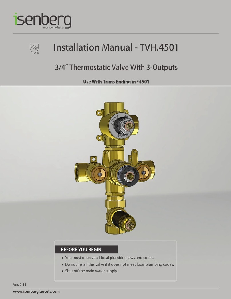
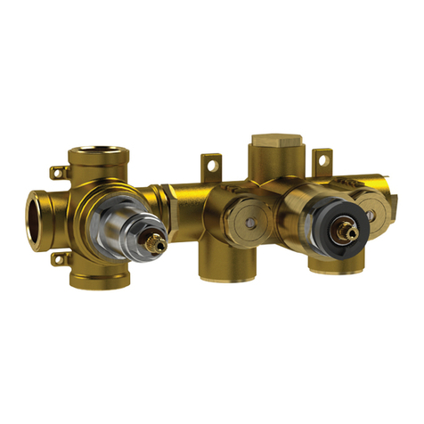
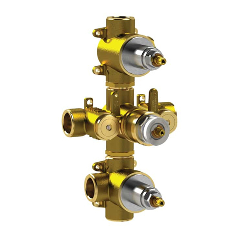
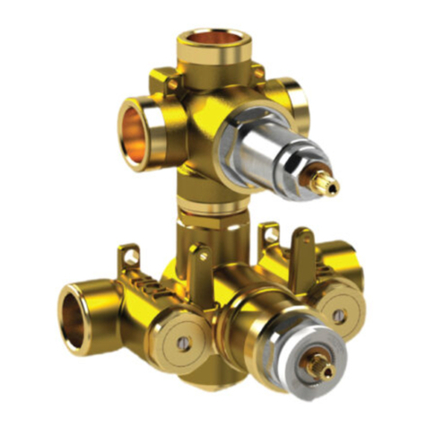
Isenberg TVH.4420F User manual

www.isenbergfaucets.com
Ver. 2.54
BEFOREYOUBEGIN
•Youmustobservealllocalplumbinglawsandcodes.
•Donotinstallthisvalveifitdoesnotmeetlocalplumbingcodes.
•Shutoffthemainwatersupply.
InstallationManual
3/4”ThermostaticValveWith2or3OutputDiverter
TVH.4301F
3OUTPUT
TVH.4420F
2OUTPUT

NOTICETOHOMEOWNER
•
We
recommendthatthisproductisinstalledbyaqualified
professionalplumber.
•Pleasecheckthisproductimmediatelytoensurethatithas
notbeendamagedandiscomplete.Beforeinstallation,please
makesurethisproductisthecorrectmodelandyouhaveall
thepartsrequiredforinstallationanduse.
•Pleaseflushthewatersystemtoensurethatnometalswarf,
solder,andotherimpuritiescanentertheproduct.
•
Turnoffwatersupplybeforecommencingwork.
•Pleasereadtheseinstructionscarefullyandretainforfuture
reference.
www.isenbergfaucets.com
TABLEOFCONTENTS
•
OperatingSpecifications . . . . . . . 1
ValveInstallationAndTolerance
Cut-OutDimensions . . . . . . . 1
RoughInSpecification . . . . . . 2
ConnectingTheSupply&OutputLines . . . . . 3
FinishedTilePosition . . . . . . . . 5
UsingTheSupplyStops . . . . . . . 6
FlushingTheValve . . . . . . . . 6
InstallingTheTrim . . . . . . . . 7
ReplacingTheThermostaticCartridge . . . . . 11
ReplacingDiverterCartridge . . . . . . . 11
ReplacingSupplyStops . . . . . . . 12
InstallingTheExtensionKit . . . . . . . 13
•
•
•
•
•
•
•
•
•
•
•
•

WATERTEMPERATURE
ThisvalvemeetsorexceedsANSIA112.18.1andASSE1016
ThisvalveiscertifiedbyIAPMO
WATERPRESSURE
Thisproductistobeusedwithawater
pressurerangeof15PSIto80PSIONLY
Ifwaterpressureisgreaterthan80PSI
installapressurereducingvalve(PRV)
Thisproductistobeusedwithwaterat
atemperaturerangeof40˚F-120˚F
ONLY!
www.isenbergfaucets.com
OPERATINGSPECIFICATIONS
CUTOUTDIMENSIONS
IsenbergʼsTVHSeriesvalvescomeswithablack
pre-attachedmud-guard.Thismud-guardisnot
toberemovedordiscarded.Itspurposeisto
guidetheinstallationprofessionalontheproper
cut-outdimensionsofthedrywall.
Wall Cut Out Dimensions
From Center Point of Valve:
X = 165mm / 6.49”
Y = 113mm / 4.44”
X
Y
1

www.isenbergfaucets.com
ROUGHINSPECIFICATION
The distance between back of
the valve to the nished tile
surface should be between
2.77” and 3.44” inches.
Minimum = 70.5mm [2,77"]
Maximum = 87.5mm [3,44"]
Finished tile should fall
between Min & Max.
If valve is installed too deep
into the wall, extensions are
available.
2

www.isenbergfaucets.com
CONNECTINGTHESUPPLY&OUTPUTLINES
FixValveonwoodenplank LevelValve
AttachHot/ColdLines
3

www.isenbergfaucets.com
CONNECTINGTHESUPPLY&OUTPUTLINES
TWOOUTPUTCONFIGURATION
VALVE:TVH.4420F
Connectthetwooutputsupplylinesas
seenontheleft.
Donotconnectanyotherway.
THREEOUTPUTCONFIGURATION
VALVE:TVH.4301F
Connectthethreeoutputsupplylinesas
seenontheleft.
4

www.isenbergfaucets.com
FINISHEDTILEPOSITION
InstallDrywallandTile.Ensurefinishedtile
surfaceisbetweentheminandmaxmarks
onthemudguards.
5

www.isenbergfaucets.com
USINGTHESUPPLYSTOPS
TurnClock-wise5timestostopwaterflow.
[Threeoutputvalveversionshowerhere]
FLUSHINGTHEVALVE
Inordertocleardirtinthelines-
youmustflushthevalvebeforethe
wallisclosedandwateristurnedon
forthefirsttime.
1)Removethe2supplystopsby
turningwithaspanner
2)Removethermostaticcartridge
byturningwithaspanner
3)Turnonwatersupplyandlet
waterflowremovinganydirtinthe
lines.
6

www.isenbergfaucets.com
INSTALLINGTHETRIM-TRIMPLATESIZEANDSHAPEMAYVARY-ILLUSTRATIONONLY
Removemudguards Install42mmring
Ahardpushmayberequired The42mmringmustbeflush.Otherwisethehandle
willnotfitproperly
7

www.isenbergfaucets.com
INSTALLINGTHETRIM-TRIMPLATESIZEANDSHAPEMAYVARY-ILLUSTRATIONONLY
Inserttrimplate
AlignTrimplatetillitisstraight
Insertadaptorbaseandtighten Insertcenteringknob&screws
8

www.isenbergfaucets.com
INSTALLINGTHETRIM-TRIMPLATESIZEANDSHAPEMAYVARY-ILLUSTRATIONONLY
Insertdiverterhandle.Tightenhexscrew&insert
coverbutton.Makesurethediverterissettothe
“OFF”markingbeforeyourbegin
Removeanti-scaldtemperaturering
9
Caliberatecartridgebeforeinsertingtemperature
handle.Redmarksmustalign.
Correctlyre-insertanti-scaldtemperatureringintherightposition.To
decreasemaximumtemperature,removehandleandrotatetheanti-
scaldringclockwise.Toincreasemaximumtemperaturerotatethe
anti-scaldringcounter-clockwise.
C
O
L
D
H
O
T

www.isenbergfaucets.com
INSTALLINGTHETRIM-TRIMPLATESIZEANDSHAPEMAYVARY-ILLUSTRATIONONLY
Inserttemperaturehandle.Tightenhexscrew&
insertcoverbutton
Thisphotoshowsacompletelyinstalledtrim
Thebuttononthetemperaturehandleisananti
scaldfeature.Inordertorotatethehandlefurther
to“HOT”thebuttonmustbepressed
10

REPLACINGTHEDIVERTERCARTRIDGE
www.isenbergfaucets.com
REPLACINGTHETHERMOSTATICCARTRIDGE
1.RemoveAnti-ScaldRing
2.Thetemperaturecartridgecanbe
removedeasilyinoneoperationby
usingaspanner.
1.RemoveThreadedRodusingaspanner
2.Removediverterflange
3.Removecartridgebyturningwithaspan-
nerandpullingoutwithapairofpliers.
11

Useaspannertotwistintheshownpositionand
removesupplystop
www.isenbergfaucets.com
REPLACINGTHESUPPLYSTOPS
12
Inordertoremovethesupplystopsdonottwistthe
screwinthemiddleofthesupplystop

www.isenbergfaucets.com
INSTALLINGEXTENSIONSTOTHEVALVE-OPTIONAL-ACTUALVALVEMAYVARY
Installdiverterextensionkit-3Piecesasshown
above
Removeantiscaldtemperaturering
Installtemperatureextensionpieceasshown
above.TightenScrew
13

USETHEFOLLOWING
INSTALLATIONMANUAL
FORTHETVH.4420VALVE

www.isenbergfaucets.com
Ver. 2.54
BEFOREYOUBEGIN
•Youmustobservealllocalplumbinglawsandcodes.
•Donotinstallthisvalveifitdoesnotmeetlocalplumbingcodes.
•Shutoffthemainwatersupply.
InstallationManual-TVH.4420
3/4”ThermostaticValveWith2-OutputDiverter
UseWithTrimsEndingin*4420/*4421/*4422

NOTICETOHOMEOWNER
•
We
recommendthatthisproductisinstalledbyaqualified
professionalplumber.
•Pleasecheckthisproductimmediatelytoensurethatithas
notbeendamagedandiscomplete.Beforeinstallation,please
makesurethisproductisthecorrectmodelandyouhaveall
thepartsrequiredforinstallationanduse.
•Pleaseflushthewatersystemtoensurethatnometalswarf,
solder,andotherimpuritiescanentertheproduct.
•
Turnoffwatersupplybeforecommencingwork.
•Pleasereadtheseinstructionscarefullyandretainforfuture
reference.
www.isenbergfaucets.com
TABLEOFCONTENTS
•
OperatingSpecifications . . . . . . . 1
ValveInstallationAndTolerance
Cut-OutDimensions . . . . . . . 1
RoughInSpecification . . . . . . 2
ConnectingTheSupply&OutputLines . . . . . 3
TrimMarkings/WaterOutput . . . . . . 4
UsingTheSupplyStops . . . . . . . 5
FlushingTheValve . . . . . . . . 5
InstallingTheTrim . . . . . . . . 6
ReplacingTheThermostaticCartridge . . . . . 10
ReplacingDiverterCartridge . . . . . . . 10
ReplacingSupplyStops . . . . . . . 11
InstallingTheExtensionKit . . . . . . . 12
CartridgeMaintenance . . . . . . . 13
•
•
•
•
•
•
•
•
•
•
•
•
•

WATERTEMPERATURE
ThisvalvemeetsorexceedsANSIA112.18.1andASSE1016
ThisvalveiscertifiedbyIAPMO
WATERPRESSURE
Thisproductistobeusedwithawater
pressurerangeof15PSIto80PSIONLY
Ifwaterpressureisgreaterthan80PSI
installapressurereducingvalve(PRV)
Thisproductistobeusedwithwaterat
atemperaturerangeof40˚F-120˚F
ONLY!
www.isenbergfaucets.com
OPERATINGSPECIFICATIONS
CUTOUTDIMENSIONS
IsenbergʼsTVHSeriesvalvescomeswithablack
pre-attachedmud-guard.Thismud-guardisnot
toberemovedordiscarded.Itspurposeisto
guidetheinstallationprofessionalontheproper
cut-outdimensionsofthedrywall.
Wall Cut Out Dimensions
From Center Point of Valve:
TVH.4420
X = 165mm / 6.49”
Y = 113mm / 4.44”
X
Y
1

www.isenbergfaucets.com
ROUGHINSPECIFICATION
The distance between back of
the valve to the nished tile
surface should be between
2.77” and 3.44” inches.
Minimum = 70.5mm [2,77"]
Maximum = 87.5mm [3,44"]
Finished tile should fall
between Min & Max.
If valve is installed too deep
into the wall, extensions are
available.
2
This manual suits for next models
2
Table of contents
Other Isenberg Control Unit manuals