Iseo Zero1 Atlas Plus User manual

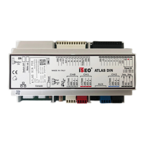
Atlas Plus DIN PoE
INSTALLATION GUIDE (EN)
ELECTRONIC SUPPORT SERVICE
iseozero1.com
®
iseo.com
Iseo Serrature s.p.a
Via San Girolamo 13
25055 Pisogne (BS)
ITALIA
Tel. +39 0364 8821
Non contractual document. Subjecet to change. Cod. 6000520POE000.3 - 30/03/2020
Atlas DIN PoE Installation Guide (EN) - © 2020 Iseo Serrature S.p.a. - www.iseo.com
Cod.5E052016
1. TECHNICAL FEATURES
Communicationinterfaces:
- 1 Ethernet interface TCP/IP 10/100 base T
- 1 LOCKBUS channel (CH0) toconnect Stylos
onlinereaders and Actuators (max 8+8 for Atlas
DIN and max 4 readers only for Atlas DIN PoE)
-
2 RS485 channels (CH1/CH2) to connect F9000
online readers (max 1 per channel)
- 1 USB 2.0 Type A
- 1 serial interface (debug)
Power supply:
- 12
÷
24 Vdc or PoE
- Maximum power consumption 10W (with no
connected devices)
PoE power supply :
- Requires PoESwitch IEEE 802.3af up to 15,4W
- Atlas DIN PoE absorbed power = 12W
- Delivery of dataand power over CAT5e/CAT6
Ethernet cable
Internal Backup battery:
- 1500mAh(7,2Vdc) NiMH battery pack
- Estimated backup time: 30 minutes
CPU and memory:
- ARM 9 based CPU module
- 800MHz CPU clock
- 512MB Flash memory
- 64MBSDRAM
- 8GB Micro-SD
Onboard Relays (max 30V - 5A):
- Relay 1 = normally open (NO)
- Relay 2 = normally open (NO)
Operativesystem:
- Linux
Push buttons:
- Reset (to manually reboot the Atlas)
- Wake-up(to manually start theAtlas when OFF)
- Switch off (tomanually switch off the Atlas)
Housing:
- DIN35 rail installation housing (white color)
- L x W x H = 160 x 90 x 60 mm (9 modules)
Environmental characteristics:
- Operating temperature: -10°C ÷ +50°C
- Storage temperature: -20°C ÷ +70°C
Conformity certifications:
- 2014/53/EU RED
- RoHS (electrical and electronic equipment).
-
References standards: EN301 489-1, EN301
489-17, EN330 440, EN60950-1, EN62209-2.
- For details
see Declarations of Conformity
available at iseo.com website (download area).
Package contents:
- 1 Atlas Plus DIN Server for RFID and F9000 ON-LINE
and OFF-LINE devices, with connectors.
- Installation guide.
WARNING: POWER SUPPLY NOT INCLUDED
(Cod.5E3005)
IT
EN
DE
Pericolo d’esplosione sela batteriaèsostituita con altra di tipo errato. Smaltire le batterie esauritein basealle leggi e alle norme ambientali locali.
Riskof explosion if the battery is replaced with an incorrect type. Dispose of used battery accordingto your local environmental laws and rules.
Es besteht Explosionsgefahr, wenn die Batterie mit einem falschen Typersetzt wird. Entsorgen Sie verbrauchte Batterien umgehend und im Einklang mit den
örtlichen Umweltgesetzen und Richtlinien.
FR
ES
NL
Risque d'explosion si la batterie est remplacée par un type incorrect. Eliminez les batteries usagées conformément aux règles et lois environnementales locales
en vigueur.
Riesgo de explosión si la batería es remplazada por una incorrecta. Deseche la batería usada de acuerdo con las leyes y normas ambientales en vigor.
Er bestaat een risico van explosie op het moment dat de batterij wordt vervangen voor een incoorect type. Voer gebruikte batterijen af volgens de plaatselijke
milieuwetten en -regels.
ATTENZIONE - ATTENTION - ATENCIÓN - AUFMERKSAMKEIT - AANDACHT
NiMH 7,2V 1500mA
NiMH battery pack
7,2 V - 1500 mAh
INDEX
INSTALLATION GUIDE (EN)
GUIDA INSTALLATIONE (IT)
INSTALLATIONSANLEITUNG (DE)
GUIDE D’INSTALLATION (FR)
1
5
9
13
GUÍA DE INSTALACIÓN (ES) 17

2. ATLAS INSTALLATION Connect to 192.168.0.184 from Google Chrome,
Microsoft Edge or Apple Safari Internet browser.
Lift up and remove
the white cover
1
Move the jumper on
Battery ON
2
Check the green
Power IN LED is ON
4
Lockbus
channel RS485
channels
Onboard
Relays
ATLAS DIN PoE
Console
Battery
ON
Reset
Wake up
Switch OFF
ON
GND
+5V
+V OUT
OUT 1
IN 1
GND
Analog IN
GND
+V Power
GND
SER. A
SER. B
COM
NO
NO
COM
R
USB
CH0
Relay
1
Relay
2
IN 2
IN 5
IN 3
IN 4
GND
+5V
R 1
R 3
LED 2
LED 1
R 2
R 5
R 4
+V Power
GND
SER. A
SER. B
CH1
AUX
+V Power
GND
SER. A
SER. B
CH2
Power IN
12 VDC - 800 mA
24 VDC - 400 mA
MADE IN ITALY
PoE
Connect the CAT5e/CAT6
Ethernet cable coming from
the Switch PoE (cable and
switch PoE not included)
3
(Wire connected between
+V OUT and +Power IN)
To PoE Switch
(IEEE 802.3af
up to 15,4W)
DO NOT REMOVE!
Color
Green
Red
Orange
Description
Power IN active
Switch OFF
Backup battery
pack operating
Orange
Orange
Orange
Orange
Ethernet activity
Serial Tx/Rx CH0
Serial Tx/Rx CH1
Serial Tx/Rx CH1
LED reference table
Ref.
ON
OFF
BATT
ETH
TX/RX
TX/RX
TX/RX
ON
OFF
BATT
ETH TX/RX TX/RX TX/RX
For future
developments
Battery
ON
WARNINGS
https://www.iseo.com/it/en/download
Read this manual prior to use the device in order to ensure a safe and proper use.
Preserve this manual as future reference.
The installation and maintanance of the device must be carried out by qualified technical staff, adequately trained by ISEO.
The instructions should be carefully followed during installation. These instructions and any maintenance instructions should be passed on by the installer
to the user.
No modifications of any kind are permitted, except for those described in these instructions.
The product must be destined only for the use for which it is expressly designed and therefore as web server controller for civil and industrial locations.
Any other use is considered improper and dangerous.
The electrical connection must be made according to the constructor's instructions and respecting the regulations in force.
For all repairs, exclusively contact a technical assistance center authorized by the constructor.
Disconnect the power supply before carrying out any technical service that involves opening or accessing the internal parts of the product.
Dispose of the product separately from household waste, in accordance with local laws and regulations.
Ensure full recharge of the Atlas internal battery by running a full recharge cycle (24 hours), minimun every 6 months.
The calculation of the cables section must be performed by qualified staff.
Max cable length of LOCKBUS channel is 100 mt (sum of all branches).
Recommended voltage for LOCKBUS channel is 24 VDC.
In case of power failure the rechargeable battery inside the Atlas ensure power for 30 minutes max.
It is advisable to provide for an appropriate sectioning, a protection switch upstream of the transformer.
For any technical assistance or repairs, contact only Iseo Serrature or an Iseo Zero1 authorised technical centre.
Iseo Zero1 reserves the right, without prior notice, to make all the necessary modifications to the product and to the instruction manual, for quality
improvements or manufacturing or marketing needs.
Atlas earth connection is mandatory.
Add Surge Protection Devices (SPD) to the mains, upstream the Atlas Master, when connected to Atlas Slaves, Actuators and Readers placed in outside
areas of the builing (not equipotential zones), according to the Lightning Protection Risk Assessment of your building and current legislations.

3. V364 RFID SYSTEM WIRING:
2 DOORS CONTROLLER CONNECTION EXAMPLE
Devices consumption:
- ATLAS = 10 W
- Stylos = 3W
Suggested configuration for 2 doors
controller: max 4 Stylos readers.
ATLAS DIN PoE
Console
Battery
ON
Reset
Wake up
Switch OFF
ON
GND
+5V
+V OUT
OUT 1
IN 1
GND
Analog IN
GND
+V Power
GND
SER. A
SER. B
COM
NO
NO
COM
R
USB
CH0
Relay
1
Relay
2
IN 2
IN 5
IN 3
IN 4
GND
+5V
R 1
R 3
LED 2
LED 1
R 2
R 5
R 4
+V Power
GND
SER. A
SER. B
CH1
AUX
+V Power
GND
SER. A
SER. B
CH2
Power IN
12 VDC - 800 mA
24 VDC - 400 mA
MADE IN ITALY
PoE
To PoE Switch
(IEEE 802.3af
up to 15,4W)
12 VAC
12 VAC
DOOR 1
Back sideview
circuit board
DOOR1 IN
(Stylos cod.5E1310126)
S1
DOOR 2
Total LOCKBUS channel cable length (sum of all
branches): MAX 100mt.
Conductor capacitance < 100pF/m.
Conductors electrical resistance max 90 ohm/Km.
Cable 3 x 0,75mm - AWG 18 (
the calculation of the
cables section must be verified by qualified staff).
WIRING SPECIFICATIONS
LOCKBUS
(+) V ALIM
( ) GND
DOOR 2 IN
(Stylos cod.5E1310126)
Back side view
circuit board
Back sideview
circuit board
DOOR 1 OUT
(Stylos cod.5E1310126)
S1
DOOR2 OUT
(Stylos cod.5E1310126)
Back side view
circuit board
2
Wires colors reported in the wiring diagrams are just an example.
For the Stylos address configuration refer to the
Stylos Installation Guide, available at: iseo.com.

4. V364 F9000 SYSTEM WIRING:
2 DOORS CONTROLLER CONNECTION EXAMPLE
Devices consumption:
- ATLAS = 10 W
- F9000 reader = 1W
Maximum number of devices that can be
connected to the RS485 channel = 1 (per
channel).
ATLAS DIN PoE
Console
Battery
ON
Reset
Wake up
Switch OFF
ON
GND
+5V
+V OUT
OUT 1
IN 1
GND
Analog IN
GND
+V Power
GND
SER. A
SER. B
COM
NO
NO
COM
R
USB
CH0
Relay
1
Relay
2
IN 2
IN 5
IN 3
IN 4
GND
+5V
R 1
R 3
LED 2
LED 1
R 2
R 5
R 4
+V Power
GND
SER. A
SER. B
CH1
AUX
+V Power
GND
SER. A
SER. B
CH2
Power IN
12 VDC - 800 mA
24 VDC - 400 mA
MADE IN ITALY
PoE
WIRING SPECIFICATIONS
Maximum Ethernet cable length between Atlas and F9000 Reader: 500mt.
Ethernet cable FTP AWG24 CAT5E (and above).
Connect 120 ohm (1/4W) resistor, on both Atlas and F9000 Reader sides, as shown inthe scheme.
Conductor capacitance < 100pF/m.
Conductors electrical resistance max 90 ohm/Km.
SER.A/B
SER.A/B
+ V Power
GND
Shield
DOOR 2
(F9000 reader
cod.E03222)
DOOR 1
(F9000 Reader
cod.E03222)
12 VAC
12 VAC
DOOR 1
DOOR 2
Wires colors reported in the wiring diagrams are just an example.
To PoE Switch
(IEEE 802.3af
up to 15,4W)

Atlas Plus DIN PoE
GUIDA INSTALLAZIONE (IT)
ELECTRONIC SUPPORT SERVICE
iseozero1.com
®
iseo.com
Iseo Serrature s.p.a
Via San Girolamo 13
25055 Pisogne (BS)
ITALIA
Tel. +39 0364 8821
Documento non contrattuale. Soggetto a modifica. Cod. 6000520POE000.3 - 30/03/2020
Atlas DIN PoE Guida Installazione (IT) - © 2020 Iseo Serrature S.p.a. - www.iseo.com
Cod.5E052016
1. CARATTERISTICHE TECNICHE
Interfacce di comunicazione:
-
1 interfaccia Ethernet TCP/IP 10/100 base T
- 1 canale LOCKBUS (CH0) per connettere lettori
Stylos online e Attuatori (max 8+8 per Atlas DIN e
max solo 4 lettori per Atlas DIN PoE)
- 2 canali RS485 (CH1/CH2) per connettere i lettori
F9000 online (max 1 per canale)
- 1 USB 2.0 Tipo A
- 1 interfaccia seriale (debug)
Alimentazione:
- 12÷24 Vdc o PoE
- Potenza massima assorbita 10W (senza dispositivi
collegati)
Alimentazione PoE:
- Richiede uno switch PoE IEEE 802.3af fino a 15,4W
- Potenza assorbita Atlas DIN PoE = 12W
- Trasmissione di dati e alimentazione tramite cavo
Ethernet CAT5e/CAT6
Batteria di backup interna:
- Pacco batterie 1500mAh (7,2Vdc) NiMH
- Tempo di backup stimato: 30 minuti
CPU e memoria:
- modulo CPU ARM 9
- orologio 800MHz CPU
- Flash memory 512MB
- 64MB SDRAM
- 8GB Micro-SD
Relè integrati (max 30V - 5A):
- Relè 1 = normalmente aperto (NO)
- Relè 2 = normalmente aperto (NO)
Sistema operativo:
- Linux
Pulsanti:
- Reset (per effettuare manualmente il reboot
dell’Atlas)
- Wake-up (per accendere manualmente l’Atlas
quando è spento)
- Switch off (per spegnere manualmente l’Atlas)
Scatola:
- Scatola per installazione su barra DIN35 (colore
bianco)
- L x L x A = 160 x 90 x 60 mm (9 moduli)
Caratteristiche ambientali:
- Temperatura di operatività: -10°C ÷ +50°C
- Temperatura di stoccaggio: -20°C ÷ +70°C
Certificazioni di conformità:
- 2014/53/EU RED
- RoHS (apparecchiature elettriche ed elettroniche).
- Standard di riferimento: EN301 489-1, EN301
489-17, EN330 440, EN60950-1, EN62209-2.
- Per dettagli consulta le Dichiarazioni di Conformità
disponibili sul sito web iseo.com (area download).
Contenuto della confezione:
- Server Atlas Plus DIN per dispositivi RFID e F9000
ON-LINE e OFF-LINE, con i connettori.
- Guida Installazione
ATTENZIONE: ALIMENTATORE NON INCLUSO
(Cod. 5E3005)
IT
EN
DE
Pericolo d’esplosione sela batteriaèsostituita con altra di tipo errato. Smaltire le batterie esauritein basealle leggi e alle norme ambientali locali.
Riskof explosion if the battery is replaced with an incorrect type. Dispose of used battery accordingto your local environmental laws and rules.
Es besteht Explosionsgefahr, wenn die Batterie mit einem falschen Typersetzt wird. Entsorgen Sie verbrauchte Batterien umgehend und im Einklang mit den
örtlichen Umweltgesetzen und Richtlinien.
FR
ES
NL
Risque d'explosion si la batterie est remplacée par un type incorrect. Eliminez les batteries usagées conformément aux règles et lois environnementales locales
en vigueur.
Riesgo de explosión si la batería es remplazada por una incorrecta. Deseche la batería usada de acuerdo con las leyes y normas ambientales en vigor.
Er bestaat een risico van explosie op het moment dat de batterij wordt vervangen voor een incoorect type. Voer gebruikte batterijen af volgens de plaatselijke
milieuwetten en -regels.
ATTENZIONE - ATTENTION - ATENCIÓN - AUFMERKSAMKEIT - AANDACHT
NiMH 7,2V 1500mA
NiMH battery pack
7,2 V - 1500 mAh
INDEX
INSTALLATION GUIDE (EN)
GUIDA INSTALLATIONE (IT)
INSTALLATIONSANLEITUNG (DE)
GUIDE D’INSTALLATION (FR)
1
5
9
13
GUÍA DE INSTALACIÓN (ES) 17

2. INSTALLAZIONE ATLAS Connettersi a 192.168.0.184 da browser Internet
Google Chrome, Microsoft Edge o Apple Safari.
Sollevare e rimuovere
la cover bianca
1
Spostare il jumper
su Batteria ON
2
Controllare che il LED verde
dell’alimentazione sia ON
4
Canale
Lockbus Canali
RS485
Relè a bordo
ATLAS DIN PoE
Console
Battery
ON
Reset
Wake up
Switch OFF
ON
GND
+5V
+V OUT
OUT 1
IN 1
GND
Analog IN
GND
+V Power
GND
SER. A
SER. B
COM
NO
NO
COM
R
USB
CH0
Relay
1
Relay
2
IN 2
IN 5
IN 3
IN 4
GND
+5V
R 1
R 3
LED 2
LED 1
R 2
R 5
R 4
+V Power
GND
SER. A
SER. B
CH1
AUX
+V Power
GND
SER. A
SER. B
CH2
Power IN
12 VDC - 800 mA
24 VDC - 400 mA
MADE IN ITALY
PoE
Collegare il cavo Ethernet
CAT5e / CAT6 proveniente
dallo Switch PoE (cavo e
Switch PoE non incluso)
3
(Cavo collegato tra
+V OUT e +Power IN)
Allo Switch PoE
(IEEE 802.3af
fino a 15,4W)
NON RIMUOVERE!
Colore
Verde
Rosso
Arancione
Descrizione
Alimentazione attiva
Switch OFF
Backup pacco
batterie operative
Arancione
Arancione
Arancione
Arancione
Attività Ethernet
Serial Tx/Rx CH0
Serial Tx/Rx CH1
Serial Tx/Rx CH1
Tabella di riferimento LED
Rif.
ON
OFF
BATT
ETH
TX/RX
TX/RX
TX/RX
ON
OFF
BATT
ETH TX/RX TX/RX TX/RX
Per sviluppi
futuri
Batteria
ON
AVVERTENZE
Si prega di leggere questo manuale prima di utilizzare il dispositivo per garantire un uso sicuro e corretto.
Conserva questo manuale come riferimento futuro.
L’installazione e la manutenzione di questo dispositivo deve essere effettuata da personale tecnico qualificato, adeguatamente formato da ISEO.
Le istruzioni devono essere attentamente seguite durante l’installazione. Queste istruzioni e qualsiasi altra istruzione di manutenzione deve essere
trasferita dall’installatore all’utilizzatore.
Nessuna modifica di alcun tipo è permessa, ad eccezione di quelle descritte in queste istruzioni.
Il prodotto deve essere destinato esclusivamente all'uso per il quale è espressamente progettato e quindi come controller di server Web per sedi civili
e industriali. Ogni altro uso è considerato improprio e pericoloso.
Il collegamento elettrico deve essere eseguito secondo le leggi vigenti da personale qualificato.
Per tutte le riparazioni contattare esclusivamente i centri di assistenza tecnica autorizzati dal costruttore.
Scollegare l'alimentazione prima di eseguire qualsiasi servizio tecnico che comporti l'apertura o l'accesso alle parti interne del prodotto.
Smaltire il prodotto separatamente dai rifiuti domestici, in conformità con le leggi e i regolamenti locali.
Garantire la ricarica completa della batteria interna dell’Atlas eseguendo un ciclo di ricarica completo (24 ore), minimo ogni 6 mesi.
Il calcolo della sezione dei cavi deve essere effettuato da personale qualificato.
La massima lunghezza del cavo del canale LOCKBUS è 100 mt (somma di tutti i rami).
Il voltaggio consigliato per il canale LOCKBUS è 24 VDC.
In caso di interruzione di corrente la batteria ricaricabile all’interno dell’Atlas garantisce l’alimentazione per massimo 30 minuti.
Per una corretta protezione dell’impianto elettrico, è consigliabile prevedere un interruttore di protezione a monte del trasformatore.
Per assistenza tecnica o riparazioni, contatta esclusivamente Iseo Serrature o un centro tecnico autorizzato Iseo Zero1.
Iseo Zero1 si riserva il diritto, senza preavviso, di apportare tutte le modifiche necessarie al prodotto e al manuale di istruzioni, per miglioramenti di qualità o
necessità di produzione o di marketing.
La connessione a terra dell’Atlas è obbligatoria.
Se l’Atlas Master è collegato ad Altas Slave, Attuatori e Lettori, collocati in aree esterne all’edificio principale (zone non equipotenziali), aggiungere alla rete
elettrica, a monte dell'Atlas Master, dei Dispositivi di Protezione da Sovratensioni (Surge Protection Devices - SPD). Questo in ottemperanza alla Valutazione del
Rischio di Protezione contro i Fulmini del tuo edificio secondo le legislazioni vigenti.
https://www.iseo.com/it/it/download

Consumi dispositivi:
- ATLAS = 10 W
- Stylos = 3W
Configurazione suggerita per la gestione di
2 porte: max 4 lettori Stylos.
ATLAS DIN PoE
Console
Battery
ON
Reset
Wake up
Switch OFF
ON
GND
+5V
+V OUT
OUT 1
IN 1
GND
Analog IN
GND
+V Power
GND
SER. A
SER. B
COM
NO
NO
COM
R
USB
CH0
Relay
1
Relay
2
IN 2
IN 5
IN 3
IN 4
GND
+5V
R 1
R 3
LED 2
LED 1
R 2
R 5
R 4
+V Power
GND
SER. A
SER. B
CH1
AUX
+V Power
GND
SER. A
SER. B
CH2
Power IN
12 VDC - 800 mA
24 VDC - 400 mA
MADE IN ITALY
PoE
Allo Switch PoE
(IEEE 802.3af
fino a 15,4 W)
3. CABLAGGIO SISTEMA V364 RFID:
ESEMPIO DI CONNESSIONE PER LA GESTIONE DI 2 PORTE
12 VAC
12 VAC
PORTA 1
PORTA 1 IN
(Stylos cod.5E1310126)
S1
PORTA 2
PORTA 2 IN
(Stylos cod.5E1310126)
PORTA 1 OUT
(Stylos cod.5E1310126)
S1
PORTA 2 OUT
(Stylos cod.5E1310126)
Lunghezza totale dei cavi collegati al canale LOCKBUS
(somma di tutti i rami): MAX 100 mt.
Capacità conduttore < 100 pF/m.
Resistenza elettrica del conduttore max 90 ohm/Km.
Cavo allarme 3 x 0,75mm - AWG 18 (il calcolo della
sezione dei cavi deve essere verificato da personale
qualificato).
SPECIFICHE CABLAGGI
LOCKBUS
(+) V ALIM
( ) GND
2
I colori dei cablaggi riportati negli schemi elettrici sono solo
un esempio.
Vista retro scheda
elettronica Vista retro scheda
elettronica
Vista retro scheda
elettronica Vista retro scheda
elettronica
Per la configurazione degli indirizzi dello Stylos,
consultare la Guida Installazione Stylos al sito:
iseo.com.

Consumi dispositivi:
- ATLAS = 10 W
- Lettore F9000 = 1W
Numero massimo di dispositivi collegabili
ai canali RS485 = 1 (per canale).
ATLAS DIN PoE
Console
Battery
ON
Reset
Wake up
Switch OFF
ON
GND
+5V
+V OUT
OUT 1
IN 1
GND
Analog IN
GND
+V Power
GND
SER. A
SER. B
COM
NO
NO
COM
R
USB
CH0
Relay
1
Relay
2
IN 2
IN 5
IN 3
IN 4
GND
+5V
R 1
R 3
LED 2
LED 1
R 2
R 5
R 4
+V Power
GND
SER. A
SER. B
CH1
AUX
+V Power
GND
SER. A
SER. B
CH2
Power IN
12 VDC - 800 mA
24 VDC - 400 mA
MADE IN ITALY
PoE
Allo Switch PoE
(IEEE 802.3af
fino a 15,4 W)
4. CABLAGGIO SISTEMA V364 F9000:
ESEMPIO DI CONNESSIONE PER LA GESTIONE DI 2 PORTE
PORTA 2
(Lettore F9000
cod.E03222)
PORTA 1
(Lettore F9000
cod.E03222)
12 VAC
12 VAC
PORTA 1
PORTA 2
SPECIFICHE CABLAGGI
Massima lunghezza del cavo Ethernet tra Atlas e Lettore F9000: 500 mt.
Cavo Ethernet FTP AWG24 CAT5E (o superiore).
Collegare una resistenza da 120 ohm (1/4 W), sia lato Atlas che lato Lettore F9000, come mostrato nello schema.
Capacità conduttore < 100 pF/m.
Resistenza elettrica del conduttore max 90 ohm/Km.
SER.A/B
SER.A/B
+ V Power
GND
Schermo
I colori dei cablaggi riportati negli schemi elettrici sono solo un esempio.

Atlas Plus DIN PoE
INSTALLATIONSANLEITUNG (DE)
ELECTRONIC SUPPORT SERVICE
iseozero1.com
®
iseo.com
Iseo Serrature s.p.a
Via San Girolamo 13
25055 Pisogne (BS)
ITALIA
Tel. +39 0364 8821
Kein rechtsverbindliches Dokument. Änderungen und Irrtümer vorbehalten. Cod. 6000520POE000.3 - 30/03/2020
Atlas DIN PoE Installationsanleitung (DE) - © 2020 Iseo Serrature S.p.a. - www.iseo.com
Cod.5E052016
1. TECHNISCHE DATEN
Kommunikationsschnittstellen:
- 1 Ethernet Schnittstelle TCP/IP 10/100 base T
- 1 LOCKBUS Kanal (CH 0) zum Anschluss von Stylos
Online Lesern und Aktuatoren (max. 8+8 bei Atlas
DIN und max. 4 Leser nur bei Atlas DIN PoE)
-
2 RS485 Kanäle (CH1/CH2) zum Anschluss von F9000
Online Lesern (max 1 pro Kanal)
- 1 USB 2.0 Typ A
- 1 serielle Schnittstelle (debug)
Spannungsversorgung:
- 12 bis 24 V DC oder PoE
- Maximaler Verbrauch 10 W (wenn keine weiteren
Geräte angeschlossen sind)
PoE Spannungsversorgung:
- Benötigt PoE-Switch IEEE 802.3af bis zu 15,4W
- Atlas DIN PoE Einspeiseleistung = 12W
- Daten- und Energieübertragung über CAT5e/CAT6
Netzwerkkabel
Interne Stützbatterie:
- 1500mAh(7,2Vdc) NiMH Batterie
- geschätzte Überbrückungszeit: 30 Minuten
CPU and Speicher:
- ARM 9 basierendes CPU Modul
- 800MHz CPU Takt
- 512MB Flash Speicher
- 64MBSDRAM
- 8GB Micro-SD
Onboard Relais (max 30V - 5A):
- Relais 1 = Schließer (NO)
- Relais 2 = Schließer (NO)
Betriebssystem:
- Linux
Funktionstasten:
- Neustart (zum manuellen neu starten des Atlas)
- Einschalten (zum manuellen Einschalten des Atlas)
- Ausschalten (zum manuellen Einschalten des Atlas)
Gehäuse:
- DIN35 Hutschienengehäuse (weiß)
- L x B x H = 160 x 90 x 60 mm (9 Teilungseinheiten)
Umweltbedingungen:
- Betriebstemperatur: -10°C bis +50°C
- Lagertemperatur: -20°C bis +70°C
Konformitätserklärungen:
- 2014/53/EU RED
- RoHS (elektrische und elektronische Geräte).
-
Normen: EN301 489-1, EN301
489-17, EN330 440, EN60950-1, EN62209-2.
- Weitere Details zu Konformitätserklärungen
sind unter www.iseo.com verfügbar.
Verpackungsinhalt:
-
1 Atlas Plus DIN Controller für RFID und F9000 ONLINE
und OFFLINE Geräte, inkl. Steckverbindern.
- Installationsanleitung.
HINWEIS: SPANNUNGSVERSORGUNG NICHT
IM LIEFERUMFANG (Cod.5E3005)
IT
EN
DE
Pericolo d’esplosione sela batteriaèsostituita con altra di tipo errato. Smaltire le batterie esauritein basealle leggi e alle norme ambientali locali.
Riskof explosion if the battery is replaced with an incorrect type. Dispose of used battery accordingto your local environmental laws and rules.
Es besteht Explosionsgefahr, wenn die Batterie mit einem falschen Typersetzt wird. Entsorgen Sie verbrauchte Batterien umgehend und im Einklang mit den
örtlichen Umweltgesetzen und Richtlinien.
FR
ES
NL
Risque d'explosion si la batterie est remplacée par un type incorrect. Eliminez les batteries usagées conformément aux règles et lois environnementales locales
en vigueur.
Riesgo de explosión si la batería es remplazada por una incorrecta. Deseche la batería usada de acuerdo con las leyes y normas ambientales en vigor.
Er bestaat een risico van explosie op het moment dat de batterij wordt vervangen voor een incoorect type. Voer gebruikte batterijen af volgens de plaatselijke
milieuwetten en -regels.
ATTENZIONE - ATTENTION - ATENCIÓN - AUFMERKSAMKEIT - AANDACHT
NiMH 7,2V 1500mA
NiMH battery pack
7,2 V - 1500 mAh
INDEX
INSTALLATION GUIDE (EN)
GUIDA INSTALLATIONE (IT)
INSTALLATIONSANLEITUNG (DE)
GUIDE D’INSTALLATION (FR)
1
5
9
13
GUÍA DE INSTALACIÓN (ES) 17

2. ATLAS INSTALLATON Verbinden zu 192.168.0.184 mit Google Chrome,
Microsoft Edge oder Apple Safari Internet Browser.
Weiße Abdeckung
anheben und entfernen
1
Jumper auf Stellung
“Battery ON” stecken
2
Prüfen, ob Power IN
LED grün leuchtet.
4
Lockbus
Kanal RS485
Kanäle
Onboard
Relais
ATLAS DIN PoE
Console
Battery
ON
Reset
Wake up
Switch OFF
ON
GND
+5V
+V OUT
OUT 1
IN 1
GND
Analog IN
GND
+V Power
GND
SER. A
SER. B
COM
NO
NO
COM
R
USB
CH0
Relay
1
Relay
2
IN 2
IN 5
IN 3
IN 4
GND
+5V
R 1
R 3
LED 2
LED 1
R 2
R 5
R 4
+V Power
GND
SER. A
SER. B
CH1
AUX
+V Power
GND
SER. A
SER. B
CH2
Power IN
12 VDC - 800 mA
24 VDC - 400 mA
MADE IN ITALY
PoE
CAT5e/CAT6 Ethernet
Kabel mit PoE-Switch und
Atlas verbinden (Kabel und
PoE-Switch nicht im
Lieferumfang)
3
(Kabel zwischen +V OUT
und +Power IN)
Zum PoE-Switch
(IEEE 802.3af
bis zu 15,4W)
NICHT ENTFERNEN!
Farbe
Grün
Rot
Orange
Beschreibung
Power IN aktiv
Ausgeschalten
Stützbatterie imÜber-
brückungsmodus
Orange
Orange
Orange
Orange
Netzwerkaktivität
Seriell Tx/Rx CH0
Seriell Tx/Rx CH1
Seriell Tx/Rx CH1
LED Signalisierungstabelle
Ref.
ON
OFF
BATT
ETH
TX/RX
TX/RX
TX/RX
ON
OFF
BATT
ETH TX/RX TX/RX TX/RX
Für zukünftige
Erweiterungen
Battery
ON
HINWEISE
https://www.iseo.com/it/de/download
Lesen Sie diese Anleitung vor Benutzung des Gerätes, um den sachgemäßen Umgang zu gewährleisten.
Bewahren Sie diese Anleitung als künftige Referenz auf.
Die Installation und Wartung des Geräts muss durch qualifiziertes, von ISEO entsprechend geschultes technisches Personal erfolgen.
Folgen sie bei der Installation sorgfältig der Anleitung. Anleitung und ggf. Wartungsanweisungen sollten vom Installateur an den Nutzer weitergegeben
werden.
Änderungen jeglicher Art, außer der in deiser Anleitung beschriebener, sind nicht erlaubt.
Das Produkt darf nur zu dem Zweck verwendet werden, für den es konzipiert wurde, anderweitiger Gebrauch gilt als unsachgemäß und ist gefährlich.
Die elektrischen Anschlüsse sind entsprechend den Anweisungen in dieser Anleitung vorzunehmen und müssen den geltenden Vorschriften entsprechen.
Wenden Sie sich für alle Reparaturen ausschließlich an einen vom Hersteller autorisierten technischen Fachhändler.
Unterbrechen Sie die Stromzufuhr, bevor Sie technische Services durchführen, der das Öffnen oder den Zugang zu den inneren Teilen des Produkts beinhaltet.
Entsorgen Sie das Produkt getrennt vom Hausmüll, in Übereinstimmung mit den örtlichen Gesetzen und Vorschriften.
Stellen Sie sicher, dass der interne Akku des Atlas mindestens alle 6 Monate durch einen vollständigen Ladezyklus (24 Stunden) aufgeladen wird.
Die Berechnung des Kabelquerschnitts muss von qualifiziertem Personal durchgeführt werden.
Gesamte LOCKBUS Kanal Kabellänge beträgt 100 Meter (Summe aller Zweige).
Die empfohlene Spannung für den LOCKBUS-Kanal beträgt 24 VDC.
Im Falle eines Stromausfalls gewährleisten der Stützakku im Inneren des Atlas die Stromversorgung für maximal 30 Minuten.
Es ist ratsam, für eine entsprechende Trennung, einen Schutzschalter vor der Spannungsversorgung zu verbauen.
Für technische Unterstützung oder Reparaturen wenden Sie sich nur an Iseo Serrature oder an einen von Iseo Zero1 autorisierten Fachhändler.
Iseo Zero1 behält sich das Recht vor, ohne Vorankündigung alle notwendigen Änderungen am Produkt und an der Installationsanleitung vorzunehmen,
um Qualitätsverbesserungen oder Herstellungs- oder Marketinganforderungen zu erfüllen.
Eine Atlas-Erdungsverbindung ist unbedingt erforderlich.
Verwenden Sie vor dem Atlas Master Überspannungsschutzgeräte (SPD), wenn dieser mit Atlas Slaves, Aktuatoren und Lesern verbunden wird, die im
Außenbereich (mit Potentialdifferenz) platziert sind, entsprechend der Blitzschutz-Risikobewertung Ihres Gebäudes und der aktuellen Gesetzgebung.

3. V364 RFID SYSTEM VERKABELUNG:
2 TÜREN VERSCHALTUNGSBEISPIEL
Geräte-Verbrauch:
- ATLAS = 10 W
- Stylos = 3W
Empfohlene Konfiguration für 2 Türen
Controller: max. 4 Stylos Leser.
ATLAS DIN PoE
Console
Battery
ON
Reset
Wake up
Switch OFF
ON
GND
+5V
+V OUT
OUT 1
IN 1
GND
Analog IN
GND
+V Power
GND
SER. A
SER. B
COM
NO
NO
COM
R
USB
CH0
Relay
1
Relay
2
IN 2
IN 5
IN 3
IN 4
GND
+5V
R 1
R 3
LED 2
LED 1
R 2
R 5
R 4
+V Power
GND
SER. A
SER. B
CH1
AUX
+V Power
GND
SER. A
SER. B
CH2
Power IN
12 VDC - 800 mA
24 VDC - 400 mA
MADE IN ITALY
PoE
Zum PoE-Switch
(IEEE 802.3af
bis zu 15,4W)
12 VAC
12 VAC
TÜR 1
Rückansicht
Leiterplatte
TÜR 1 EINGANG
(Stylos cod.5E1310126)
S1
TÜR 2
Gesamte LOCKBUS Kanal Kabellänge (Summe aller Zweige):
Maximal 100 Meter
Leitungskapazität < 100pF/m.
Elektrischer Leitungswiderstand max. 90 Ohm/Km.
Kabel 3 x 0,75mm - AWG 18 (die Berechnung des Kabel-
querschnitts muss durch qualifiziertes Personal erfolgen.
KABEL-SPEZIFIKATIONEN
LOCKBUS
(+) V ALIM
( ) GND
TÜR 2 EINGANG
(Stylos cod.5E1310126)
Rückansicht
Leiterplatte
TÜR 1 AUSGANG
(Stylos cod.5E1310126)
S1
TÜR 2 AUSGANG
(Stylos cod.5E1310126)
Rückansicht
Leiterplatte
2
In Schaltplänen dargestellte Farben der Drähte sind nur ein Beispiel.
Die Stylos-Adresskonfiguration finden Sie im
Stylos-Installationshandbuch, verfügbar unter:
iseo.com.
Rückansicht
Leiterplatte

4. V364 F9000 SYSTEM VERKABELUNG:
2 TÜREN VERSCHALTUNGSBEISPIEL
Geräte-Verbrauch:
- ATLAS = 10 W
- F9000 Leser = 1W
Maximale Anzahl von Geräten, die an den
RS485-Kanal angeschlossen werden
können = 1 (pro Kanal).
ATLAS DIN PoE
Console
Battery
ON
Reset
Wake up
Switch OFF
ON
GND
+5V
+V OUT
OUT 1
IN 1
GND
Analog IN
GND
+V Power
GND
SER. A
SER. B
COM
NO
NO
COM
R
USB
CH0
Relay
1
Relay
2
IN 2
IN 5
IN 3
IN 4
GND
+5V
R 1
R 3
LED 2
LED 1
R 2
R 5
R 4
+V Power
GND
SER. A
SER. B
CH1
AUX
+V Power
GND
SER. A
SER. B
CH2
Power IN
12 VDC - 800 mA
24 VDC - 400 mA
MADE IN ITALY
PoE
KABEL-SPEZIFIKATIONEN
Maximale Netzwerkkabel-Länge zwischen Atlas and F9000 Leser: 500 Meter.
Netzwerkkabel FTP AWG24 CAT5E (und höher).
Verwenden Sie 120 Ohm (1/4W) Widerstände am Atlas und F9000 Leser, wie im Schema dargestellt.
Leitungskapazität < 100pF/m.
Elektrischer Leitungswiderstand max. 90 Ohm/Km.
SER.A/B
SER.A/B
+ V Power
GND
Schirm
TÜR 2
(F9000 Leser
cod.E03222)
TÜR 1
(F9000 Leser
cod.E03222)
12 VAC
12 VAC
TÜR 1
TÜR 2
In Schaltplänen dargestellte Farben der Drähte sind nur ein Beispiel.
Zum PoE-Switch
(IEEE 802.3af
bis zu 15,4W)

Atlas Plus DIN PoE
SERVICE D'ASSISTANCE ÉLECTRONIQUE
iseozero1.com
®
iseo.com
Iseo Serrature s.p.a
Via San Girolamo 13
25055 Pisogne (BS)
ITALIA
Tel. +39 0364 8821
Cod.5E052016
Document non contractuel. Sous réserve de modification. Cod. 6000520POE000.3 - 30/03/2020
Atlas DIN Guide d’Installation Guide (FR) - © 2020 Iseo Serrature S.p.a. - www.iseo.com
GUIDE D’INSTALLATION (FR) SOLUTIONS
ELECTRONIQUES
1. CARACTÉRISTIQUES TECHNIQUES
Interfaces de communication :
- 1 Interface Ethernet TCP/IP 10/100 base T
- 1 entrée LOCKBUS (CH0) pour connecter lecteurs
Stylos et connecteurs en ligne
(max 8+8 pour
l’Atlas
DIN et max 4 lecteurs pour l’Atlas DIN PoE)
-
2 entrées RS485 (CH1/CH2) pour connecter
le lecteur F9000
en ligne (max 1 par canal)
- 1 USB 2.0 Type A
- 1 interface série (débogage)
Alimentation électrique :
- 12
-
24 V DC ou PoE
- Consommation électrique maximale de 10W
(sans appareil connecté)
Alimentation électrique PoE :
- Requiert un commutateur PoESwitch IEEE 802.3
jusqu’à 15,4W
- Atlas DIN PoE puissance consommée = 12W
- Transmission de données et d’énergie
par câble Ethernet CAT5e/CAT6
Batterie de secours interne :
- Batterie NiMH 1500mAh(7,2Vdc)
- Autonomie estimée : 30 min sans alimentation
CPU et mémoire :
- Module CPU basé sur ARM 9
- Horloge CPU 800MHz
- 512 Mo de mémoire Flash
- 64MBSDRAM
- Micro-SD 8GB
Relais embarqués (max 30V - 5A):
- Relay 1 = normalement ouvert (NO)
- Relay 2 = normalement ouvert (NO)
Système d’exploitation :
- Linux (Kernel 2.6.28)
Boutons de commande :
- Reset (pour redémarrer manuellement l’Atlas)
- Wake-up (pour redémarrer manuellement l’Atlas
lorsqu’il est éteint)
- Switch-OFF (pour éteindre manuellement l’Atlas)
Boîtier :
- Boîtier d’installation de rail DIN35 (colori blanche)
- L x Lg x H = 160 x 90 x 60 mm (9 modules)
Caractéristiques environnementales :
- Température de fonctionnement : -10°C ÷ +50°C
- Température de stockage : -20°C ÷ +70°C
Certificats de conformité :
- 2014/53/EU RED
- RoHS (electrical and electronic equipment).
-
Références standards : EN301 489-1, EN301
489-17, EN330 440, EN60950-1, EN62209-2.
- Pour plus de détails, voir les certificats
de conformité
disponible sur le site iseo.com
(dans téléchargement).
Contenu de l’emballage :
- 1 serveur Atlas Plus DIN pour les appareils RFID,
F9000 ON-LINE et OFF-LINE, avec connecteurs.
- Guide d’Installation.
AVERTISSEMENT : ALIMENTATION ÉLECTRIQUE
NON FOURNIE (Réf. : 5E3005)
IT
EN
DE
Pericolo d’esplosione sela batteriaèsostituita con altra di tipo errato. Smaltire le batterie esauritein basealle leggi e alle norme ambientali locali.
Riskof explosion if the battery is replaced with an incorrect type. Dispose of used battery accordingto your local environmental laws and rules.
Es besteht Explosionsgefahr, wenn die Batterie mit einem falschen Typersetzt wird. Entsorgen Sie verbrauchte Batterien umgehend und im Einklang mit den
örtlichen Umweltgesetzen und Richtlinien.
FR
ES
NL
Risque d'explosion si la batterie est remplacée par un type incorrect. Eliminez les batteries usagées conformément aux règles et lois environnementales locales
en vigueur.
Riesgo de explosión si la batería es remplazada por una incorrecta. Deseche la batería usada de acuerdo con las leyes y normas ambientales en vigor.
Er bestaat een risico van explosie op het moment dat de batterij wordt vervangen voor een incoorect type. Voer gebruikte batterijen af volgens de plaatselijke
milieuwetten en -regels.
ATTENZIONE - ATTENTION - ATENCIÓN - AUFMERKSAMKEIT - AANDACHT
NiMH 7,2V 1500mA
NiMH battery pack
7,2 V - 1500 mAh
INDEX
INSTALLATION GUIDE (EN)
GUIDA INSTALLATIONE (IT)
INSTALLATIONSANLEITUNG (DE)
GUIDE D’INSTALLATION (FR)
1
5
9
13
GUÍA DE INSTALACIÓN (ES) 17

2. INSTALLATION ATLAS
Soulever et retirer
le couvercle blanc
1
Déplacer le cavalier sur
Battery ON
2
Vérifier que le voyant vert
Power ON est allumé
4
canal
Lockbus Canal
RS485
Relais
embarqué
ATLAS DIN PoE
Console
Battery
ON
Reset
Wake up
Switch OFF
ON
GND
+5V
+V OUT
OUT 1
IN 1
GND
Analog IN
GND
+V Power
GND
SER. A
SER. B
COM
NO
NO
COM
R
USB
CH0
Relay
1
Relay
2
IN 2
IN 5
IN 3
IN 4
GND
+5V
R 1
R 3
LED 2
LED 1
R 2
R 5
R 4
+V Power
GND
SER. A
SER. B
CH1
AUX
+V Power
GND
SER. A
SER. B
CH2
Power IN
12 VDC - 800 mA
24 VDC - 400 mA
MADE IN ITALY
PoE
Connectez le câble Ethernet
CAT5e/CAT6 provenant du
Switch PoE (câble et switch
PoE non fournis)
3
(Fil connecté entre
+V OUT et +Power IN)
Vers le passage PoE
(IEEE 802.3af
jusqu’à 15,4W)
NE PAS RETIRER!
ON
OFF
BATT
ETH TX/RX TX/RX TX/RX
Pour les futurs
développements
Battery
ON
Connectez-vous au 192.168.0.184 depuis
Google Chrome, Microsoft Edge ou Apple Safari.
AVERTISSEMENTS
https://www.iseo.com/it/fr/download
Lire ce manuel avant d'utiliser l'appareil afin d’en garantir une utilisation sûre et appropriée.
Conserver ce manuel comme référence pour la prochaine fois.
L'installation et la maintenance de l'appareil doivent être effectuées par un personnel technique qualifié, formé de manière spécifique par l'ISEO.
Les instructions doivent être soigneusement suivies lors de l'installation. Ces instructions et toute instruction d'entretien doivent être transmises
par l'installateur à l'utilisateur.
Aucune modification de quelque nature que ce soit n'est autorisée, à l'exception de celles décrites dans les présentes instructions.
Le produit doit être destiné uniquement à l'usage pour lequel il est conçu et donc comme contrôleur de serveur web pour des sites publics et industriels.
Toute autre utilisation est considérée comme inappropriée et dangereuse.
Le raccordement électrique doit être effectué conformément aux instructions du constructeur et dans le respect de la réglementation en vigueur.
Pour toute réparation, adressez-vous exclusivement à un centre d'assistance technique agréé par le constructeur.
Débrancher l'alimentation électrique avant d'effectuer une maintenance technique qui implique l'ouverture ou l'accès aux parties internes du produit.
Jeter le produit séparément des déchets ménagers, conformément aux lois et règlements locaux.
Assurer la recharge complète de la batterie interne de l'Atlas en effectuant un cycle de recharge complet (24 heures), au minimum tous les 6 mois.
Le calcul de la longueur des câbles doit être effectué par un personnel qualifié.
La longueur maximale du câble du circuit LOCKBUS est de 100 mt
(somme de tous les câbles)
.
La tension recommandée pour le circuit LOCKBUS est de 24 VDC.
En cas de panne de courant, la batterie rechargeable à l'intérieur de l'Atlas assure une alimentation électrique pendant 30 minutes maximum.
Il est conseillé de prévoir un disjoncteur approprié, un interrupteur de sécurité en amont du transformateur.
Pour toute assistance technique ou réparation, contacter uniquement Iseo Serrature ou un technicien agréé Iseo Zero1 .
Iseo Zero1 se réserve le droit, sans préavis, d'apporter toutes les modifications nécessaires au produit et au manuel d'instructions, pour des
améliorations de la qualité ou des besoins de fabrication ou de commercialisation.
La connexion à la terre de l'Atlas est obligatoire.
Ajoutez des dispositifs de sécurité contre les surtensions (SPD) au réseau, en amont de l'Atlas Master, lorsqu'il est connecté à des Atlas Esclaves,
des activateurs et des lecteurs placés dans des zones extérieures au bâtiment (zones non équipées), selon l'évaluation des risques
de protection contre la foudre de votre bâtiment et les législations en vigueur.
Couleur
Vert
Rouge
Orange
Description
Power IN active
Switch OFF
Batterie de secours
en fonctionnement
Orange
Orange
Orange
Orange
Branchement Ethernet
Série Tx/Rx CH0
Série Tx/Rx CH1
Série Tx/Rx CH1
LED table de référence
Ref.
ON
OFF
BATT
ETH
TX/RX
TX/RX
TX/RX

3. CÂBLAGE DU SYSTÈME RFID V364 :
EXEMPLE DE CONNEXION D’UN CONTRÔLEUR POUR 2 PORTES
Consommation des appareils :
- ATLAS = 10 W
- Stylos = 3W
Configuration conseillée pour le contrôleur
2 portes max 4 lecteurs Stylos.
ATLAS DIN PoE
Console
Battery
ON
Reset
Wake up
Switch OFF
ON
GND
+5V
+V OUT
OUT 1
IN 1
GND
Analog IN
GND
+V Power
GND
SER. A
SER. B
COM
NO
NO
COM
R
USB
CH0
Relay
1
Relay
2
IN 2
IN 5
IN 3
IN 4
GND
+5V
R 1
R 3
LED 2
LED 1
R 2
R 5
R 4
+V Power
GND
SER. A
SER. B
CH1
AUX
+V Power
GND
SER. A
SER. B
CH2
Power IN
12 VDC - 800 mA
24 VDC - 400 mA
MADE IN ITALY
PoE
Vers le passage PoE
(IEEE 802.3af
jusqu’à 15,4W)
12 VAC
12 VAC
PORTE 1
PORTE 1 IN
(Stylos réf.5E1310126)
S1
PORTE 2
PORTE 2 IN
(Stylos réf.5E1310126)
PORTE 1 OUT
(Stylos réf.5E1310126)
S1
PORTE 2 OUT
(Stylos réf.5E1310126)
Vue arrière de la
plaque de câblage
intégrée
Vue arrière de la
plaque de câblage
intégrée
Vue arrière de la
plaque de câblage
intégrée
Vue arrière de la
plaque de câblage
intégrée
Longueur totale du câble du circuit LOCKBUS (somme de
tous les câbles) : MAX 100mt.
Capacité des câbles < 100pF/m.
Résistance électrique des câbles max 90 ohm/Km.
Câble 3 x 0,75mm - AWG 18 (
le calcul de la longueur
doit être vérifié par du personnel qualifié.
SPÉCIFICATIONS DE CÂBLAGE
LOCKBUS
(+) V ALIM
( ) GND
2
Les couleurs des fils indiquées dans les schémas de câblage ne
sont qu'un exemple.
Pour la configuration des lecteurs Stylos
consultez le guide d’Installation, disponible à
l’adresse suivante : iseo.com.

4. CÂBLAGE DU SYSTÈME V364 F9000 :
EXEMPLE DE CONNEXION D’UN CONTRÔLEUR POUR 2 PORTES
Consommation des appareils :
- ATLAS = 10 W
- Lecteur F9000 = 1W
Nombre maximum d'appareils pouvant être
connectés au circuit RS485 :
1 (par circuit)
ATLAS DIN PoE
Console
Battery
ON
Reset
Wake up
Switch OFF
ON
GND
+5V
+V OUT
OUT 1
IN 1
GND
Analog IN
GND
+V Power
GND
SER. A
SER. B
COM
NO
NO
COM
R
USB
CH0
Relay
1
Relay
2
IN 2
IN 5
IN 3
IN 4
GND
+5V
R 1
R 3
LED 2
LED 1
R 2
R 5
R 4
+V Power
GND
SER. A
SER. B
CH1
AUX
+V Power
GND
SER. A
SER. B
CH2
Power IN
12 VDC - 800 mA
24 VDC - 400 mA
MADE IN ITALY
PoE
PORTE 2
(Lecteur F9000
réf.E03222)
PORTE 1
(Lecteur F9000
réf.E03222)
12 VAC
12 VAC
PORTE 1
PORTE 2
Vers le passage PoE
(IEEE 802.3af
jusqu’à 15,4W)
SPÉCIFICATIONS DE CÂBLAGE
Longueur maximale du câble Ethernet entre l'Atlas et le lecteur F9000 : 500mt.
Câble Ethernet FTP AWG24 CAT5E (et supérieur).
Connecter une batterie de 120 ohms (1/4W), du côté du lecteur Atlas et F9000, comme indiqué dans le schéma.
Capacité des câbles < 100pF/m.
Résistance électrique des câbles max 90 ohm/Km.
SER.A/B
SER.A/B
+ V Power
GND
Shield
Les couleurs des fils indiquées dans les schémas de câblage ne sont qu'un exemple.

Atlas Plus DIN PoE
GUÍA DE INSTALACIÓN (ES)
ELECTRONIC SUPPORT SERVICE
iseozero1.com
®
iseo.com
Iseo Serrature s.p.a
Via San Girolamo 13
25055 Pisogne (BS)
ITALIA
Tel. +39 0364 8821
Documento no contractual. Sujeto a cambios. Cod. 6000520POE000.3 - 30/03/2020
Atlas DIN PoE Guía de Instalación (ES) - © 2020 Iseo Serrature S.p.a. - www.iseo.com
Cod.5E052016
IT
EN
DE
Pericolo d’esplosione sela batteriaèsostituita con altra di tipo errato. Smaltire le batterie esauritein basealle leggi e alle norme ambientali locali.
Riskof explosion if the battery is replaced with an incorrect type. Dispose of used battery accordingto your local environmental laws and rules.
Es besteht Explosionsgefahr, wenn die Batterie mit einem falschen Typersetzt wird. Entsorgen Sie verbrauchte Batterien umgehend und im Einklang mit den
örtlichen Umweltgesetzen und Richtlinien.
FR
ES
NL
Risque d'explosion si la batterie est remplacée par un type incorrect. Eliminez les batteries usagées conformément aux règles et lois environnementales locales
en vigueur.
Riesgo de explosión si la batería es remplazada por una incorrecta. Deseche la batería usada de acuerdo con las leyes y normas ambientales en vigor.
Er bestaat een risico van explosie op het moment dat de batterij wordt vervangen voor een incoorect type. Voer gebruikte batterijen af volgens de plaatselijke
milieuwetten en -regels.
ATTENZIONE - ATTENTION - ATENCIÓN - AUFMERKSAMKEIT - AANDACHT
NiMH 7,2V 1500mA
NiMH battery pack
7,2 V - 1500 mAh
1. CARACTERÍSTICAS TÉCNICAS
Interfaces de comunicación:
-
1 interfaz Ethernet TCP/IP 10/100 base T
- 1 canal LOCKBUS (CH0) para conectar online
lectores Stylos y Actuadores (máx. 8+8 para Atlas
DIN y máx. 4 lectores solo para Atlas DIN PoE)
- 2 canales RS485 (CH1/CH2) para conectar online
lectores F9000 (máx. 1 por canal)
- 1 USB 2.0 Tipo A
- 1 interfaz en serie (debug)
Fuente de alimentación:
- 12÷24 Vcc o PoE
- Consumo máximo 10W (sin dispositivos conectados)
Fuente de alimentación PoE:
- Requiere Switch PoE IEEE 802.3af hasta 15,4W
- Potencia absorbida Atlas DIN PoE = 12W
- Entrega de datos y potencia sobre cable Ethernet
CAT5e/CAT6
Batería interna de respaldo:
- Paquete de baterías NiMH 1500mAh (7,2Vcc)
- Tiempo estimado de respaldo: 30 minutos
CPU y memoria:
- Módulo de CPU basado en ARM 9
- Reloj CPU 800MHz
- 512MB de memoria Flash
- 64MB de SDRAM
- 8GB Micro-SD
Relés integrados (máx. 30V - 5A):
- Relé 1 = normalmente abierto (NO)
- Relé 2 = normalmente abierto (NO)
Sistema operativo:
- Linux
Botones:
- Reset (para reiniciar manualmente el Atlas)
- Wake-up (para iniciar manualmente el Atlas
cuando está apagado)
- Switch off (para apagar manualmente el Atlas
Housing:
- Carcasa (color blanco) para instalación en carril DIN35
- L x W x H = 160 x 90 x 60 mm (9 módulos)
Características ambientales:
- Temperatura de funcionamiento: -10°C ÷ +50°C
- Temperatura de almacenamiento: -20°C ÷ +70°C
Certificados de conformidad:
- 2014/53/EU RED
- RoHS (equipos eléctricos y electrónicos).
- Normativa de referencia: EN301 489-1, EN301
489-17, EN330 440, EN60950-1, EN62209-2.
- Para más detalles vea la Declaración de
conformidad disponible en el sitio web iseo.com
(área de descarga).
Contenido del paquete:
- 1 servidor Atlas Plus DIN para dispositivos RFID y
F9000 ON-LINE y OFF-LINE, con conectores.
- Guía de instalación.
ADVERTENCIA: FUENTE DE ALIMENTACIÓN NO
INCLUIDA (Cod.5E3005)
INDEX
INSTALLATION GUIDE (EN)
GUIDA INSTALLATIONE (IT)
INSTALLATIONSANLEITUNG (DE)
GUIDE D’INSTALLATION (FR)
1
5
9
13
GUÍA DE INSTALACIÓN (ES) 17

2. INSTALLAZIONE ATLAS
Levante y retire
la cubierta blanca
1
Mueva el jumper
sobre Batteria ON
2
Compruebe que el LED
verde de Power IN está ON
4
Canal
Lockbus Canales
RS485
Relés
integrados
ATLAS DIN PoE
Console
Battery
ON
Reset
Wake up
Switch OFF
ON
GND
+5V
+V OUT
OUT 1
IN 1
GND
Analog IN
GND
+V Power
GND
SER. A
SER. B
COM
NO
NO
COM
R
USB
CH0
Relay
1
Relay
2
IN 2
IN 5
IN 3
IN 4
GND
+5V
R 1
R 3
LED 2
LED 1
R 2
R 5
R 4
+V Power
GND
SER. A
SER. B
CH1
AUX
+V Power
GND
SER. A
SER. B
CH2
Power IN
12 VDC - 800 mA
24 VDC - 400 mA
MADE IN ITALY
PoE
Conecte el cable Ethernet
CAT5e/CAT6 que viene del
Switch PoE (cable y switch
PoE no incluidos)
3
(Cable conectado entre
+V OUT y +Power IN)
Al Switch PoE
(IEEE 802.3af
hasta 15,4W)
¡NO QUITAR!
ON
OFF
BATT
ETH TX/RX TX/RX TX/RX
Para futuros
desarrollos
Batteria
ON
ADVERTENCIAS
Lea este manual antes de utilizar el dispositivo para garantizar un uso seguro y adecuado.
Conserve este manual como referencia futura.
La instalación y el mantenimiento del dispositivo deben ser realizados por personal técnico cualificado y debidamente capacitado por ISEO.
Las instrucciones deben ser cuidadosamente seguidas durante la instalación. El instalador debe facilitar estas instrucciones y las indicaciones de mante-
nimiento al usuario.
No se permiten modificaciones de ningún tipo, excepto las descritas en estas instrucciones.
El producto debe estar destinado únicamente para el uso para el que está expresamente diseñado y, por tanto, como controlador de servidor web para
ubicaciones civiles e industriales. Cualquier otro uso se considera impropio y peligroso.
La conexión eléctrica debe ser realizada de acuerdo con las instrucciones del conductor y respetando la normativa vigente.
Para todas las reparaciones, comuníquese exclusivamente con un centro de asistencia técnica autorizado por el constructor.
Desconecte la fuente de alimentación antes de realizar cualquier servicio técnico que implique abrir o acceder a las partes internas del producto.
Deseche el producto por separado de la basura doméstica, de acuerdo con las leyes y regulaciones en vigor.
Garantire la ricarica completa della batteria interna dell’Atlas eseguendo un ciclo di ricarica completo (24 ore), minimo ogni 6 mesi.
El cálculo de la sección del cableado debe ser realizado por personal cualificado.
La longitud máxima del cable del canal LOCKBUS es de 100m. (suma de todos los tramos).
El voltaje recomendado para el canal LOCKBUS es de 24 VCC.
En caso de fallo de alimentación, la batería recargable interna del Atlas garantiza la alimentación durante un máximo de 30 minutos.
Asegúrese de realizar la carga completa de la batería interna del Atlas, ejecutando un ciclo de recarga completo (24 horas), al menos cada 6 meses.
Para cualquier asistencia o reparaciones, contacte solo a Iseo Serrature o un centro técnico autorizado Iseo Zero1.
Iseo Zero1 se reserva el derecho, sin previo aviso, de realizar todas las modificaciones necesarias al producto y al manual de instrucciones, para mejoras de
calidad, necesidades de fabricación o comercialización.
La conexión a tierra del Atlas es obligatoria.
Añada dispositivos de protección contra sobretensiones (SPD) a la red eléctrica, antes del Atlas Master, cuando esté conectado a Atlas Slaves, Actuadores y
Lectores ubicados en áreas externas del edificio (zonas no equipotenciales), de acuerdo con la Evaluación de riesgos de protección contra rayos de su edificio y
las legislaciones vigentes.
https://www.iseo.com/it/es/download
Conéctese a 192.168.0.184 desde los navegadores
Google Chrome, Microsoft Edge o Apple Safari.
Color
Verde
Rojo
Naranja
Descripción
Power IN activo
Switch OFF
Batería de respaldo
en funcionamiento
Naranja
Naranja
Naranja
Naranja
Actividad Ethernet
Serial Tx/Rx CH0
Serial Tx/Rx CH1
Serial Tx/Rx CH1
Tabla de referencia LED
Ref.
ON
OFF
BATT
ETH
TX/RX
TX/RX
TX/RX

Consumo de dispositivos:
- ATLAS = 10 W
- Stylos = 3W
Configuración sugerida para el controlador
de 2 puertas: máx. 4 lectores Stylos.
ATLAS DIN PoE
Console
Battery
ON
Reset
Wake up
Switch OFF
ON
GND
+5V
+V OUT
OUT 1
IN 1
GND
Analog IN
GND
+V Power
GND
SER. A
SER. B
COM
NO
NO
COM
R
USB
CH0
Relay
1
Relay
2
IN 2
IN 5
IN 3
IN 4
GND
+5V
R 1
R 3
LED 2
LED 1
R 2
R 5
R 4
+V Power
GND
SER. A
SER. B
CH1
AUX
+V Power
GND
SER. A
SER. B
CH2
Power IN
12 VDC - 800 mA
24 VDC - 400 mA
MADE IN ITALY
PoE
Al Switch PoE
(IEEE 802.3af
hasta 15,4 W)
3. CABLEADO DEL SISTEMA V364 RFID:
EJEMPLO DE CONEXIÓN DEL CONTROLADOR DE 2 PUERTAS
12 VAC
12 VAC
PUERTA 1
PUERTA 1 ENTRADA
(Stylos cod.5E1310126)
S1
PUERTA 2
PUERTA 2 ENTRADA
(Stylos cod.5E1310126)
PUERTA 1 SALIDA
(Stylos cod.5E1310126)
S1
PUERTA 2 SALIDA
(Stylos cod.5E1310126)
Vista posterior
del circuito Vista posterior
del circuito
Vista posterior
del circuito Vista posterior
del circuito
Para la configuración de la dirección del Stylos,
consulte la Guía de instalación de Stylos,
disponible en: iseo.com.
Longitud total del cable del canal LOCKBUS (suma de
todos los tramos): MÁX. 100m.
Capacitancia del conductor < 100pF/m.
Resistencia eléctrica del conductor máx. 90 ohm/Km.
Cable 3 x 0,75mm - AWG 18 (el cálculo de la sección
de cables debe ser verificado por personal cualificado).
ESPECIFICACIONES DEL CABLEADO
LOCKBUS
(+) V ALIM
( ) GND
2
Los colores de los cables reportados en los diagramas de
cableado son solo un ejemplo.

Consumo de dispositivoS:
- ATLAS = 10 W
- Lector F9000 = 1W
Número máximo de dispositivos que
pueden ser conectados al canal RS485
= 1 (por canal).
ATLAS DIN PoE
Console
Battery
ON
Reset
Wake up
Switch OFF
ON
GND
+5V
+V OUT
OUT 1
IN 1
GND
Analog IN
GND
+V Power
GND
SER. A
SER. B
COM
NO
NO
COM
R
USB
CH0
Relay
1
Relay
2
IN 2
IN 5
IN 3
IN 4
GND
+5V
R 1
R 3
LED 2
LED 1
R 2
R 5
R 4
+V Power
GND
SER. A
SER. B
CH1
AUX
+V Power
GND
SER. A
SER. B
CH2
Power IN
12 VDC - 800 mA
24 VDC - 400 mA
MADE IN ITALY
PoE
Al Switch PoE
(IEEE 802.3af
hasta 15,4 W)
4. CABLEADO DEL SISTEMA V364 F9000:
EJEMPLO DE CONEXIÓN DEL CONTROLADOR DE 2 PUERTAS
PUERTA 2
(Lector F9000
cod.E03222)
PUERTA 1
(Lector F9000
cod.E03222)
12 VAC
12 VAC
PUERTA 1
PUERTA 2
ESPECIFICACIONES DEL CABLEADO
Longitud máxima del cable Ethernet entre Atlas y lector F9000: 500m.
Cable Ethernet FTP AWG24 CAT5E (y superior).
Conecte una resistencia de 120 ohm (1/4W), en ambos lados, Atlas y lector F9000, como se muestra en el esquema.
Capacitancia del conductor < 100pF/m.
Resistencia eléctrica del conductor máx. 90 ohm/Km.
SER.A/B
SER.A/B
+ V Power
GND
Pantalla
Los colores de los cables reportados en los diagramas de cableado son solo un ejemplo.
Other manuals for Zero1 Atlas Plus
2
This manual suits for next models
2
Table of contents
Languages:
Other Iseo Controllers manuals
Popular Controllers manuals by other brands

industrie technik
industrie technik SE18F230 Instruction

Omron
Omron 1S Series Startup guide

Phoenix Mecano
Phoenix Mecano BELODRIVE N Series quick start guide

Tech Controllers
Tech Controllers STT-869 user manual

Watts
Watts tekmar 294 Installation, operation and maintenance manual

Branson
Branson 2000X Series instruction manual