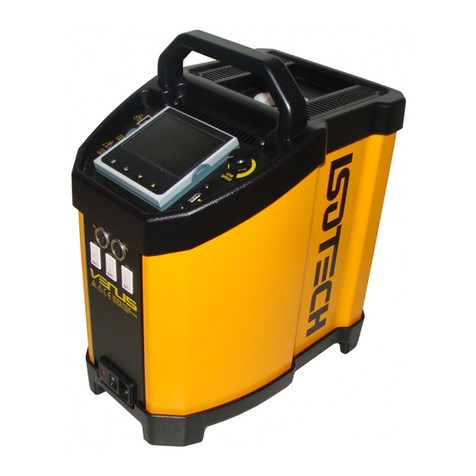
Isotech PEGASUS PLUS 1200 Series User manual

PEGASUS
PLUS
1200
HANDBOOK
ISSUE 5 - 01/05
Page 1 of 50
PEGASUS
PLUS
1200
This manual is issued under the authority of
Mr. J.P. Tavener, Managing Director
Isothermal Technology Limited
Pine Grov e, Southport
PR9 9AG, England
Tel: +44 (0) 1704 543830
Fax: +44 (0)1704 544799
w w w .isotech.co.uk
info@isotech.co.uk
The company is always willing to give technical advi ce and assistance where appropriate.
Equally, because of the programme of continual development and improvement we reserve the
right to amend or alter characteristics and design without prior notice. This publication is for
information only.

PEGASUS
PLUS
1200
HANDBOOK
ISSUE 5 - 01/05
Page 2 of 50
CONTENTS
PAGE DESCRIPTION
3,4 EMC Information
5Health & Safety Instructions
6Guarantee
7 Cautionary Note
8Introduction
9,10 Unpacking & Initial Inspection
11,12 Specification
13,14 Assembling the Insert
15 Operating the Controller
16,17,18,19 Operating the Indicator
20,21 Connecting a Current Transmitter (up to 20mA)
Testing Thermostats
22 Using the PC Interface
23,24 Using Cal Notepad
25 Diagnostics (Error Messages)
26,27 Pegasus
Plus
1200S, 1200B - Initial Testing
28 Pegasus
Plus
1200S, 1200B - Maintenance
29 Operating Procedures
30 Pegasus
Plus
1200B, 1200S - Checking Using the Temperature Indicated on
the Controller
31 Pegasus
Plus
1200B, 1200S - Calibration Using a Standard Thermometer
with External Indication
32 Pegasus
Plus
1200 S - Calibration Using a Standard Thermometer and the
Internal Indicator
33 Pegasus
Plus
1200S - Calibration Usi n g the Internal Indicator to Read a
Standard and Unknown Thermometers
34 Pegasus
Plus
1200S - Using the Indicator to Measure TemperaturesRemote
from the Furnace
35 Figure 1
36 Figure 2
37 Appendix 1 - Trouble Shooting
38 Appendix 2 - Accessories
39,40 Appendix 3 - Indicator Configuration
A - L Metal Block Tutorial

PEGASUS
PLUS
1200
HANDBOOK
ISSUE 5 - 01/05
Page 3 of 50

PEGASUS
PLUS
1200
HANDBOOK
ISSUE 5 - 01/05
Page 4 of 50
EMC INFORMATION
This product meetsthe requirementsof the European Directive on Electromagnetic Compatibility
(EMC) 89/336/EEC as amended by EC Directive 92/31/EEC and the Europe an L ow Vo ltage
Directive 73/25/EEC, amended by 93/68/EEC. To ensure emission compliance please ensure that
any serial communications connecting leads are fully screened.
The product meets the susceptibility requirements of EN 50082-1, criterion B.
Symbol Identification Publication Description
ISO3864 Caution
(Refer to Handbook)
I E C
417
C
a
ution, Hot Surface
ELECTRICAL SAFETY
This equipment must be correctly earthed.
This equipment is a Class 1 Appliance. A protective earth is used to ensure the conductive parts
can not become live in the event of a failure of the insulation.
The protective conductor of the flexible mains cable which is coloured green/yellow MUST be

PEGASUS
PLUS
1200
HANDBOOK
ISSUE 5 - 01/05
Page 5 of 50
connected to a suitable earth.
The blue conductor should be connected to Neutral and the Brown conductor to Live (Line).
Warning: Internal mains voltage hazard. Do not remove the panels.
There are no user serviceable parts inside. Contact your nearest Isotech agent for repair.
Voltage transients on the supply must not exceed 2.5kV.
Conductive pollution, eg. Carbon dust, must be excluded from the apparatus. EN61010 pollution
degrees 2.
The apparatu s ha s two input connectors for temperature sensors, see Figure 1. These inputs
are only suitable for either a thermocouple or resistance thermometer. No other sensor or signal
may be connected.

PEGASUS
PLUS
1200
HANDBOOK
ISSUE 5 - 01/05
Page 6 of 50
HEALTH AND SAFETY INSTRUCTIONS
1. Read all of this handbook before use.
2. Wear appropriate protective clothing.
3. Operators of this equipment should be adequately trained in the handling of hot and cold
items and liquids.
4. Do not use the apparatus for jobs other than tho se for which it was designed, ie. the
calibration of thermometers.
5. Do not h andl e the apparatus when it is hot (or cold), unless wearing the appropriate
protective clothing and having the necessary training.
6. Do not drill, modify or otherwise change the shape of the apparatus.
7. Do not dismantle the apparatus.
8. Do not use the apparatus outside its recommended temperature range.
9. If cased, do not return the apparatus to its carrying case until the unit has cooled.
10. T h ere are no user serviceable parts inside. Contact your nearest Isotech agent for
repair.
11. Ensure materials, especially flam m ab l e m aterials are kept away from hot parts of the
apparatus, to prevent fire risk.

PEGASUS
PLUS
1200
HANDBOOK
ISSUE 5 - 01/05
Page 7 of 50
GUARANTEE
This instrument has been manufactured to exacting standards and is guaranteed for twelve
months against electrical break-down or mechanical failure caused through defective material
or workmanship, provided the failure is not the result of misuse. In the event of failure
covered by this guarantee, the instrument must be returned, carriage paid, to the supplier for
examination and will be replaced or repaired at our option.
FRAGILE CERAMIC AND/OR GLASS PARTS ARE NOT COVERED BY THIS GUARANTEE
INTERFERENCE WITH, OR FAILURE TO PROPERLY MAINTAIN THIS INSTRUMENT MAY
INVALIDATE THIS GUARANTEE
RECOMMENDATION
The life of your ISOTECH Instrument will be prolonged if regular maintenance and cleaning to
remove general dust and debris is carried out.
We recommend the Pegasus Site to be re-calibrated annually.
Serial No:.............................................
Date:.....................................................
ISOTHERMAL TECHNOLOGY LTD.
PINE GROVE, SOUTHPORT
PR9 9AG, ENGLAND
TEL: +44 (0) 1704 543830/544611
FAX: +44 (0)1704) 544799
The company is always willing to give technical advice and assistance where appropriate.
Equally, because of the programme of continual development and improvement we reserve
the right to amend or alter characteristics and design without prior notice. This publication is
for information only.

PEGASUS
PLUS
1200
HANDBOOK
ISSUE 5 - 01/05
Page 8 of 50
CAUTIONARY NOTE
ISOTECH PRODUCTS ARE INTENDED FOR USE BY TECHNICALLY
TRAINED AND COMPETENT PERSONNEL FAMILIAR WITH
GOOD MEASUREMENT PRACTICES.
IT IS EXPECTED THAT PERSONNEL USING THIS EQUIPMENT
WILL BE COMPETENT WITH THE MANAGEMENT OF APPARATUS
WHICH MAY BE POWERED OR UNDER EXTREMES OF TEMPERATURE,
AND ARE ABLE TO APPRECIATE THE HAZARDS WHICH MAY
BE ASSOCIATED WITH, AND THE PRECAUTIONS TO BE TAKEN WITH,
SUCH EQUIPMENT.

PEGASUS
PLUS
1200
HANDBOOK
ISSUE 5 - 01/05
Page 9 of 50
INTRODUCTION
Th e Pegasus
Plus
1200 series consists of two models, the Basic (B) and Site (S). Both models
have been designed to be rugged and easily maintained.
By using a proprietary plug-in controller the total electronics package can be replaced in a few
minutes. As can be seen from the parts list, remarkably few components have been used, each
of which are easily removed and replaced. All models have a temperature range of 150 to
1200C.
Pegasus
Plus
1200 B - see page 33
This model pro vides an isothermal enclosure (metal block) in which thermometers and
thermostats can be checked against the temperature indicated on the temperature controller.
For traceable calibration a standard (reference) probe should be placed into the metal bl ocks
alongside the units under test.
The probe under test should be calibrated by comparison to the standard probe.
Pegasus
Plus
1200 S - see page 34
The S isagain similar to the B but thisunit hasthe addition of a digital temperature indicator. The
indicator is independent from the controller and can be programmed to work with a thermocouple
or industrial Pt 100 resistance thermometer.
T h i s combination of sensor and probe can be calibrated. Then the units under test can be
compared to the independent calibrated measuring systems allowing for traceable calibration.
The Pegasus
Plus
1200 Series represents the third generation of a ten year development program.
During which many customer improvement suggestions have been incorporated into the models.
Such suggestions have generally arisen from technical queries posed by equipmen t users,
therefore please consult with us if at all unsure with any aspect of our equipment.

PEGASUS
PLUS
1200
HANDBOOK
ISSUE 5 - 01/05
Page 10 of 50
The Pegasus
Plus
1200 models are part of a range of portable calibrators designed and made by
ourselves. Please contact us if you require more information about our other products.
UNPACKING AND INITIAL INSPECTION
Our Packing Department uses custom designed packaging to send out your unit, but
as accidents can still happen in transit, you are advised, after unpacking the unit, to
inspect it for any sign of shipping damage, and confirm that your delivery is in accordance with
the packing note. If you find any damage or that part of the delivery is missing notify us or our
agent, and the carrier immediately. If the unit is da m a ged yo u should keep the packing for
possible insurance assessment.
ELECTRICITY SUPPLY
Before connecting to th e el ectricity supply please familiarise yourself with the parts of the
handbook relevant to your model.
Your unit's supply voltage requirement is specified on a plate on the instrument along with the
serial number. All Pegasus
Plus
1200 instruments will work on an electricity supply frequency of
50Hz or 60Hz.
The apparatu s i s p ro vided with an approved power cord. If the plug is not suitable for your
location then the plug should be removed and replaced with an appropriate plug.
Take care to ensure the old plug is disposed safely.

PEGASUS
PLUS
1200
HANDBOOK
ISSUE 5 - 01/05
Page 11 of 50
The cable
i s colour
coded as
follows:
C
O L O U R
FU
NCTION
G r
ee n/yel lo
wEarth (Ground)
Brown Live (line)
Blue Neutral
Please ensure that your unit is correctly connected to the electricity supply.
A Residual Current Device sometimes called an RCD, ELCB or ground fault detector is included
with 230VAC Pegasus
Plus
1200 models.
It is fitted in line with the Pegasus
Plus
.

PEGASUS
PLUS
1200
HANDBOOK
ISSUE 5 - 01/05
Page 12 of 50
This RCD provides additional safety protection against fault conditions and must be used with
230VAC models.
THE APPARATUS MUST BE CORRECTLY EARTHED (GROUNDED)
The units on/off switch is located on the power inlet. Take care NOT to switch the unit off when
it is hot - allow to cool first.

PEGASUS
PLUS
1200
HANDBOOK
ISSUE 5 - 01/05
Page 13 of 50
SPECIFICATION
Voltage : 230VAC (or 115VAC) see ratings plate
Power : 2.5kW
Supply Frequency : 50/60Hz
Maximum Operating Temperature :1200°C
Minimum Operating Temperature: 150°C
Stability : ±0.05 to ±0.2°C
Calibration Volume : 33.5mm by 130mm
Standard Insert Hole Dimensions: :4 x 8mm
Insert Options : Special drill i ngs available to customer
requirements.
Dimensions (not including handle) : Height 302mm
Width 176mm
Depth 262mm
Weight : 8.50Kg

PEGASUS
PLUS
1200
HANDBOOK
ISSUE 5 - 01/05
Page 14 of 50

PEGASUS
PLUS
1200
HANDBOOK
ISSUE 5 - 01/05
Page 15 of 50
A full evaluation of the Pegasus 1200 is available contact the factory for availability

PEGASUS
PLUS
1200
HANDBOOK
ISSUE 5 - 01/05
Page 16 of 50
ASSEMBLING THE INSERT
The insert is connected to EARTH (Ground) by a metal spike, see diagram. It is essential this
connection is made.
TO ASSEMBLE THE INSERT
1. Ensure furnace is cool.
2. Slide the long ceramic insulator down the furnace tube so that the ti p of the spike
protrudes. (This can be checked by using a ruler or similar).
3. Carefully lower the insert using the extractor tool.
4. Unscrew extractor tool.
5. Finally add the smaller top ceramic insulator.

PEGASUS
PLUS
1200
HANDBOOK
ISSUE 5 - 01/05
Page 17 of 50

PEGASUS
PLUS
1200
HANDBOOK
ISSUE 5 - 01/05
Page 18 of 50
OPERATING THE
Plus
MODEL
FRONT PANEL LAYOUT
The Temperature Controller
The controller has a dual display, the upper display indicatesthe nominal block temperature, and
the lower display indicates the desired temperature or setpoint.
Altering the Setpoint
To change the setpoint of the controller simply use the UP and DOWN keys to raise and lower
the setpoint to the required value. The lower display changes to indicate the new setpoint.
Adv anced Controller Features
Setpoint Ramp Rate
The Pegasus
Plus
units incorporate an automatic setpoint ramp rate which limits the heat up rate
to a safe value which will not stress the ceramic furnace assembly.
After the setpoint is change the controller will automatically move the setpoint from the current
value to the target value at a preset rate.
The lower display will be seen to increment towards the target value.
The target (final) value may be inspected by momentarily pressing either the UP or DOWN key.

PEGASUS
PLUS
1200
HANDBOOK
ISSUE 5 - 01/05
Page 19 of 50
The setpoint ramp rate will also be seen when the unit is cooling although it does not increase
the cooling time.
Instrument Address
The controller has a configurable "address" wh i ch is used for PC communications. Each
instrument has an address, this all ows se veral instruments to be connected in parallel on the
same communications bus. The default value is 1. This address would only need to be changed
if more than one Dry Block is connected to the same PC port.
To check the Address value press the scroll key until the top display indicates,
Addr
The lower display will show the current value that can be modified with the UP and DOWN keys.
Monitoring the Indicator Status
A row of beacons indicate the controllers status as follows,
OP1 Heat Output
OP2 Cool Output (Only for models which operate below 0°C)
REM This beacon indicates activity on the PC interface
Units
Momentary pressing the Scroll key will show the controller units °C or °F.
The Temperature Indicator (Site (S) Models Only)
The site models include an electronic temperature indicator. The indicator can be configured for
the desired sensor type, and for custom calibration data. The custom calibration data can be set
ON or OFF.
Setting the Input Type
A 100 Ohm resistance thermometer can be connected to the PRT Connector or a thermocouple
may be connected to the miniature TC Connector.
Ensure that only a PRT or a TC is connected at any one time. If a PRT and TC are
connected simultaneously the indicator will read in error.

PEGASUS
PLUS
1200
HANDBOOK
ISSUE 5 - 01/05
Page 20 of 50
Check that any sensor placed into the Pegasus is suitable for the temperature range. Sensors
can be damaged if taken outside their normal operating limits.
The desired sensor type is easily set, press the Scroll key until the upper display indicates,
inPt
On the upper display. The lower display will show the current set sensor type,
J.tc J thermocouple
K.tc K thermocouple
L.tc L thermocouple
r.tc R thermocouple (Pt/Pt13%Rh)
b.tc B thermocouple (Pt30%Rh/Pt6%Rh)
n.tc N thermocouple
t.tc T thermocouple
S.tc S thermocouple (Pt/Pt10%Rh)
PL.2 PL 2 thermocouple
rtd 100platinum resistance thermometer.
T012 E thermocouple
Again the value can be modified with the UP and DOWN keys.
Enabling / Disabling Custom Calibration
Custom calibration allows the indicator to be programmed to suit a particular temperature sensor.
This allows the indicator to automatically show the true temperature, without having
to manually apply a correction.
When the Custom or User Calibration is active the indicator will show the REM beacon
lit continuously. The use of User calibration can make a significant difference to the
accuracy of the instrument, and this REM beacon provides a clear and continuous indication of
the calibration sta tu s. Isotech will configure and set user calibration when the Dry Block is
ordered with a temperature sensor.
To alter the calibration status press the Scroll key until the upper display shows,
Other manuals for PEGASUS PLUS 1200 Series
1
This manual suits for next models
2
Table of contents
Other Isotech Measuring Instrument manuals

Isotech
Isotech ICM 134 User manual

Isotech
Isotech 988 User manual

Isotech
Isotech PEGASUS 4853 ADVANCED Installation and operating instructions

Isotech
Isotech SLM 52N User manual

Isotech
Isotech SLA-1358 User manual

Isotech
Isotech PLTC-782 Mounting instructions

Isotech
Isotech Fast-Cal Series Operating instructions

Isotech
Isotech 2000 User manual

Isotech
Isotech VENUS 4951 BASIC User manual

Isotech
Isotech ICM 134 User manual