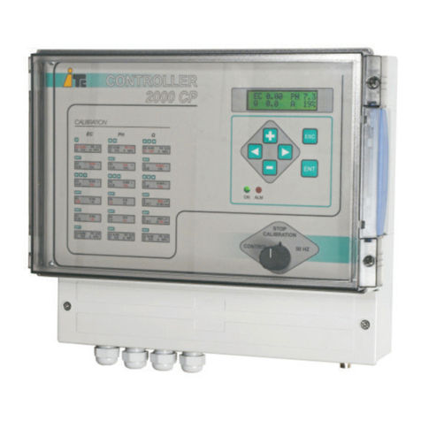
ITC WTRTEC Green User manual

WTRTEC
ENGLISH

CONTENTS
1. GENERAL DESCRIPTION 4
2. TRANSPORT AND HANDLING 4
3. TECHNICAL SPECIFICATIONS 5
4. OPERATION 6
4.1 Main screen and navigation 6
4.2 Setpoint conguration 7
4.3 Calibration 7
4.3.1 EC calibration 7
4.3.2 pH calibration 8
4.3.3 Flow rate calibration 8
4.4 Control conguration 9
4.4.1. Activation of the control 9
4.4.2. Advanced control conguration. PI control 10
4.5 Alarms 12
4.5.1 EC and pH alarms 12
4.5.2 Zero ow alarm 13
4.5.3 Flow detector alarm 13
4.6 Conguration of the register outputs 14
4.7 Conguration and monitor 14
4.7.1 Initial conguration (SET UP) 15
4.7.2 Communications settings 15
4.7.3 Information on the unit and monitor 16
5. INSTALLATION 17
5.1. Installation diagram 17
5.2. Wiring 18
5.3. Remote start/stop activation 19

To avoid personal injury risks and damage to the environment, and to ensure proper
equipment operation, personnel responsible for installing, commissioning and maintaining the
equipment must follow the instructions in this manual, with special attention to the detailed
recommendations and warnings. The specic instructions for the use of the chemicals to be
dosed must also be followed.
SAFETY INSTRUCTIONS
6. START UP AND ADJUSTMENT 20
7. MAINTENANCE 21
CE DECLARATION OF CONFORMITY 23
WARRANTY 23

4
Product description
1. GENERAL DESCRIPTION
WTRTEC Green is a high-precision pH, conductivity and proportional dosing controller that at the same
time is simple to install and operate. It is specially designed for processes such as fertigation, where
correction of pH and EC is needed.
The WTRTEC controller enables monitoring of ow, pH and EC, as well as their adjustment through
analogue and digital control outputs for dosing pumps. The analogue output (4-20 mA) control is specially
designed to provide in-line control adapted to ow rate changes (PIQ).
The WTRTEC enables remote monitoring and management by means of a mobile/web application.
A communications Gate (Ref. 01-006) is needed for this, which can be connected to the internet by
Ethernet or 3G/4G.
2. TRANSPORT AND HANDLING
The original packaging is designed to allow the equipment to be transported and stored without damage,
provided this takes place in dry, ventilated spaces away from heat sources.
Included in the packaging are:
- WTRTEC
- Instruction manual
INSTALLATION DIAGRAM
Communications
gate
(Ref. 01-006)
0
mS
2.5
PH
m3h 10.5
7.6
1
001
ºC 21.0
INTERNET

5
Product description
3. TECHNICAL SPECIFICATIONS
Power supply: 100-240 V 50-60 Hz. 10.8-14.4 VDC
Power: 6 W
IP65 protection
Housing material: ABS
Working temperature: 0 - 45 °C / 32 - 113 °F
Maximum relative humidity: 95% without condensation
Dimensions
Inputs
Flow meter 0.00-9999 m3/h / gph NPN isolated
Flow meter (power supply) 12 VDC (100 mA)
EC sensor 0.00-10.00 mS Isolated
EC temperature sensor 0.0 - 100ºC / 32.0 - 212 F NTC
pH sensor 0.00 - 14.00 Isolated
pH/EC temperature sensor 0.0 - 100ºC / 32.0 - 212 F PT100
Remote input ON/OFF 12-24 V AC/DC
Flow detector ON/OFF NPN isolated
Outputs
Relay 1 Alarm N.A. 230 V AC 1 A
Relay 2 Alarm N.A. 230 V AC 1 A
Relay 3 Alarm N.A. 230 V AC 1 A
Relay 4 Control N.A. 230 V AC 1 A
Relay 5 Control N.A. 230 V AC 1 A
4-20 mA 1 Control or record max. 520 Ohms
4-20 mA 2 Control or record max. 520 Ohms
Communications
RS485 port ModBus
mm inch
A229 9.02
B225 8.86
C119 4.69
A
B
C

6
Conguration
2.50 SP 2.00
032%
pH 7.60 SP 7.00
021%
m3h 10.5
CONFIG 21.3ºC
mS
2.50 SP 2.00
032%
pH 7.60 SP 7.00
021%
m3h 10.5
CONFIG 21.3ºC
mS
4. OPERATION
4.1 Main screen and navigation
Conrm
Exit without
conrming
Increase / decrease value,
and move up /down
Move left / right
ENT
ENT
ESC
0
mS
2.5
PH
m3h 10.5
7.6
1
001
ºC 21.0
0
mS
2.5
PH
m3h 10.5
7.6
1
001
ºC 21.0
Control
parameter 1
EC (or ow
rate)
Regulation
output
EC setpoint
value Move the cursor to select the following menu:
mS, pH, m3h or CONFIG, and enter with
ENTER
Warnings on the main screen:
Flashing reading: parameter alarm
Flashing regulation output: no device detected on the 4-20 mA output
Flashing regulation outputs (both): remote control deactivated, or no
device connected to the 4-20 mA outputs
Press ENTER to edit the setpoint
or move the cursor to enter the
following menu:
CAL: Calibration
CONTROL: control output
ALARM: alarms
REGISTER: output for register
pH regulation
output
Flow rate (or EC) reading
Access to the Conguration menu
Calibration menu
Alarm menu
Control menu
Register menu
Temperature
Cursor
Control
parameter 2
pH
mS
pH
pH
CAL
CONTROL
ALARM
REGISTER
SP 07.00
PH CAL.
Point 1 07.00
Point 2 04.00
Reading 07.23
PH CONTROL
CONTROL
PI CONTROL
PH ALARM
Rearm: Yes; No
Stop: pH; All; None
pH + 1.00 025 s
pH - 0.50 060 s
PH REGISTER
Out: 4-20 mA 2
4 mA: 00.00
20 mA: 14.00

7
Conguration
2.50 SP 2.00
032%
pH 7.60 SP 7.00
021%
m3h 10.5
CONFIG 21.3ºC
mS
2.50 SP 2.00
032%
pH 7.60 SP 7.00
021%
m3h 10.5
CONFIG 21.3ºC
mS
2.50 SP 2.00
032%
pH 7.60 SP 7.00
021%
m3h 10.5
CONFIG 21.3ºC
mS
ENT
ENT
ENT
ENT ENT
mS
pH
pH
CAL
CONTROL
ALARM
REGISTER
SP 07.00
4.2 Setpoint conguration
Conguration of the desired EC, pH or % values for the two channels for control through values or
setpoints.
Choose the control parameter for channel 1 between dosing by EC setpoint (mS) or by proportionality
value (%) of the product to be dosed with the irrigation water. Parameter selection is performed by
activating the control through the selected parameter’s Control menu. The parameter not selected for
control will remain as additional information and will be displayed in the lower right quadrant of the main
screen.
The second control channel is for pH.
To enter the setpoint:
m3h
CAL
CONTROL
ALARM
ALARM DETECTOR
REGISTER
0.20 %
SP
mS
CAL
CONTROL
ALARM
REGISTER
SP 02.00
change the value with the up/down
arrows and conrm with ENT
change the value with the up/down
arrows and conrm with ENT
change the value with the up/down
arrows and conrm with ENTER
If necessary, modify the value for the EC calibration standard using the up/down arrows. Insert the sensor
into the standard solution, wait until the sensor reading is stable and conrm with ENTER. If you are not
sure of the calibration, you can exit without conrming by pressing ESCAPE. The zero point is factory
calibrated.
4.3 Calibration
Calibration of the sensors used for EC, pH and ow. The calibration menu is in each parameter menu.
4.3.1 EC calibration
EC CAL.
ENT ENT
mS SP 02.00
CAL
CONTROL
ALARM
REGISTER
EC CAL.
Point 1 01.41 mS
Reading 01.37 mS
Point 1 01.41 mS
Reading 01.37 mS
m3h

8
Conguration
4.3.2 pH calibration
4.3.3 Flow rate calibration
ENT
ENT
ENT
pH
CONTROL
ALARM
REGISTER
SP 07.00
PH CAL.
Point 1 07.00
Point 2 04.00
Reading 07.23
PH CAL.
Point 1 07.00
Point 2 04.00
Reading 07.23
If necessary for pH calibration point 1, modify the buer value using the up/down arrows. Insert the sensor
into the point 1 buer, wait until the sensor reading is stable and conrm with ENTER.
Repeat the operation with the point 2 buer. Before putting the sensor in the point 2 buer, clean the
sensor with distilled water and dry it well (with tissue paper) to avoid contamination of the buer. If at any
time during the calibration process you are not sure of the calibration, you can exit without conrming by
pressing ESCAPE.
CAL
m3h 0.20 %
SP
CAL
CONTROL
ALARM
ALARM DETECTOR
REGISTER
Q CAL.
Type: Low Freq
K: 5.00 l/p
Time Q=0: 015 s
Select the type of ow meter:
- Low Freq:
Low frequency ow meter. Flow meters with pulse frequencies of between a minimum of 1 pulse every
200 seconds and a maximum of 30 pulses per second (30 Hz).
- K (l/p):
This type of ow meter requires entry of the conguration value the manufacturer indicates in litres/pulse.
- Time Q=0:
In these ow meters, which calculate the ow rate from the time between two consecutive pulses, a wait
time from which the ow rate is considered to be zero needs to be dened.
- High Freq:
High frequency ow meter for Hall eect or electromagnetic insertion ow meters with a maximum of
300 Hz (300 pulses per second).
- K-factor (p/l):
This type of ow meter requires entry of the K-factor (pulses/litre), corresponding to the diameter where it
is installed. This value is supplied by the manufacturer.

9
Conguration
4.4 Control conguration
4.4.1. Activation of the control
Activate control in the two parameters chosen for the regulation.
mS SP 02.00
CAL
CONTROL
ALARM
REGISTER
ENTENT
EC CONTROL
CONTROL
PI CONTROL
EC CONTROL
Control: OFF
Out: 4-20 mA 2
Limit out: 080%
Pump: 200 l/h
ENT
m3h 0.20 %
SP
CAL
CONTROL
ALARM
ALARM DETECTOR
REGISTER
Q CONTROL
Control: OFF
Out: 4-20 mA 2
Limit out: 080%
Pump: 200 l/h
ENTENT
pH SP 07.00
CAL
CONTROL
ALARM
REGISTER
PH CONTROL
CONTROL
PI CONTROL
PH CONTROL
Control: OFF
Out: 4-20 mA 1
Limit out: 080%
Pump: 20 l/h
For fertiliser dosing, choose between the options:
- Flow Rate control (proportionality):
Dosing will be regulated depending on the % value entered as the setpoint value, representing the
percentage of product ow rate dosed with respect to the main water pipe ow rate.
- EC control:
Dosing will be regulated automatically to adjust the conductivity reading to the value entered as the EC
setpoint.
- EC control with ow rate adjustment:
Activate the EC control and set the PEC value (%) in the PI Control menu to set an initial proportionality
value that the controller will regulate automatically to adjust to the EC setpoint.
For acid or base dosing for pH regulation:
- Control in pH:
Dosing will be regulated automatically to adjust the pH reading to the value entered as the pH setpoint.

10
Conguration
OFF
ON
5’
025% 50% 75% 10’
Salida al 100%
25% 50% 75%
Salida al 25%
OFF
ON
5’
025% 50% 75% 10’
25% 50% 75%
The regulating output will need to be selected for each control channel:
- Out:
Choose between the two 4-20 mA channels for analogue regulation or between the relay outputs for ON/
OFF regulation.
EC CONTROL
CONTROL
PI CONTROL
PH CONTROL
CONTROL
PI CONTROL
ENT
ENT
EC PI CONTROL
PIQ (PEC): 1.50
Kp:20
Ki:
30
T delay (s): 015
Q test: 00.00 m3h
PH PI CONTROL
PIQ (PpH)
030
Kp: 20
Ki:
30
T delay: 020 s
Q test: 00.00 m3h
Out = 4-20mA. For in-line process control. This is more precise regulation, which requires a pump with a
4-20 mA analogue input, such as a Dositec mA, Dostec AC or Dostec with variable frequency drive.
Out = Relay. For control in a recirculating tank. The regulating output establishes 5-minute cycles in
which the output will be ON for the proportional part of the time corresponding to PI adjustment.
- Limit out:
If a 4-20 mA output is used, this parameter allows you to limit the output value so as to limit the maximum
dosing pump ow rate.
- Pump:
Enter the rated dosing pump ow rate to record the dosed ow rate in the data logger.
4.4.2. Advanced control conguration. PI control
For adjustment of EC and pH, the control system operates using a PI algorithm. The setting parameters
for this control are in the PI CONTROL menu
- PIQ (PEC):
The PIQ control mode to adjust EC is a PI algorithm conditioned on the ow rate of water to be treated.
Initial dosing proportional to the water rate in % is set using the PEC parameter, and is subsequently
corrected by means of a PI approximation curve. This system combines the benets of proportional
dosing and EC setpoint dosing, ensuring stability

11
Conguration
of the EC reading, even with highly variable ow rates.
PEC=0 PI control. PIQ control disabled.
PEC= 0.01 - 2% Dosing will be proportional to the water ow at the % rate entered and with adjustment to
setpoint through a PI algorithm.
- PIQ (PpH):
The PIQ control mode to adjust pH is a PI algorithm conditioned on the ow rate of water to be treated.
Initial dosing proportional to the water rate is set using the PpH parameter, and is subsequently corrected
by means of a PI approximation curve. This system, which can only be activated with independent pumps
(type mA outlets for acid/alkaline dosing), ensures pH stability even with highly variable ow rates and
provides greater agility in reaching and maintaining the
setpoint.
PpH=0 PI control. PIQ control disabled.
PpH= 1 - 200 Acid dosing will be proportional to the water ow rate with setpoint adjustment by means
of a PI algorithm. The proportion is indicated by the PpH parameter and is referenced to 100,000 units of
water ow.
Example: For a ow rate of 200,000 l/h of water and a PpH = 1, proportional dosing of acid will be: (1 /
100,000) x 200,000 l/h = 2 l/h
The proportion needed to achieve a specic pH will depend not only on its nature and concentration, but
also on the nature of the water to be treated and the rest of the dosed products that can inuence this
parameter. The range PpH recommended to rapidly reach a pH and maintain it stable are detailed below.
The following tables for dierent acids are an approximation to the PpH value for these acids, depending
on the pH correction required (1 or 2 points of pH).
- Kp:
Proportional constant for PI adjustment. This parameter enables adjustment of the amount of device
response based on the dierence between the reading and the setpoint (Error). The default value
is normally correct for the majority of in-line controls. A value that is too high will produce reading
oscillations around the setpoint value. A value that is too low will produce a slow approach to the setpoint.
A1 point 2 points
60% 4-10 10-20
40% 8-15 15-30
10% 30-60 60-120
5% 60-110 120-200
A1 point 2 points
80% 3-8 8-15
50% 6-15 15-25
10% 30-60 60-120
5% 60-110 120-200
A1 point 2 points
90% 1-13 2-5
50% 2-5 4-10
10% 10-25 20-50
5% 20-50 40-100
Table for nitric acid
Note: Column "A" corresponds to the acid concentration
Table for phosphoric acid Table for sulphuric acid

12
Conguration
- Ki:
Integral PI adjustment. This parameter acts on the accumulated error and enables reading stabilisation
once the setpoint value has been achieved. It is only valid for in-line controls. For recirculating controls it
must be Ki=0.
- T delay (seconds):
T delay is the time between two consecutive controller orders to position the regulating output. For a
proper regulation, this time has to be greater than it takes fro a drop of dosed product to travel from the
injection point to the point where the pH or EC sensor is located.
- Q test:
Reference ow rate for T delay that allows for automatic adjustment of T delay with changes in water ow
rate, so that T delay is always at an optimal value. To keep T delay xed, leave Qtest = 0.
Example: In a 8" pipe through which water passes at 100 m3/h, the water speed is approximately 1 m/s.
If the distance between the injection point and the sensor is 10 metres, the installation delay time is 10
seconds.
The sensor will have a reaction time (approximately 10 seconds for the pH sensor), which must be added
to the installation delay time. Therefore, a T delay = 20 seconds should be set.
Bear in mind that if there are any lters between the injection point and the sensor, the calculation of 10
metres x 1m/s = 10 seconds will no longer be valid.
4.5 Alarms
4.5.1 EC and pH alarms
To set the alarms, enter the upper and lower tolerance values with respect to the value entered as the
setpoint and the time from which, with the reading outside tolerance range, the alarm must be activated. If
the value = 0, the alarm is disabled. The alarms will activate only if the Control is ON.
T delay
Injection
point Sensor
m/s

13
Conguration
mS SP 02.00
CAL
CONTROL
ALARM
REGISTER
EC ALARM
Reset: No
Stop: EC
mS + 2.00 025 s
mS - 1.50 060 s
ENT
pH SP 07.00
CAL
CONTROL
ALARM
REGISTER
PH ALARM
Reset: No
Stop: pH
pH + 1.00 025 s
pH - 0.50 060 s
ENT
mS+ 2.00: the alarm is activated when
the reading is 2.00 mS above the
setpoint value for 25 seconds
mS - 1.5: the alarm is activated when
the reading is 1.50 mS below the
setpoint for 60 seconds
pH + 1.00: the alarm is activated when
the reading is 1.00 above the setpoint
value for 25 seconds
pH - 0.5: the alarm is activated when
the reading is 0.50 below the setpoint
for 60 seconds
Reset: enables automatic alarm reset when the reading is back within the permissible values.
Stop: enables shutting down of the dosing control output for the alarmed control parameter, for all or none.
4.5.2 Zero ow alarm
An alarm can be set to warn that there is no ow in the main pipe.
If the value = 0, the alarm is disabled.
ENT
m3h 0.20 %
SP
CAL
CONTROL
ALARM
ALARM DETECTOR
REGISTER
Q ALARM
Stop: None
Q = 0 200 s
Reset: enables automatic alarm reset when the reading is back within the permissible values.
Stop: enables the dosing control outputs to be shut down.
4.5.3 Flow detector alarm
When an external sensor holder is used through which a water sample is made to pass, and this has a
ow detector, an alarm can be congured to warn in the event that no water sample reaches the external
sensor holder.
If the value = 0, the alarm is disabled.
o
Reset: N

14
Conguration
4.7 Conguration and monitor
CONFIG
SET UP
COMUNICATIONS
CHECK / MONITOR
mS 2.50 SP 2.00
032%
pH 7.60 SP 7.00
021%
m3h 10.5
CONFIG 21.3ºC
mS SP 02.00
CAL
CONTROL
ALARM
REGISTER
EC REGISTER
Out: 4-20 mA 2
4 mA: 00.00 mS
20 mA: 10.00 mS
ENT
pH SP 07.00
CAL
CONTROL
ALARM
REGISTER
PH REGISTER
Out: 4-20 mA 2
4 mA: 00.00
20 mA: 14.00
ENT
m3h 0.20 %
SP
CAL
CONTROL
ALARM
ALARM DETECTOR
REGISTER
Q REGISTER
Out: 4-20 mA 2
4 mA: 00.00
20 mA: 14.00
ENT
Reset: enables automatic alarm reset when the reading is back within the permissible values.
Stop: enables the dosing control outputs to be shut down.
4.6 Conguration of the register outputs
If any of the 4-20 mA analogue control outputs is unused, these can be used to be congured as outputs
for logging any sensor readings.
To do this, the output to be used needs to be selected and the 4 mA value related to the minimum sensor
reading, and the 20 mA value with the maximum reading.
ENT
Q ALARM DET
Stop: None
Q = 0 200 s
m3h 0.20 %
SP
CAL
CONTROL
ALARM
ALARM DETECTOR
REGISTER
o
Reset: N

15
Conguration
4.7.1 Initial conguration (SET UP)
ENT
CONFIG. COMMUNICATIONS
Node: 02
Baudrate: 1200
Parity: N
Stop bits:1
CONFIG
SET UP
COMUNICATIONS
CHECK / MONITOR
- Units:
Enables selection of the working units for the ow rate (litres or gallons) and temperature (Celsius or
Fahrenheit)
- pH Control:
To select whether the pH control uses an acid or a base
- pH Reading:
To enable or disable the pH reading, or set the reading manually
- Temp. Reading:
To enable or disable the temperature reading, or x a value manually. If using an ITC EC sensor, which
includes an internal temperature sensor, the reading will be the measure by this sensor.
- LCD auto:
Energy saving option that allowing for switching o of the screen if no action has taken place through the
menu in one minute
- EC Sensor:
Allows for selection of EC sensor type between the ITC sensor and a generic sensor with a cell constant
k=1
4.7.2 Communications settings
Setting the communications parameters via the RS485 port. Node, Baud Rate, Parity, and stop bit.
CONFIG. COMMUNICATIONS
Node: 02
Baudrate: 9600
Parity: N
Stop bits:1
CONFIG
SET UP
COMUNICATIONS
CHECK / MONITOR
CONFIG. SET UP
UNITS
PH CONTROL
PH READING
CONFIG. SET UP
ENT
FLOW Lenguage: ENG
TEMP.READING Reset params: Y
EC SENSOR LCD AUTO
FLOW
TEMP. READING
EC SENSOR

16
Conguration
4.7.3 Information on the unit and monitor
This screen displays information on the equipment and the raw value sensor, input and output readings.
CONFIG
SET UP
COMUNICATIONS
CHECK / MONITOR
Serial No. 9999
Soft. Vers. 1.07
Hard. Vers. 0.00
Model GREEN
INFO. UNIT >
mV pH -0.4
Temp 24.1
Ohms EC 0.22
Temp EC 24.1
Flow (Hz) 0.00
Pulse (Flow) ON
SENSORS >
ENT
Remote ON
Flow detector ON
Aux. Input CLOSE
INPUTS >
Relay 1 OPEN
Relay 2 OPEN
Relay 3 OPEN
Relay 4 OPEN
Relay 5 OPEN
4-20mA (1) 4.00
4-20 mA (2) 4.00
SENSORS >

17
Installation
5. INSTALLATION
A place protected from water, away from heat and direct sunlight must be chosen for installation.
5.1. Installation diagram
In-line dosing
Alternative system for obtaining a homogeneous mixture
Q
0
mS
2.5
PH
m3h 10.5
7.6
1
001
ºC 21.0
Device
Mixer
D
V (m/s)
v m/s
d
It must be ensured that the velocity in the branch
of diameter dis the same or somewhat higher than
that in the main pipe of diameter D. For this it needs
to comply with the following:
To maintain the velocity, v = V:
d = 0.7D
For v = 1.4 V
d = 0.6D
EC
pH

18
Installation
110-240 VAC power supply
12 VDC power supply
Remote ON/OFF input (can be activated
with 12-24 VAC/DC)
pH alarm output. Relay
EC alarm output. Relay
Flow rate alarm output. Relay
Control relay output. Relay 4.
Control relay output. Relay 5.
4-20 mA output. Output 1.
4-20 mA output. Output 2.
Temperature sensor input PT100.
Temperature sensor input NTC (ITC EC sensor).
Flow detector input.
Input for pH sensor (BNC connector)
Entry for Q ow rate sensor
Input for EC sensor
RS-485
5.2. Wiring
1
2
3
4
5
6
7
8
9
10
11
12
13
14
15
16
17
Cable glands for
general use
1
4
5
6
7
8
9
9
10
32
10
17
11
12
15
13
16
14 15
16

19
Installation
The probe cables must run through separate channelling.
Must be tted with a power supply circuit-breaking device
according to the EN-60204-1 standard.
A device for disconnection in case of emergency must be installed.
The equipment must be protected to prevent abrupt starts
5.3. Remote start/stop activation
2
100-240 VAC power supply
- External voltage-free signal
12-24 VDC power supply
- External voltage-free signal
- External 12-24 VAC/DC signal
-+
12-24V AC/DC
12V DC (IN)
-+
-- ++
2
100-240V AC
3
230V
-+
2
12-24V AC/DC
-+
3
3
-+
2
12V DC (IN)
-+
3

20
Installation
6. START UP AND ADJUSTMENT
1. Installation:
Install the equipment and connect the pumps (see Installing and Wiring)
2. Equipment calibration and conguration:
Calibrate the sensors (pH, ow meter, etc.) (see Calibration)
Congure the equipment:
- Setpoint
- Type of control
- Installation and equipment congurations
3. Check readings
Start up the installation and check that the sensor reading are correct
4. Check operation of the dosing pumps:
Use “Manual” activation if available
5. Determine “T delay” (time delay), according to the installation
6. Alarms:
Once proper operation of the installation has been conrmed, congure the alarms
See section 4.5
Table of contents
Other ITC Controllers manuals
Popular Controllers manuals by other brands

HERA
HERA DynamicController Assembly and operating instructions

BIFFI
BIFFI OLGA-H Installation, operation and maintenance manual

Aruba Networks
Aruba Networks 7210 installation guide

Faulhaber
Faulhaber MCDC2805 series instruction manual

Mastip
Mastip METICOM CTI Series user guide

Extron electronics
Extron electronics PC 101 Setup guide