manuals.online logo
Brands
  1. Home
  2. •
  3. Brands
  4. •
  5. ITC
  6. •
  7. Controllers
  8. •
  9. ITC VersiControl 22500-RGBW Series Configuration guide

ITC VersiControl 22500-RGBW Series Configuration guide

3030 Corporate Grove Dr. • Hudsonville • MI • 49426
Phone: 616-396-1355 • www.itc-us.com • [email protected] • DOC#: 710-00025 Rev F • 09/20/17
VersiControl RGBWSmart System Install Instructions
(Part #’s: 22500-RGB-XX & 22500-RGBW-XX)
Safety Instructions
• Disconnect power before installing, adding or changing any component.
• To avoid a hazard to children, account for all parts and destroy all packing materials.
• Do not install any luminaire assembly closer than 6” from any combustible materials.
• Positive (+) outputs require a fuse if the attached wire leads are not rated to handle the max current.
• This device complies with part 15 of the FCC rules. Operation is subject to the following two conditions:
- This device may not cause harmful interference
- This device must accept any interferences received, including interference that may cause undesired operation
For warranty information please visit www.itc-us.com
1. INSTALL: Determine the installation location for your control module. Make sure to consider the size of the module (7.5”L x 5”W x 1.5”H)
when determining your location. Note, it will require room for access and for wiring. Screw the controller in place using four M5 stainless
steel screws (not provided) sized appropriately for the substrate material used. Make sure when mounted, that the Bluetooth antenna is
not obstructed by metal objects.
1.5”
7.5”
5”
PARTS / TOOLS NEEDED:
VersiControl RGB
Smart System
Smart Pad
(Optional)
RGB Lighting
(Varies)
Mounting Screws x 4
(not provided)
Butt Splices
(not provided) Power Drill
2. CONNECT CONTROL PAD: If using the control pad (optional), insert
the connector on the control pad into the connector on the
module. Refer to control pad installation instructions for more
detailed information.
3. ZONE WIRE CONNECTIONS: Refer to the diagram below for refer-
ence when wiring the system in step 4. Note, there can be 16 or
20 zone wires coming out of the controller. Each wire has been
individually placed on the grommet of the assembly.
G WBR+
G WBR+
G +RBW
G +RBW
ZONE 1
ZONE 2
ZONE 3
ZONE 4
Bluetooth Antenna
3030 Corporate Grove Dr. • Hudsonville • MI • 49426
Phone: 616-396-1355 • www.itc-us.com • [email protected] • DOC#: 710-00025 Rev F • 09/20/17
4. WIRING DIAGRAM: Follow the wiring diagram below to wire the module to your system. Note: Maximum replacement fuse size is
25 amps.
Controller
Red - 12-24V DC IN (+)
Black - 12-24V DC IN (-)
(Max 20A)
Inputs
Outputs
Zone 1 - (Max 8A)
Zone 3 - (Max 8A)
Zone 4 - (Max 8A)
Zone 2 - (Max 8A)
Fuse
22500-RGB-XX
1
5
4
3
2
6
V(+)
V(-)
Shield
Signal Line
CAN (+)
CAN (-)
(+) White/Red
Red
Green
Blue
1
4
3
2
(+) White/Red
Red
Green
Blue
1
4
3
2
(+) White/Red
Red
Green
Blue
1
4
3
2
(+) White/Red
Red
Green
Blue
1
4
3
2
*Mating Connector: Deutsch DTM04-6P
*Mating Connector: Deutsch DT04-4P
Controller
Red - 12-24V DC IN (+)
Black - 12-24V DC IN (-)
(Max 20A)
Inputs
Outputs
(+) White/Red
Red
Green
Blue
White
Zone 1 - (Max 8A)
(+) White/Red
Red
Green
Blue
White
Zone 3 - (Max 8A)
(+) White/Red
Red
Green
Blue
White
Zone 4 - (Max 8A)
(+) White/Red
Red
Green
Blue
White
Zone 2 - (Max 8A)
Fuse
22500-RGBW-XX
1
5
4
3
2
6
V(+)
V(-)
Shield
Signal Line
CAN (+)
CAN (-)
*Mating Connector: Deutsch DTM04-6P
3030 Corporate Grove Dr. • Hudsonville • MI • 49426
Phone: 616-396-1355 • www.itc-us.com • [email protected] • DOC#: 710-00025 Rev F • 09/20/17
5. CUSTOMIZING YOUR SYSTEM: There are several features that can be selected using the four position dip switches on the back of
the control module. To adjust these switches, rst remove the four screws on the back.
Remove screws
MULTIPLE RGB CONTROLLERS ON SAME CAN
BUS NETWORK:
If you are using more than one controller on a
CAN network, you will need to adjust the CAN
address. Dip switch one and two are used to
select an address.
Switch 1 Switch 2 Address
OFF OFF 0 (Default)
ON OFF 1
OFF ON 2
ON ON 3
SELECT TO POWER UP IN THE ON OR OFF STATE:
Using dip switch four you can select if you
want the controller to power up in the OFF
state when power is applied, or in the ON
state once power is applied.
Switch 4 Power
OFF Power up OFF (default)
ON Power up ON
Dip switch
adjustment
6. DISABLE INPUT LINE (optional): The control module has the ability to turn off zones if an input line to the controller is activated.
Pin 4 of the 6-pin Deutsch connector contains this input line. If the disable line of the 6 pin Deutsch connector (pin 4) is held at the
input voltage (5-24 volts), Zones one and two will be turned off. This feature can be used if you want to deactivate the zone lights
on the outside of the boat when in motion. By default, only zones one and two are turned off. There is no effect on zones three
and four. You can adjust which zones are turned off via a CAN interface display system.
RESET PASS CODE:
If needed, dip switch three can be switched
on and then off to reset the Bluetooth pass
code.
Switch 3 Pass Code
OFF No change
ON Reset pass code

This manual suits for next models

1

Other ITC Controllers manuals

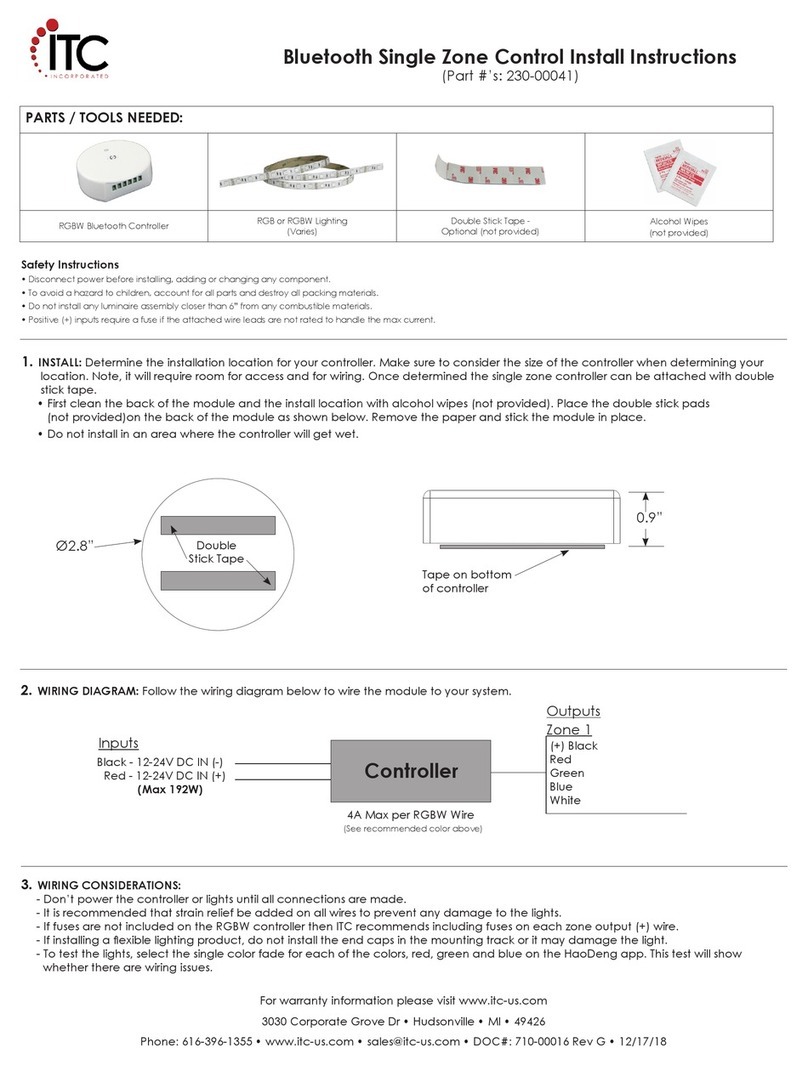
ITC 230-00041 Configuration guide

ITC

ITC 230-00041 Configuration guide

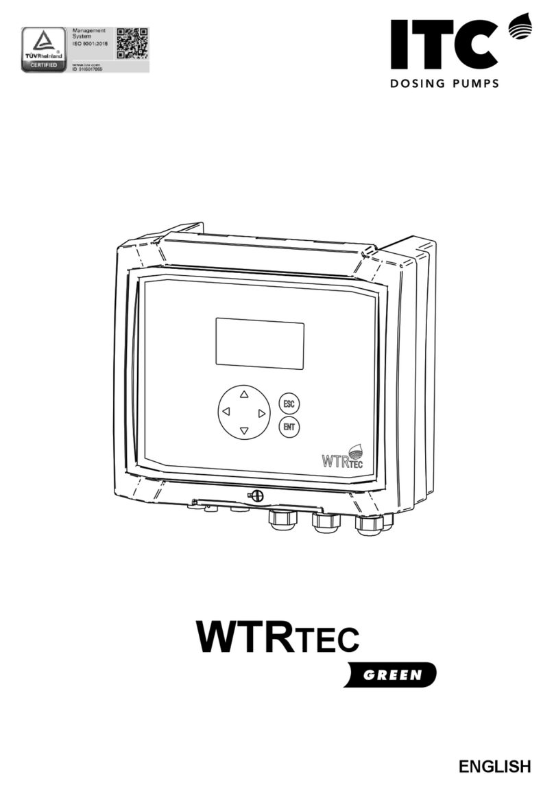
ITC WTRTEC Green User manual

ITC

ITC WTRTEC Green User manual

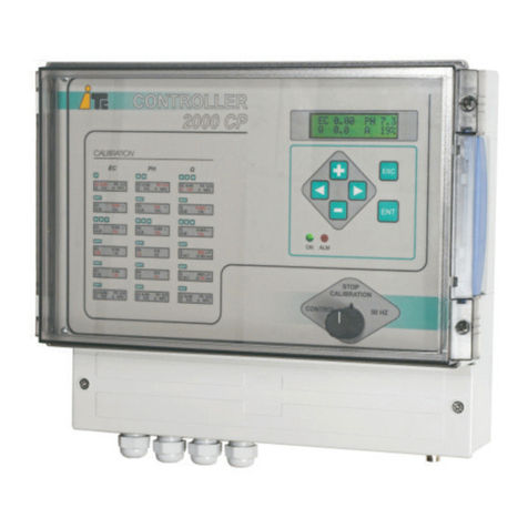
ITC COMPACT V 2000CP User manual

ITC

ITC COMPACT V 2000CP User manual

ITC VISIONS 3000 User manual

ITC

ITC VISIONS 3000 User manual

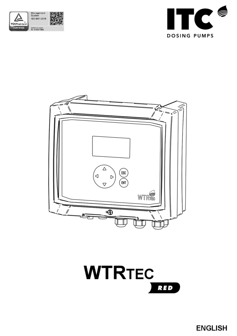
ITC WTRTEC RED User manual

ITC

ITC WTRTEC RED User manual

Popular Controllers manuals by other brands

Diamond RED07/35 quick reference

Diamond

Diamond RED07/35 quick reference

Ace TC100 Quick Start Instruction

Ace

Ace TC100 Quick Start Instruction

Arlight LT3200-350 quick start guide

Arlight

Arlight LT3200-350 quick start guide

Gavita Master EL2 user manual

Gavita

Gavita Master EL2 user manual

Behringer Eurolight BLM420 Technical specifications

Behringer

Behringer Eurolight BLM420 Technical specifications

Skope S4 EVO instruction sheet

Skope

Skope S4 EVO instruction sheet

Rockwell Automation Allen-Bradley CompactLogix 5370 L2 Series Product information

Rockwell Automation

Rockwell Automation Allen-Bradley CompactLogix 5370 L2 Series Product information

OXO Solano Pro instruction manual

OXO

OXO Solano Pro instruction manual

iNels RF KEY quick start guide

iNels

iNels RF KEY quick start guide

BRC Alta Operation

BRC

BRC Alta Operation

Siemens SINAMICS G Series manual

Siemens

Siemens SINAMICS G Series manual

rauland 2524 ChronoCom installation manual

rauland

rauland 2524 ChronoCom installation manual

Ingersoll-Rand INSIGHTqcx Product information

Ingersoll-Rand

Ingersoll-Rand INSIGHTqcx Product information

Lenz Digital plus LH101 operating instructions

Lenz

Lenz Digital plus LH101 operating instructions

Vera veraplus user manual

Vera

Vera veraplus user manual

SDJ FASTER 4 RGBW user manual

SDJ

SDJ FASTER 4 RGBW user manual

KNX GIRA manual

KNX

KNX GIRA manual

Pego VISION TOUCH THR User and maintenance manual

Pego

Pego VISION TOUCH THR User and maintenance manual

manuals.online logo
manuals.online logoBrands
  • About & Mission
  • Contact us
  • Privacy Policy
  • Terms and Conditions

Copyright 2025 Manuals.Online. All Rights Reserved.