ITI 60-620 User manual

Page 1
Superbus Energy Saver Module
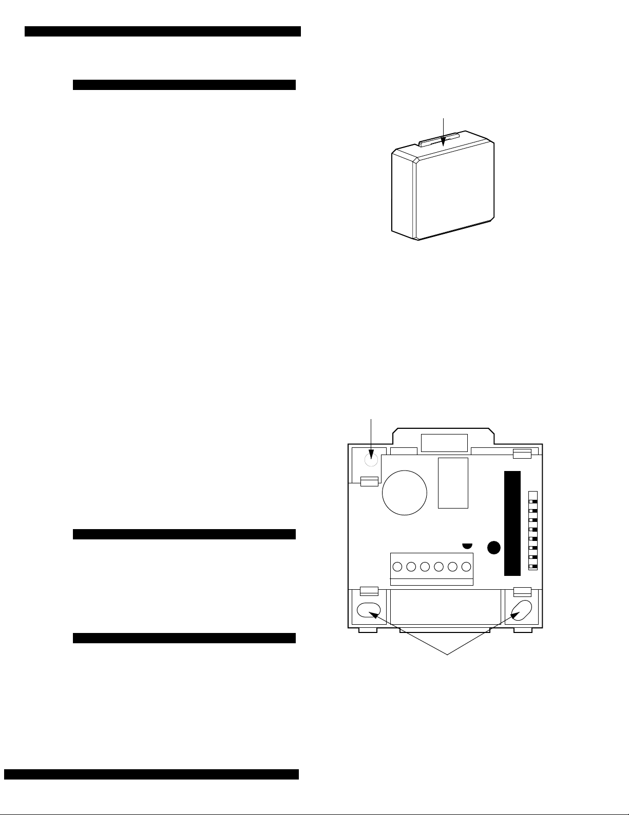
Figure 1 shows the main ESM components and Table 1
describes the main ESM components.
Figure 1. ESM Component Locations
Table 1. ESM Component Descriptions
ESM Component Function
Backup Freeze Stat Activates furnace if temperature
drops to 45°F (±6°F).
ESM Software Ver-
sion Label Identifies the installed software
version.
Unit Number DIP
Switch Determines the ID number of the
ESM on the bus.
Light-Emitting Diode
(LED) Flashes constantly to indicate nor-
mal communication to the panel
bus.
Temperature Sensor Monitors the premises temperature.
Terminal Strip Used for panel and HVAC thermo-
stat connections.
123456
8557G31A.DS4
BACKUP
FREEZE
STAT
LED
ESM SOFTWARE
VERSION LABEL
TERMINAL STRIP
UNIT NUMBER
DIP SWITCH
TEMPERATURE
SENSOR
Superbus Energy Saver
Module
Document Number: 466-1031 Rev. B
January 1997
Installation
Instructions
Product Summary
The Superbus Energy Saver Module (ESM) provides a
money-saving and convenient way to monitor and
control temperatures. The ESM uses low- and high-
temperature limits to save energy by overriding the
existing HVAC thermostat. When the ESM is on,
temperature limits determine when the heat or air-
conditioning turns on. When the ESM is off, the HVAC
thermostat controls heat and air-conditioning.
For example, if the thermostat is set for 68°F and the
ESM high limit is 80°F, the ESM prevents the air-
conditioner from turning on until the temperature reaches
80°F.
A temperature sensor monitors the temperature and
reports a freeze alarm to the panel if the temperature
drops below the set freeze temperature (default = 42°F).
A backup freeze stat provides additional protection by
activating the furnace if the temperature drops to 45°F
(±6°F).
60-620
8841G01A.DS4
Superbus Energy Saver Module
Page 2
Installation Guidelines
Use the following guidelines when installing the ESM:
νFor UltraGard™
systems, up to eight superbus
devices can be connected to the panel (Superbus
Alphanumeric Touchpad, HIM, ESM, etc.).
νEach superbus device must have a different unit ID
number.
νFor UltraGard systems, only one ESM can be
connected to a panel.
νThe ESM’s maximum current draw is 20 mA.
νDo not exceed the panel’s total power when using
panel power for bus devices and hardwired sensors
that require panel power (refer to the specific
panel’s installation instructions).
νUse 4-conductor, 22-gauge or larger stranded wire
from the ESM to the panel.
νUse 2-conductor, 22-gauge or larger stranded wire
from the ESM to the thermostat.
νInstall the ESM on an inside wall, next to or as
close as possible to the existing thermostat. This
keeps the temperature difference between the ESM
and the thermostat to a minimum.
νProgrammable thermostats that use a battery to keep
time and other programmed settings may lose time
and/or programmed settings when the ESM is
turned on. This can happen since the ESM relay is
interrupting the thermostat’s main power, forcing the
thermostat to rely on battery power to save time
and programmed settings. As a result, the thermostat
battery may need to be replaced more often,
depending on how often and how long the ESM is
turned on.
Tools Needed
νSmall pocket-size screwdriver
νScrews and anchors (included)
νDigital voltmeter
Installation
Installation consists of mounting the ESM (next to or as
close as possible to the existing thermostat) and wiring it
to the panel and existing HVAC thermostat.
To mount the ESM:
1. Press down on the top center of the cover and pull
it away from the base (see Figure 2). Set the cover
aside.
Figure 2. Removing the Enclosure Cover
CAUTION: You must be free of static electricity
before handling circuit boards. Wear
a grounding strap or touch a bare
metal surface to discharge static
electricity.
2. Place the ESM on the wall at the desired location
and mark the upper-left and lower-right mounting
holes (see Figure 3).
Figure 3. Mounting Hole Locations
3. Install anchors where studs are not present and
secure the ESM to the wall with the enclosed
screws.
PRESS DOWN
HERE
8857G46A.DS4
123456
MOUNTING HOLES
MOUNTING
HOLE
8557G29A.DS4

Superbus Energy Saver Module
Page 3
Wiring
Some thermostats control heating and cooling, others
control only heating. A heating/cooling thermostat uses
four wires and a heating-only thermostat usually has
two. The general color code for four-wire thermostats is
as follows:
Red: Power feed to thermostat
Green: Fan control
Yellow: Cooling
White: Heating
Note: If the thermostat wire colors are different than
those described above, contact a qualified HVAC
service person for wiring information about the
specific thermostat you are working with. Be sure
to give the service person the manufacturer’s
name and model number of the thermostat.
To wire the ESM to the UltraGard panel:
1. Turn off the panel power switch.
2. Disconnect the panel battery and unplug the power
transformer.
3. Turn off the thermostat and remove its cover.
4. Route a 4-conductor, 22-gauge or larger, stranded
wire from the ESM to the panel.
5. Connect terminals 3 thru 6 to the panel as shown in
Figure 4.
Figure 4. ESM Wiring Connections to the Thermostat
and UltraGard Panel Terminals
6. Route a 2-conductor, 22-gauge or larger, stranded
wire from the ESM to the thermostat.
To connect a four-wire thermostat:
1. Remove the red wire (or power feed) from the ther-
mostat and connect it to ESM terminal 1.
2. Connect a wire from ESM terminal 2, to the ther-
mostat terminal on the where the red wire (or
power feed) was connected.
To connect a two-wire thermostat:
1. Remove one of the wires from the thermostat and
connect it to ESM terminal 1.
2. Connect a wire from ESM terminal 2, to the termi-
nal on the thermostat where the original wire had
been connected.
Setting the ESM Unit ID Number
Before you power up the panel, you must set the unit ID
number on the ESM so that the panel recognizes the
device. Each bus device must have a different unit ID
number for successful communication and operation with
the panel.
To set the ESM unit ID number for UltraGard systems:
Locate the DIP switches on the ESM circuit board
(see Figure 1) and set them to the desired ID num-
ber, 0-7 (see Figure 5).
Note: Switches 1 thru 5 must remain in the OFF posi-
tion as shown in Figure 5.
Figure 5. ESM Unit ID DIP Switch Settings
12 13 14 15
6
12 3 4 5
ESM TERMINALS
ULTRAGARD
PANEL TERMINALS
THERMOSTAT
TO FURNACE
DC
OUT
BUS
A
BUS
B
GND
8557G30A.DS4
8557G32A.DS4
UNIT NUMBER 0
UNIT NUMBER 1
UNIT NUMBER 2
UNIT NUMBER 3
UNIT NUMBER 4
UNIT NUMBER 5
UNIT NUMBER 6
UNIT NUMBER 7
678
12345
678
12345
678
12345
678
12345
678
12345
678
12345
678
12345
678
12345

Superbus Energy Saver Module
Page 4
Power Up and Bus Communication
This section describes how to power up the panel and
the ESM and get them communicating with each other.
To power up the UltraGard panel and the ESM:
1. Verify that all wiring at the panel and the ESM are
correct.
2. Reconnect the panel battery and plug in the power
transformer.
3. Turn on the panel power switch.
4. Set the panel’s RUN/PROGRAM switch to
PROGRAM.
If the alphanumeric display reads 1-OFF and the 1
is flashing, you must enter the install code (4-digit
installer access code) to get the panel into the pro-
gram mode.
The alphanumeric display should read PROGRAM
MODE and the ESM LED should be flashing con-
tinuously, indicating successful communication to
the panel.
Note: If the LED is not flashing continuously, set the
RUN/PROGRAM switch to RUN and turn off the
panel power switch. Verify that all wiring is cor-
rect and that all bus devices are set with different
unit ID numbers.
Whenever the ESM unit ID number is changed,
you must turn off the panel power switch, turn it
back on, and then enter the program mode for
the panel and ESM to communicate successfully.
Setting the ESM SET TEMP
The SET TEMP programming command lets you adjust
the ESM temperature so it matches the house thermostat
reading. Refer to the specific panel’s installation
instructions for complete details.
Note: The ESM must be installed and powered up for a
minimum of 15 minutes before adjusting the ESM
temperature, to ensure consistent readings
between the ESM and house thermostat.
For best results, wait an hour before adjusting the
ESM temperature as described in the specific
panel’s
reference manual
.
Programming and Testing the ESM
For complete ESM programming and testing information,
refer to the specific panel’s installation instructions.
Specifications
Compatibility: UltraGard
Power Requirements: 12 VDC, 30 mA (maximum)
Dimensions: 2.60" x 2.60" x.90" (L x W x D)
Notices
This device complies with part 15 of the FCC rules. Operation is subject to the following
two conditions:
1) This device may not cause harmful interference.
2) This device must accept any interference received, including interference that may
cause undesired operation.
Changes or modifications not expressly approved by Interactive Technologies, Inc. can
void the users authority to operate the equipment
ITI is a registered trademark of Interactive Technologies, Inc. UltraGard is a trademark of
Interactive Technologies, Inc.
Other ITI Control Unit manuals

Popular Control Unit manuals by other brands

Festo
Festo Compact Performance CP-FB6-E Brief description

Elo TouchSystems
Elo TouchSystems DMS-SA19P-EXTME Quick installation guide

JS Automation
JS Automation MPC3034A user manual

JAUDT
JAUDT SW GII 6406 Series Translation of the original operating instructions

Spektrum
Spektrum Air Module System manual

BOC Edwards
BOC Edwards Q Series instruction manual

KHADAS
KHADAS BT Magic quick start

Etherma
Etherma eNEXHO-IL Assembly and operating instructions

PMFoundations
PMFoundations Attenuverter Assembly guide

GEA
GEA VARIVENT Operating instruction

Walther Systemtechnik
Walther Systemtechnik VMS-05 Assembly instructions

Altronix
Altronix LINQ8PD Installation and programming manual


