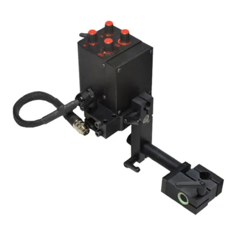
Itm GECKO User manual

BEFORE USE, ENSURE EVERYONE USING THIS MACHINE READS AND UNDERSTANDS
ALL SAFETY AND OPERATING INSTRUCTIONS IN THIS MANUAL .
Serial #............................................ Date of Purchase............................
OPERATOR’S MANUAL
GECKO
WELDING CARRIAGE
ul. Elewatorska 23/1, 15-620 Białystok, Poland
Phone: +48 85 678-34-95, Fax: +48 85 662-78-77
www.promotech.eu e-mail: info@promotech.eu
OPERATOR’S MANUAL
G
GE
EC
CK
KO
O
(
(H
HS
S)
)
WELDING CARRIAGE
Ver: 2.03 25/08/23

GECKO OPERATOR’S MANUAL
2www.itmtools.com.au
LIMITED WARRANTY
Industrial Tool & Machinery Sales (hereinafter referred to as ITMS) will, within twelve (12) months from the
original date of purchase, repair or replace any goods found to be defective in materials or workmanship.
This warranty is void if the item has been damaged by accident, neglect, improper service or other causes not
arising out of defects in materials or workmanship. This warranty does not apply to machines and/or components
which have been altered, changed, or modified in any way, or subjected to overloading or use beyond
recommended capacities and specifications. Worn componentry due to normal wear and tear is not a warranty
claim. Goods returned defective shall be returned prepaid freight to ITMS or agreed repair agent, which shall
be the buyer’s sole and exclusive remedy for defective goods. ITMS accepts no additional liability pursuant to
this guarantee for the costs of travelling or transportation of the product or parts to and from ITMS or the service
agent or dealer, such costs are not included in this warranty.
Our goods come with guarantees which cannot be excluded under the Australian Consumer Law. You are
entitled to replacement or refund for a major failure and to compensation for other reasonably foreseeable loss
or damage. You are also entitled to have the goods repaired or replaced if the goods fail to be of acceptable
quality and the failure does not amount to a major failure.
THE MANUFACTURER RESERVES THE RIGHT TO MAKE IMPROVEMENTS AND
MODIFICATIONS TO DESIGN WITHOUT PRIOR NOTICE.
PRODUCTS IMPORTED AND DISTRIBUTED NATIONALLY BY:
INDUSTRIAL TOOL & MACHINERY SALES
11 Eastern Service Road, Stapylton, QLD, 4207
F: 07 3287 1115 W: www.itmtools.com.au

GECKO OPERATOR’S MANUAL
3
www.itmtools.com.au
Contents
1. GENERAL INFORMATION ............................................................................................... 3
1.1. Application ................................................................................................................. 3
1.2. Technical data............................................................................................................ 3
1.3. Equipment included ................................................................................................... 4
1.4. Dimensions ................................................................................................................ 5
1.5. Design ....................................................................................................................... 6
2. SAFETY PRECAUTIONS.................................................................................................. 7
3. STARTUP AND OPERATION ........................................................................................... 9
3.1. Preparing ................................................................................................................... 9
3.2. Connecting to the welding circuits.............................................................................10
3.3. Positioning at the worksite ........................................................................................11
3.4. Operating ..................................................................................................................12
3.5. Changing the unit of speed .......................................................................................13
3.6. Troubleshooting ........................................................................................................14
4. MAINTENANCE ...............................................................................................................15
5. ACCESSORIES ...............................................................................................................16
5.1. Torch clamps ............................................................................................................16
5.2. Rods .........................................................................................................................17
5.3. Torch holders............................................................................................................18
5.4. Torch extension arm .................................................................................................20
5.5. Guide arms ...............................................................................................................21
5.6. Dual torch mount.......................................................................................................26
5.7. Auxiliary magnet blocks ............................................................................................27
5.8. Flexible guide set ......................................................................................................28
5.9. Guide adjustment tool ...............................................................................................30
5.10. Flexible trackway set...............................................................................................31
5.11. Magnetic units for flexible trackway .........................................................................34
5.12. Support for trackway with magnetic units ................................................................38
5.13. Vacuum unit ............................................................................................................39
5.14. Vacuum track system..............................................................................................40
5.15. Support for trackway with vacuum units ..................................................................41
5.16. 76 mm cross slide ...................................................................................................42
5.17. Cable anchor...........................................................................................................43
5.18. Display protection shield .........................................................................................43
5.19. Fall arrester.............................................................................................................44
5.20. Stainless steel wheels.............................................................................................45
6. 115–230 V WIRING DIAGRAM ........................................................................................46
7. 115–230 V HS WIRING DIAGRAM ..................................................................................47
8. 42 V WIRING DIAGRAM..................................................................................................48
9. 42 V HS WIRING DIAGRAM ............................................................................................49
10. DECLARATION OF CONFORMITY ...............................................................................50
11. WARRANTY CARD........................................................................................................51
1. GENERAL INFORMATION ........................................................................................ 4
1. 1. APPLICATION......................................................................................................... 4
1.2. TECHNICAL DATA...................................................................................................... 4
1.3. EQUIPMENT INCLUDED ........................................................................................... 5
1.4. DIMENSIONS ............................................................................................................. 6
1.5. DESIGN ...................................................................................................................... 7
2. SAFETY PRECAUTIONS ........................................................................................... 8
3. STARTUP AND OPERATION .................................................................................... 10
3.1. PREPARING .............................................................................................................. 10
3.2. CONNECTING TO THE WELDING CIRCUITS ......................................................... 12
3.3. POSITIONING AT THE WORK AREA ....................................................................... 13
3.4. OPERATING .............................................................................................................. 14
3.5. CHANGING THE UNIT OF SPEED ........................................................................... 15
3.6. TROUBLESHOOTING ............................................................................................... 16
4. MAINTENANCE ......................................................................................................... 17
5. ACCESSORIES .......................................................................................................... 18
5.1. TORCH HOLDERS, CLAMPS, AND RODS ............................................................... 18
5.2. TORCH EXTENSION ARM ........................................................................................ 20
5.3. GUIDE ARMS ............................................................................................................. 21
5.4. DUAL TORCH MOUNT .............................................................................................. 26
5.5. AUXILIARY MAGNET BLOCKS ................................................................................. 27
5.6. FLEXIBLE GUIDE SET .............................................................................................. 28
5.7. GUIDE ADJUSTMENT TOOL .................................................................................... 30
5.8. FLEXIBLE TRACKWAY SET ..................................................................................... 31
5.9. MAGNETIC UNITS FOR FLEXIBLE TRACKWAY ..................................................... 34
5.10. SUPPORT FOR FLEXIBLE TRACKWAY WITH MAGNETIC UNITS ........................ 38
5.11. VACUUM UNIT ........................................................................................................... 38
5.12. VACUUM TRACK SYSTEM ....................................................................................... 39
5.13. SUPPORT FOR FLEXIBLE TRACKWAY WITH VACUUM UNITS ............................ 40
5.14. 76 MM CROSS SLIDE ............................................................................................... 40
5.15. CABLE ANCHOR ....................................................................................................... 41
5.16. DISPLAY PROTECTION SHIELD .............................................................................. 42
5.17. FALL ARRESTER ...................................................................................................... 42
5.18. STAINLESS STEEL WHEELS ................................................................................... 43
6. PARTS LIST ............................................................................................................... 44
7. WIRING DIAGRAM .................................................................................................... 48

GECKO OPERATOR’S MANUAL
4www.itmtools.com.au
GECKO (HS)
This document is protected by copyrights.
Copying, using, or distributing without permission of PROMOTECH is prohibited.
3
1. GENERAL INFORMATION
1.1. Application
The GECKO (HS) is a welding carriage designed to make continuous butt and fillet
welds. The carriage allows MIG/MAG torches and is clamped with permanent mag-
nets.
Accessories allow using torches of a larger diameter and using two torches at the
same time. They also allow the carriage to move along outside edges, lap joints and
templates, walls that are low or have holes, and on ceilings, pipes, and tanks.
Using an optional flexible trackway set allows the carriage to move on a flexible
rail. You can clamp the rail to the surface by using magnetic units or by using vacuum
units and a vacuum track system.
The machine is designed for use by a professional operator only.
1.2. Technical data
GECKO
GECKO HS
Voltage
1~ 115–230 V, 50–60 Hz
1~ 42 V, 50–60 Hz
1~ 115–230 V, 50–60 Hz
1~ 42 V, 50–60 Hz
Power 20 W 20 W
Welding position
(according to EN
ISO 6947 and
AWS/ASME)
Horizontal
PA/1F/1G
PB/2F
PC/2G
PD/4F
PE/4G
PA/1F/1G
PB/2F
PC/2G
PD/4F
PE/4G
Vertical
PF/3G
–
Minimum path curve
radius
Outer
600 mm (23.6″)
600 mm (23.6″)
Inner
800 mm (31.5″)
800 mm (31.5″)
Torch type
MIG/MAG
MIG/MAG
Torch diameter
16–22 mm (0.63–0.87″)
Maximum torch reach
70 mm (2.8″)
70 mm (2.8″)
Maximum allowed
cable weight
Horizontal
work
8 kg (18 lbs) 8 kg (18 lbs)
Vertical work
6 kg (13 lbs)
–
Minimum workpiece thickness
4 mm (0.16″)
4 mm (0.16″)
Ground clearance 4 mm (0.16″) 4 mm (0.16″)
Horizontal pulling force
150 N
150 N
Vertical pulling force
100 N
–
Cross slide adjustment range
0–35 mm (0–1.38″)
(up-down, left-right)
0–35 mm (0–1.38″)
(up-down, left-right)
Guide arm adjustment range
0–170 mm (0–6.7″)
0–170 mm (0–6.7″)
Horizontal speed
0–110 cm/min (0–43.3 in/min)
5–220 cm/min (2–86.6 in/min)
Vertical speed
0–100 cm/min (0–39.4 in/min)
–
Weight
8 kg (18 lbs)
8 kg (18 lbs)

GECKO OPERATOR’S MANUAL
5
www.itmtools.com.au
GECKO (HS)
This document is protected by copyrights.
Copying, using, or distributing without permission of PROMOTECH is prohibited.
4
1.3. Equipment included
1
Welding carriage
1 unit
2
Torch holder
1 unit
3
Arc ignition cable
1 unit
4
4 mm hex wrench
1 unit
5
Box
1 unit
–
Operator’s manual
1 unit
1
2
3
4
5

GECKO OPERATOR’S MANUAL
6www.itmtools.com.au
GECKO (HS)
This document is protected by copyrights.
Copying, using, or distributing without permission of PROMOTECH is prohibited.
5
1.4. Dimensions
320 mm (12.6″)
240 mm (9.5″)
430 mm (17″)
280 mm (11″)

GECKO OPERATOR’S MANUAL
7
www.itmtools.com.au
GECKO (HS)
This document is protected by copyrights.
Copying, using, or distributing without permission of PROMOTECH is prohibited.
6
1.5. Design
Control panel
Arc ignition socket
Lug for fall arrester
Power switch
Guide arm
TEST
LED display
Speed knob
Arc ignition switch (TEST / O / I)
Direction switch (Left / O / Right)
Parameter indicator

GECKO OPERATOR’S MANUAL
8www.itmtools.com.au
GECKO (HS)
This document is protected by copyrights.
Copying, using, or distributing without permission of PROMOTECH is prohibited.
7
2. SAFETY PRECAUTIONS
1. Before use, read this operator’s manual and complete a training in occupational
safety and health.
2. Use only in applications specified in this operator’s manual.
3. Make sure that the carriage has all parts and they are genuine and not damaged.
4. Make sure that the specifications of the power source are the same as those spec-
ified on the rating plate.
5. Connect the carriage to a correctly grounded power source.
6. Do not carry the carriage by the cables, and do not pull them. This can cause dam-
age and electric shock.
7. Keep untrained bystanders away from the carriage.
8. Before each use, ensure the correct condition of the carriage, power source, cables,
plugs, sockets, control panel, and wheels.
9. Before each use, make sure that no part is cracked or loose. Make sure to maintain
correct conditions that can have an effect on the operation of the carriage.
10. Keep the carriage dry. Do not expose the carriage to rain, snow, or frost.
11. Keep the work area well lit, clean, and free of obstacles.
12. Do not use near flammable materials or in explosive environments.
13. Make sure that the rubber of the wheels is clean and not damaged.
14. Do not remove the cover of the wheels.
15. Remove objects attracted to the chassis by the magnet.
16. Transport and position the carriage by using the carrying handle.
17. Put the carriage so that four wheels are on the surface. Make sure that no contact
is between the surface and chassis.
18. Do not stay below the carriage that is put at heights.
19. Connect the cables only after you set the power switch to ‘O’.
20. Keep the sockets clean. Do not use high pressure during cleaning.
21. Install only MIG/MAG torches which diameter is the same as the diameter of the
torch holder.
22. Do not put the torch more than 70 mm (2.76″) outward from the left or right side of
the carriage.

GECKO OPERATOR’S MANUAL
9
www.itmtools.com.au
GECKO (HS)
This document is protected by copyrights.
Copying, using, or distributing without permission of PROMOTECH is prohibited.
8
23. Keep the torch cables away from the surface. Hang them to decrease the load
applied on the carriage. Use only cables whose weight is not more than 8 kg
(18 lbs) for horizontal work and 6 kg (13 lbs) for vertical work.
24. Do not work on curves with convex or concave radius less than specified in tech-
nical data.
25. Use the HS version of the carriage in horizontal positions only.
26. At heights, use a fall arrester not to let the carriage fall.
27. Use eye protection (helmet, shield, and screen), ear protection, gloves, and pro-
tective clothing. The clothing must not be loose.
28. Do not stop the carriage by hand. To stop, set the direction switch to ‘O’.
29. Do the maintenance only after you unplug the carriage from the power source.
30. Repair only in a service center appointed by the seller.
31. If the carriage falls, is wet, or has any damage, stop the work and immediately
send the carriage to the service center for check and repair.
32. Do not leave the carriage unattended during work.
33. If you are not going to use the carriage, remove it from the work area and keep in
a safe and dry place.

GECKO OPERATOR’S MANUAL
10 www.itmtools.com.au
GECKO (HS)
This document is protected by copyrights.
Copying, using, or distributing without permission of PROMOTECH is prohibited.
9
3. STARTUP AND OPERATION
3.1. Preparing
Transport the carriage to the work area by the carrying handle. Set to ‘O’ all switches
(power, direction, and arc ignition switch).
Fig. 1. View from the back
Knobs for precise torch
adjustment
Carrying handle
Levers to secure
the torch position and angle
Screw that secures the guide arm
Knob that secures the torch in the holder
Cross slide
Slide arm

GECKO OPERATOR’S MANUAL
11
www.itmtools.com.au
GECKO (HS)
This document is protected by copyrights.
Copying, using, or distributing without permission of PROMOTECH is prohibited.
10
You can change the torch adjustment range to the right by 22 mm (0.87”). Use 4 mm
hex wrench to detach the slide arm. Then, install it with four screws as shown in fig. 2.
Fig. 2. Changing the adjustment range to the right
You can change the torch adjustment range upward by 22 mm (0.87”). Use 4 mm hex
wrench to detach the cross slide. Then, install it with four screws as shown in fig. 3.
Fig. 3. Changing the adjustment range upward
Connect the carriage to the power source. Then, put the torch into the torch holder and
tighten with the knob.

GECKO OPERATOR’S MANUAL
12 www.itmtools.com.au
GECKO (HS)
This document is protected by copyrights.
Copying, using, or distributing without permission of PROMOTECH is prohibited.
11
3.2. Connecting to the welding circuits
The carriage can control two torches by using the arc ignition cable plugged into the
arc ignition socket. To do this, refer to the diagram from fig. 4 and connect one blue-
jacketed wire to one terminal of the welding circuit. Then, connect the other blue-jack-
eted wire to the other terminal of the same circuit. To control the second torch, connect
the green-jacketed wires to the terminals of the second welding circuit.
Fig. 4. Connecting the arc ignition cable to welding circuits
Make sure that the arc ignition cable is connected correctly. To do this, turn on the
power of the carriage, and then set the arc ignition switch to TEST. This should enable
the arc for a while.
Blue
Blue
Welding circuit 1
Green
Green
Welding circuit 2

GECKO OPERATOR’S MANUAL
13
www.itmtools.com.au
GECKO (HS)
This document is protected by copyrights.
Copying, using, or distributing without permission of PROMOTECH is prohibited.
12
3.3. Positioning at the work area
Put the guide arms so that the carriage is in constant contact with the workpiece. You
can set them by a constant step (interval adjustment), or continuously after you swap
them (continuous adjustment). To set them correctly when the carriage moves to the
left, use the 4 mm hex wrench to loosen the screw that secures the right guide arm.
Next, move out the right arm about 10 mm (0.4″) or one groove more than the left arm
(fig. 5), and then tighten the screw again.
When the carriage moves to the right, move out the left arm.
Fig. 5. Correct positioning of the guide arms
Interval adjustment
Continuous adjustment
Grooves
Swap the guide arms to change
between methods of adjustment
Movement direction
Lug for fall arrester
Moving out the right arm by one groove
You can install the roller assemblies at the
other end of the guide arms

GECKO OPERATOR’S MANUAL
14 www.itmtools.com.au
GECKO (HS)
This document is protected by copyrights.
Copying, using, or distributing without permission of PROMOTECH is prohibited.
13
To put the carriage closer to the workpiece, use the 4 mm hex wrench to remove the
roller assemblies. Next, install them at the other end of the guide arms, and then swap
the guide arms (fig. 5).
Loosen the levers to adjust the position and angle of the torch. Tighten the levers after
adjustment. Use two knobs at the cross slide to precisely set the torch position.
At heights, attach a fall arrester (not included) to a lug (fig. 5) to prevent fall of the
carriage. This will avoid possible injury to the operator in case the carriage loses the
clamping. Do not stay below the carriage that is put at heights.
3.4. Operating
To turn the carriage on, set the power switch to ‘I’. All display segments come on
(). Next, the software version shows ( ). If the speed unit is set to centimeters
per minute, shows. If the unit is set to inches per minute, shows. Next, the
carriage speed shows. Set the required value using the speed knob.
To control the torch through the carriage, set the arc ignition switch to ‘I’. Then the
welding arc ignites immediately after selecting the movement direction with the direc-
tion switch.
To go into the settings, press and hold the speed knob for 3 seconds. Select the pa-
rameter you want to set by turning the knob (tab. 1).
Parame-
ter
Value Description
0–5 s
[step: 0.5 s]
Carriage movement delay time.
When the direction switch is set to ◄ or ►:
= 0 s – the arc ignites and the carriage starts immediately,
> 0 s – the arc ignites and the carriage starts after the set time
(fig. 6).
0–5 s
[step: 0.5 s]
Arc out delay time.
When the direction switch is set to O:
= 0 s – the carriage stops and the arc goes out immediately,
> 0 s – the carriage stops and the arc ignites for the set time
(fig. 6).
Tab. 1. Parameters
To select the parameter, press the speed knob. Set the value by turning the knob. To
set, press the knob. To exit the settings, turn the knob until displays, then press
and hold the knob for 3 seconds. The settings are saved and used also at the next
startup of the carriage.

GECKO OPERATOR’S MANUAL
15
www.itmtools.com.au
GECKO (HS)
This document is protected by copyrights.
Copying, using, or distributing without permission of PROMOTECH is prohibited.
14
If the set carriage movement delay time ( ) or arc out delay time ( ) is more than
0 s, a parameter indicator ‘•’ shows next to the displayed carriage speed.
Use the direction switch to select the movement direction. The carriage starts work-
ing with the set parameters (fig. 6) and speed. You can adjust the speed at any time.
To stop the carriage, set the direction switch to ‘O’.
Fig. 6. Behavior of the carriage that controls the torch with the and parameters set
After the work is finished, use the power switch to turn off the carriage. Then, unplug
the carriage from the power source.
3.5. Changing the unit of speed
Before changing the unit of speed, set the power switch to ‘O’ to turn off the carriage.
To change the speed unit, press and hold the speed knob and set the power switch
to ‘I’ at the same time. The display shows the currently used unit. By turning the knob,
go to:
– to set the speed unit to centimeters per minute,
– to set the speed unit to inches per minute.
To select, press the speed knob. Then the carriage turns on and displays the set speed
unit.
Welding end
Direction switch
◄ or ►
Direction switch
O
Welding
start
The carriage moves
The welding arc ignites

GECKO OPERATOR’S MANUAL
16 www.itmtools.com.au
GECKO (HS)
This document is protected by copyrights.
Copying, using, or distributing without permission of PROMOTECH is prohibited.
15
3.6. Troubleshooting
Message
Problem
Solution
Display not fully on after powering. Contact service center for check
and repair.
Speed shown in centimeters per mi-
nute instead of inches per minute.
Refer to the section “Changing the
unit of speed.”
Speed shown in inches per minute in-
stead of centimeters per minute.
Refer to the section “Changing the
unit of speed.”
Direction switch not set to ‘O’ when
powering.
Set the direction switch to ‘O’. If the
message still shows, contact service
center for check and repair.
Shown during travel indicates a mal-
function.
Contact service center for check
and repair.
Arc ignition switch not set to ‘O’ when
powering.
Set the arc ignition switch to ‘O’. If the
message still shows, contact service
center for check and repair.
Motor overload. The carriage stops. Remove other objects that block the
carriage or its wheels.
Adjust the position of the cables so
that they do not block the carriage.
Use the welding cables whose weight
is not more than the maximum weight
specified in the technical data.
If this message still shows, contact
service center for check and repair.

GECKO OPERATOR’S MANUAL
17
www.itmtools.com.au
GECKO (HS)
This document is protected by copyrights.
Copying, using, or distributing without permission of PROMOTECH is prohibited.
16
4. MAINTENANCE
Every day:
1. Clean the chassis and wheels.
2. Clean the rollers of the guide arms. Make sure that the rollers turn freely.
3. Clean the torch nozzle and replace if damaged.
Every month:
1. Make sure that the knob and the switches work as intended. Replace if they are
loose or damaged.
2. Examine cables and cords and replace if damaged.
3. Tighten screws if loose.

GECKO OPERATOR’S MANUAL
18 www.itmtools.com.au
GECKO (HS)
This document is protected by copyrights.
Copying, using, or distributing without permission of PROMOTECH is prohibited.
17
5. ACCESSORIES
5.1. Torch holders, clamps, and rods
Short rod torch holder with clamp 16–22 mm
Part number:
UCW-0754-07-00-00-0
Quick-release short rod torch holder with clip 16–22 mm
Part number:
UCW-0523-84-00-00-0
Short rod torch holder with clip 16–22 mm
Part number:
UCW-0476-27-00-00-0
Short low rod torch holder with clip 16–22 mm
Part number:
WAP-L4090
Long rod torch holder with clamp 16–22 mm
Part number:
UCW-0752-07-00-00-0

GECKO OPERATOR’S MANUAL
19
www.itmtools.com.au
GECKO (HS)
This document is protected by copyrights.
Copying, using, or distributing without permission of PROMOTECH is prohibited.
18
Long rod torch holder with clip 16–22 mm
Part number:
UCW-0466-22-00-00-0
Torch clamp 16–22 mm
Part number:
WAP-G2090
Torch clip 16–22 mm
Part number:
WAP-G2160
Torch clamp 22–35 mm
Part number:
WAP-L4040
Short rod
Part number:
WAP-G2050
Long rod
Part number:
WAP-L4030

GECKO OPERATOR’S MANUAL
20 www.itmtools.com.au
GECKO (HS)
This document is protected by copyrights.
Copying, using, or distributing without permission of PROMOTECH is prohibited.
19
5.2. Torch extension arm
Increases the reach of the torch. Use the 4 mm hex wrench to remove the M5x10
screws that attach the cross slide. Next, use the same screws to attach the cross slide
at the end of the arm as shown in the figure. Then, use M5x16 screws to attach the
arm to the carriage.
Part number:
WA-G2020
M5×10
M5×16
Other manuals for GECKO
1
Table of contents
Other Itm Welding System manuals
Popular Welding System manuals by other brands

Weldability Sif
Weldability Sif Sifweld Evolution TS320ACDC Operation manual

Elektra Beckum
Elektra Beckum 170 - 230 Amp Models Operating instruction

Miller
Miller 300577001 owner's manual

Luna
Luna WM 1605 F manual

Strata
Strata ADVANCECUT 45 operating instructions

Lincoln Electric
Lincoln Electric HANDY MIG IM756-A Operator's manual