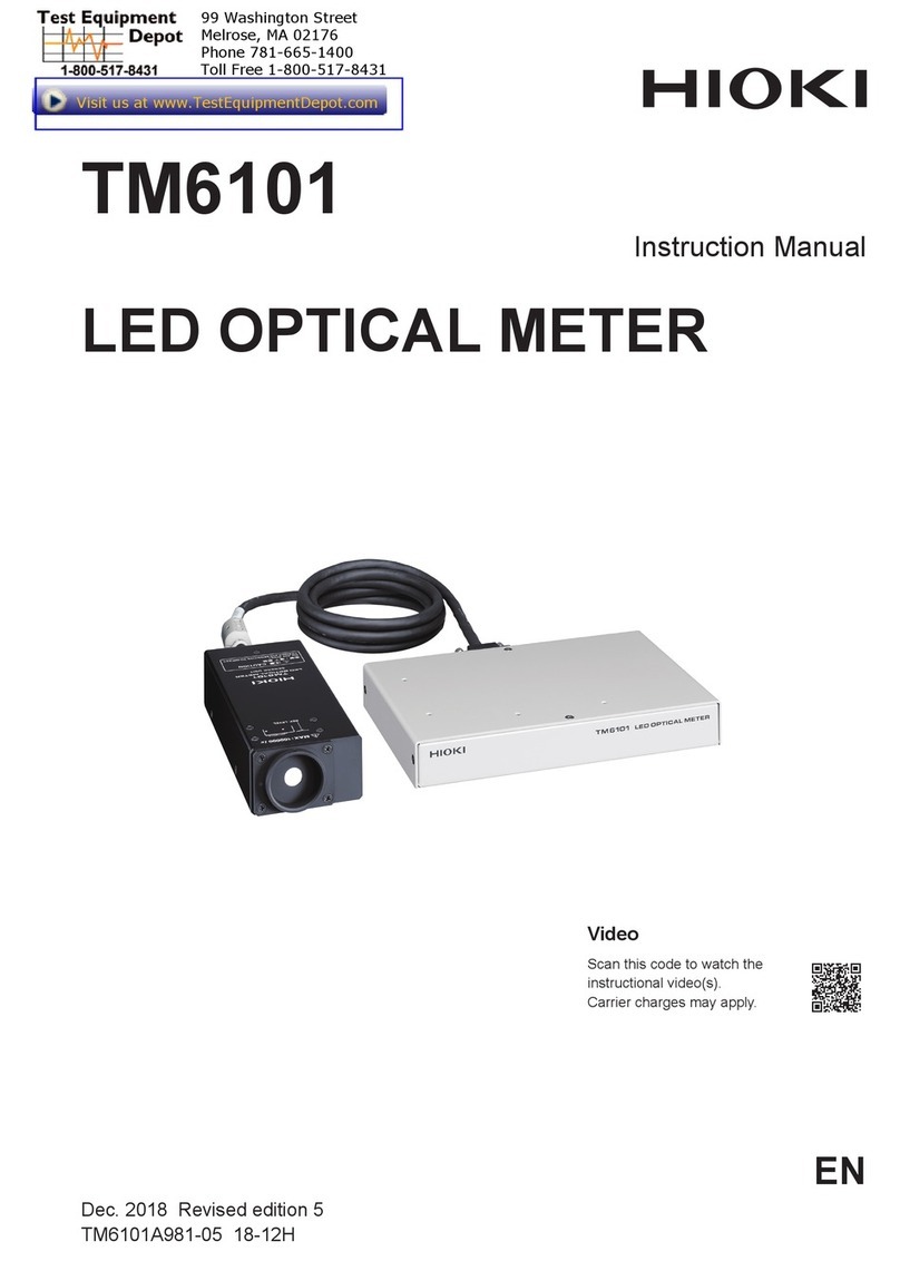
Hioki CHT3548 User manual

CHT3548
User’s Manual
RESISTANCE METER
2015-4-15
Hope Electronics Technology Manual Edition V1.0

Hope Electronics Technology Manual Edition V1.0 2
Contents
Introduction .......................................................................................................................4
Checking Package Contents..........................................................................................4
Safety Notes .....................................................................................................................5
Usage Notes.....................................................................................................................6
Chapter 1 Overview......................................................................................................9
1.1Overview and Features...........................................................................................9
1.2 Component Names and Operation Overview............................................... 10
1.3 Screen Layout....................................................................................................... 14
1.4 Checking the Measurement Target................................................................. 18
1.5 Dimension.............................................................................................................. 19
Chapter 1 Preparing for Measurement...................................................................... 20
2.1 Attaching the Strap.............................................................................................. 20
2.2 Loading or Replacing the Batteries................................................................ 21
2.3 Connecting the Test Leads............................................................................... 23
2.4 Turning the Power On/Off.................................................................................. 23
2.5 Pre-measurement Inspection............................................................................ 27
Chapter 3 Basic Measurement ................................................................................... 28
3.1 Setting the Measurement Range...................................................................... 28
3.2 Connecting the Test Leads to the Measurement Target........................... 30
3.3 Reading the Measured Value............................................................................ 31
Chapter 4 Customizing Measurement Conditions................................................... 36
4.1 Using Zero Adjustment ...................................................................................... 36
4.2 Stabilizing Measured Values (Averaging Function)................................... 40
4.3 Compensating for Thermal Effects (Temperature Correction (TC))....... 41
4.4 Compensating for Thermal EMF Offset (Offset Voltage Compensation
Function: OVC Function)................................................................................................ 43
4.5 Setting the Delay Time for Measurement (Delay Function)...................... 44
4.6 Switching the Measurement Current (In the 300m Range).................... 46
Chapter 5 Judgment and Conversion Functions ..................................................... 48
5.1 Judging Measured Values (Comparator Function)..................................... 48
5.2 Performing Temperature Rise Test (Temperature Conversion Function
(T)) ..................................................................................................................................... 54
5.3 measuring conductor length (length conversion function)...................... 55
Chapter 6 Panel Save and Load (Saving and Loading Measurement................. 58
6.1 Save the measurement conditions (Panel save function) ........................ 58
6.2 Reads the measurement conditions (panel reading function)................ 59
6.3 Clearing the Contents of a Panel..................................................................... 59
Chapter 7 Memory function......................................................................................... 61
7.1 Press any timing to save (manual storage).................................................. 63
7.2 After stable measurement values automatically save............................... 64
7.3 save at regular intervals (interval memory function)................................. 65
7.4 Display saved measurement data (stored display)..................................... 67
Hope Electronics Technology Manual Edition V1.0 3
7.5 Delete saved measurement data (clear memory)........................................ 68
7.6 The saved measurement data read into the computer.............................. 69
Chapter 8 System Settings.......................................................................................... 71
8.1 confirmation screen displays the date and time......................................... 71
8.2 calibration clock................................................................................................... 71
8.3 initialized (reset)................................................................................................... 73
Chapter 9 Appendix...................................................................................................... 74
Appx. 1 block diagram .............................................................................................. 74
Appx. 2 Four-Terminal (Voltage-Drop) Method................................................... 75
Appx. 3 on DC mode and AC mode....................................................................... 77
Appx. 4 on temperature compensation (TC)....................................................... 78
Appx. 5 on temperature conversion function ( T) ........................................... 80
Appx. 6 Effect of Thermoelectromotive Force (Thermal EMF)....................... 81

Hope Electronics Technology Manual Edition V1.0 4
Introduction
Thank you for purchasing the HIOKI RM3548 Resistance Meter. To obtain
maximum performance from the product, please read this manual first, and keep
it handy for future reference.
Registered trademarks
Windows and Excel are registered trademarks of Microsoft Corporation in
the United States and/or other countries.
Checking Package Contents
When you receive the instrument, inspect it carefully to ensure that no
damage occurred during shipping. In particular, check the accessories, panel
switches, and connectors. If damage is evident, or if it fails to operate according
to the specifications, contact your authorized Hioki distributor or reseller.
When transporting the instrument, use the same packaging materials used
for the delivery to you.
Check the package contents as follows
No.
Item Quantity
1 3548 Resistance Meter 1
2 User’s Manual 1
3 CD 1
4 USB Cable 1
5 9363A Test Clip 1
6 9705 Temperature Sensor 1
7 Strap 1
8 Alkaline battery 1
9 Carrying Bag 1
3548ResistanceMeter CarryingBag
9367Alkaline battery
9366TemperatureSensor 9363ATestClip

Hope Electronics Technology Manual Edition V1.0 5
Safety Notes
The instrument is designed to conform to IEC 61010 Safety Standards, and
has been thoroughly tested for safety prior to shipment. However, using the
instrument in a way not described in this manual may negate the provided safety
features.
Before using the instrument, be certain to carefully read the following safety
notes.
Note
Mishandling during use could result in injury or death, as wellas damage to
the instrument. Be certain that you understand the instructions and precautions
in the manual before use.
Notation
This manual contains information and warnings essential for safe operation
of the instrument and for maintaining it in safe operating condition. Before using
the instrument, be certain to carefully read the following safety notes.
Indicates very important message in this manual. When the symbol is
printed on the instrument, refer to a corresponding topic in the Instruction
Manual.
indicates DC (direct current)
indicates afuse
indicates earth terminal

Hope Electronics Technology Manual Edition V1.0 6
In this manual, the risk seriousness and the hazard levels are classified as
follows.
Indicates an imminently hazardous situation that will result in death or
serious injury to the operator.
Indicates a potentially hazardous situation that will result in death or
serious injury to the operator.
Indicates a potentially hazardous situation that may result in minor or
moderate injury to the operator or damage to the instrument or
malfunction.
Indicates functions of the instrument or relative suggestion of a
correct operation.
Accuracy
We define measurement tolerances in terms of f.s. (full scale), rdg. (reading)
and dgt. (digit) values, with the following meanings:
f.s. (Maximum display value)
This is usually the maximum display value. In the instrument, this
indicates the currently used range.
rdg.
(Reading or displayed value)
The value currently being measured and indicated on the measuring
instrument.
dgt.
(Resolution)
The smallest displayable unit on a digital measuring instrument, i.e.,
the input value that causes the digital display to show a “1”.
Usage Notes
Installation environment
lOperating temperature
0°C to 40°C 80%RH or less (no condensation) and humidity ranges
lStorage temperature

Hope Electronics Technology Manual Edition V1.0 7
-10°C to 50°C 80%RH or less (no condensation) and humidity ranges
Installing the instrument in inappropriate locations may cause a malfunction
of instrument or may give rise to an accident. Avoid the following locations.
lExposed to direct sunlight or high temperature
lExposed to corrosive or combustible gases
lExposed to water, oil, chemicals, or solvents
lExposed to high humidity or condensation
lExposed to a strong electromagnetic field or electrostatic charge
lExposed to high quantities of dust particles
lNear induction heating systems (such as high-frequency induction
lheating systems and IH cooking equipment)
lSusceptible to vibration
Checking before use
Before using the instrument the first time, verify that it operates normally to
ensure that no damage occurred during storage or shipping. If you find any
damage, contact your authorized Hopetech distributor or reseller.
Before using the instrument, check that the coating
of the test leads or cables are neither ripped nor torn and
that no metal parts are exposed. Using the instrument
under such conditions could result in electrocution.
Contact your authorized Hopetech distributor or reseller
in this case
Handling Precautions
Do not modify, disassemble, or repair the
instrument. This may result in fire, electric shock
accident, or injury.
Do not place the instrument on an unstable or
slanted surface. It may drop or fall, causing injury or
instrument failure.
To avoid corrosion and/or damage to the
instrument due to battery leakage, remove the
batteries from the instrument if it is to be kept in
storage for an extended period.
Be sure to turn the power off after using it.

Hope Electronics Technology Manual Edition V1.0 8
Measurement precautions
To avoid electric shock accident and short
circuit, please operate the instrument as following:
Do not allow the instrument to get wet, and do
not use it with wet hands. This may cause electric
shock accident.
Do not modify, disassemble, or repair the
instrument. This may result in fire, electric shock
accident, or injury.
Do not place the instrument on an unstable or
slanted surface. It may drop or fall, causing injury or
instrument failure.
To avoid any damage to the instrument, avoid
any vibration or shock during transport or handling.
Especially, be careful not to drop or fall the
instrument which will cause shock.
To avoid any damage to the instrument, do not
input voltage or current to any measurement, TC
terminals, or EXPORT terminals.
Handling leads and cables
To avoid electrical shock accident, do not short
test leads where
voltage is applied.
Do not use any test lead or temperature sensor
other than the ones specified by our company. It
may result in inaccurate measurement due to poor
contact or other reasons.
To avoid damaging the cables, do not bend or
pull the base of cables and the leads.
The ends of pin type leads are sharp. Be careful
to avoid injury.
Be careful not to allow contact between the lead
wire and the heat generating portion.

Hope Electronics Technology Manual Edition V1.0 9
Simple temperature rise test (for temperature estimation during power stop)
lTemperature conversion and interval measurement functions
lSupports copying of measurement data file from the instrument memory to the
PC
.
Well-designed instrument shaped for measuring without taking your hands and
eyes off the target, making it ideal for maintenance and large product
measurement
lStrap-attachable portable type
lStandard auto-memory and auto-hold, and optional L2105 LED Comparator
Attachment
Highly reliable specifications implemented in a compact, light-weight body
l35,000-dgt. high resolution
l0.1 Ω resolution at 1 A measurement current
Chapter 1 Overview
1.1Overview and Features
The CHT3548 employs the four-terminal method to highly accurately
measure the DC resistance of measurement targets including motor and
transformer windings, and welding, PC board patterns, fuses, resistors, and
materials such as conductive rubber. The instrument allows temperature
correction and so is especially suitable for measurement targets whose
resistance values change with temperature.

Hope Electronics Technology Manual Edition V1.0 10
1.2 Component Names and Operation Overview
Front Panel
Rear Panel
Rear panel

Hope Electronics Technology Manual Edition V1.0 11
Key Description
[ COMP] key
Comparator: oFF — ON (ABS mode) — ON (REF%
mode).
[BEEPSET] key (press and hold)
Judgment sound: oFF — Hi — in — Lo — Hi-Lo —
ALL1 — ALL2.
[PANEL] key
Panel load: Changes the panel No. “PrSEt” initializes
the measurement conditions.
[SAVE/CLEAR] key (press and hold)
Saves and clears panels: SAvE — CLr
[TC/ΔT] key
Temperature correction/conversion function: oFF —
TC —ΔT.
[LENGTH] key (press and hold)
Length conversion function: oFF — ON.
[AVG] key
Averaging function: oFF — 2 — 5 — 10 — 20.
[OVC] key (press and hold)
Offset voltage compensation (OVC) function: oFF —
oN
.
[MODE] key
Switches memory hold mode: oFF — A.HOLD
(auto-hold) → A.HOLD,A.MEMORY (auto-memory) →
INTERVAL (interval function).
[] key
Moves to a different digit of the setting.
[DELAY] key (press and hold)
Delay function: PrSEt (factory default) — 10 ms — 30
ms — 50 ms — 100 ms — 300 ms — 500 ms — 1000 ms.
[]key
Moves to a different digit of the setting.
[M.BLOCK SEL] key (press and hold) (p. 76)
Selects a memory block: A — b — C — d — E — F —
G
— H — J — L.
[▲ ]key
Changes values and items.
[VIEW] key (press and hold)
Toggles the display: Temperature — no indicator —
memory number.
(MEMORY No.)

Hope Electronics Technology Manual Edition V1.0 12
[▼]key
Changes values and items.
[DATE] key (press and hold)
Displays the date and time confirmation screen.
[ESC] key
Cancels the setting (when in the setting screen).
Releases a HOLD state (if in a HOLD state).
[ENTER] key
Applies the setting.
[MEMORY] key (press and hold)
Saves the measured values (manual memory).
[READ] key
Displays saved measurement data.
[MEMORY CLEAR] key (press and hold)
Clears memory: LASt (Latest data from the selected
block) — bLoC (Selected block) ^ ALL (All data).
[ INTERVAL] key (press and hold)
Starts/stops interval measurement (when in interval
mode)
.
[ 0 ADJ] key (press and hold)
Zero adjustment.
[RANGE] key
Measurement range:
3mΩ ↔ 30mΩ ↔ 300mΩ ↔ 3Ω ↔ 30Ω ↔ 300Ω ↔
3kΩ ↔ 30kΩ ↔300kΩ ↔ 3MΩ.
Power-on settings
To perform one of the following settings, it is necessary to turn the power
from off to on while holding-down a particular key.
For details, see the indicated page.
Clearing zero adjustment
Switching to a different measurement
current
Disabling auto power save (APS)

Hope Electronics Technology Manual Edition V1.0 13
Clearing all measurement data saved
Resetting the current measurement
conditions
Resetting the system

Hope Electronics Technology Manual Edition V1.0 14
1.3 Screen Layout
Display (when the entire display is lit)
Displays measurement conditions, settings, measured values, memory
numbers (MEMORY No.), panel numbers, comparator settings, judgment
results, etc.
For information on the error display, see “Error display and actions”
Resistance measurement screen
Length conversion measurement screen

Hope Electronics Technology Manual Edition V1.0 15
Temperature conversion (ΔT) measurement screen
Interval measurement screen
Non-measured value display Out-of-range
Current fault

Hope Electronics Technology Manual Edition V1.0 16
The protection function is working
Fuse blown out
Indicator Description
0.ADJ Lit: The zero adjustment function is enabled. Blinking:
Zero adjustment is in progress.
A.HOLD The auto-hold function is enabled.
A. M EM O The auto-memory function is enabled.
The beeper function is enabled.
APS The auto-power-save function is enabled.
The remaining battery state.
AV G The measured value averaging function is enabled.
DATE Lit: showing the current time.
HOLD The measured value is being held.

Hope Electronics Technology Manual Edition V1.0 17
MEMO NO.
The notation appears when using the data storage
function,
showing the memory number.
READ NO. The notation appears when reading the saved data,
showing the read number
of the data.
SET The notation appears when doing the settings for each
function
.
COMP Comparator function is enabled.
PASS The notation appears when the comparator judgement
result is confirmed as qualified.
FAIL The notation appears when the comparator judgement
result is confirmed as failure.
INTERVAL
Lit: The interval measurement function is enabled.
Blinking: The processing of the key pressed cannot be
performed because i
nterval measurement is being performed
or the
interval measurement function is enabled.

Hope Electronics Technology Manual Edition V1.0 18
1.4 Checking the Measurement Target
To carry out proper resistance measurement, change the measurement
conditions appropriately according to the measurement target. Before starting
measurement, use the examples recommended in the following table to
configure the instrument.
lWhen the measurement target significantly depends on temperature,
use the temperature correction function.
lThe interval measurement function allows you to save a measured
value every fixed interval.

Hope Electronics Technology Manual Edition V1.0 19
1.5 Dimension

Hope Electronics Technology Manual Edition V1.0 20
Chapter 1 Preparing for Measurement
2.1 Attaching the Strap
Attaching the strap to the instrument allows you to use it with the strap
around your neck. Follow the procedure below to attach the strap.
Note:
Use the four attachment points on the instrument to attach the strap
securely. Otherwise, the instrument may drop during carrying, damaging
the instrument and the operator may get hurt.
This manual suits for next models
1
Table of contents
Other Hioki Measuring Instrument manuals