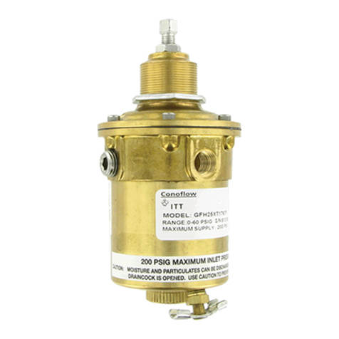
ITT Conoflow HP400 Instructions for use

HP400-IOM Rev. 0 7/20
THIS INFORMATION IS SUBJECT TO THE CONTROLS OF THE EXPORT ADMINISTRATION REGULATIONS (EAR). THIS INFORMATION SHALL NOT BE PROVIDED TO
NON-US PERSONS OR TRANSFERRED BY ANY MEANS TO ANY LOCATION OUTSIDE THE UNITED STATES CONTRARY TO THE REQUIREMENTS OF THE EAR.
105 Commerce Way
Westminster, SC 29693
Tel: (864) 647-9521
Fax: (864) 647-9568
INSTRUCTION AND MAINTENANCE MANUAL
HP400 HIGH PRESSURE REGULATOR
CAUTION: These instructions should be read and
understood prior to installation, use, or maintenance.
GENERAL PRODUCT OVERVIEW
The HP400 Regulator is a hand operated, self-contained,
spring loaded pressure reducing regulator. This unit offers the
safety and reliable service of a piston sensed regulator.
The model HP400 has non-venting piston sensor and a
captured bonnet feature. An adjustable stop to limit the
maximum output pressure is standard.
MATERIALS OF CONSTRUCTIONS
The HP400 will operate with any fluid (liquid or gas) compatible
with the materials of construction. To identify the materials of
construction refer to the Control Engineering Data contained
on page 3.
Body Brass
Bonnet Brass
Main Valve Seat Kel-F (Vespel Optional)
Sensor and Trim 300 Series Stainless Steel
Seals Teflon / Viton (Buna-N Optional)
REGULATOR CLEANING
The HP400 Series High Pressure Regulators are cleaned to
ITT Conoflow Specification ES8A 01 294.
OXYGEN SERVICE
Specification of materials in regulators used for oxygen service
is the USER’S RESPONSIBILITY. Cleaning for oxygen service
(per ES8A 01 297) to 3500 PSIG (24.20 MPa) is supplied by
ITT Conoflow at no additional cost. For special cleaning
requirements, the customer must supply specifications for the
desired level of cleaning. Cost will be advised prior to
performing the cleaning operation.
CAUTION: Maximum Supply Pressure 3500 PSI (24.20 MPa)
Maximum supply pressure can be derated based on
connection and internal material selections. See notes in CED
code (page 3).
An internal filter screen is provided in the inlet (“IN”) port only
to stop random contamination resulting from installation. An
auxiliary filter is recommended for all but the cleanest fluid.
Gaseous fluid must be free of excessive moisture to prevent
internal icing or condensation during operation.
OUTLET PRESSURE RANGES
OPTION CODE RANGE
“J” 20–2500 PSIG (0.14 -17.25 MPa)
PORTING CONFIGURATIONS
There are four (4) 1/4” NPTF connections on the HP400. The
supply connection port is labeled “IN” and the supply gauge
port is labeled “HI.” The outlet port is labeled “OUT” and the
outlet gauge port is labeled “LOW.” Care should be exercised
when installing the high pressure line to assure it is connected
to the inlet (“IN”) port, otherwise the regulator will not function
properly.
Teflon thread tape is the preferred thread sealant when the
regulator is installed.
INSTALLATION
The HP400 can be line or panel mounted. For line mounted
applications refer to porting configurations for proper
orientation of ports.
Panel Mounting:
1. Remove handwheel, knob, or “T” bar handle and insert the
regulator from the rear of the panel.
2. Projection of regulator through the panel may be controlled
by adjustment of panel mounting nuts
3. Replace the handwheel, knob, or “T” handle.
4. Connect inlet, outlet and gauge ports as applicable.
PRINCIPLE OF OPERATION
Turning the control knob clockwise will increase the force on
the range spring and, in turn, the outlet set pressure.
Conversely, turning the control knob counterclockwise will
decrease the force on the range spring and decrease the outlet
WARNING
Conoflow’s products are designed and
manufactured using materials and workmanship
required to meet all applicable standards. The use
of these products should be confined to services
specified and/or recommended in the Conoflow
catalogs, instructions, or by Conoflow application
engineers.
To avoid personal injury or equipment damage
resulting from misuse or misapplication of a
product, it is necessary to select the proper
materials of construction and pressure-
temperature ratings which are consistent with
performance requirements.

Page 2 of 6 HP400-IOM Rev. 0 7/20
THIS INFORMATION IS SUBJECT TO THE CONTROLS OF THE EXPORT ADMINISTRATION REGULATIONS (EAR). THIS INFORMATION SHALL NOT BE PROVIDED TO
NON-US PERSONS OR TRANSFERRED BY ANY MEANS TO ANY LOCATION OUTSIDE THE UNITED STATES CONTRARY TO THE REQUIREMENTS OF THE EAR.
set pressure. In equilibrium, the force exerted by the range
spring is balanced by the outlet pressure.
An unbalance between the outlet pressure and the set
pressure causes a corresponding reaction on the piston sensor
and valve. If the outlet pressure rises above the set pressure,
the piston sensor will lift allowing the valve to seat. If the outlet
pressure falls below the set pressure, the range spring will
push the piston down and unseat the valve. At equilibrium, the
valve plug assumes a position which supplies the required flow
while maintaining the outlet pressure at the set pressure.
(See Figure 1 on page 4 for labeled section view)
Setting Limit on Maximum Outlet (Control) Pressure
The handwheel on the HP400 Regulator can be adjusted to
limit the maximum outlet pressure attainable to any value up to
100% of the rated outlet pressure range. To set this limit,
connect the regulator to a pressure source and a gauge to
indicate the regulator outlet pressure. Apply an inlet pressure
to the regulator equal to the maximum inlet pressure expected
in service. Remove the hole plug from the handwheel and
loosen the jam nut using a 9/16” socket. Using a screwdriver,
turn the adjusting screw clockwise until the indicated outlet
pressure is at the pressure at which the limit is desired. Spin
the handwheel clockwise until it stops against the top of the
bonnet. Then turn the handwheel back about 1/8 of a turn
counterclockwise and hold it in this position. While doing so,
tighten the jam nut against the handwheel with 70 – 120 in.lbs
of torque. Turn the handwheel counterclockwise until it is no
longer seated against the top of the bonnet. Check by
adjusting the handwheel clockwise to insure that it stops
against the bonnet when the output pressure reaches the
desired maximum pressure.
SCHEDULED MAINTENANCE
All regulators require scheduled maintenance to remove
deposits left by the media and to replace parts worn or
damaged as a result of use. Annual maintenance is
recommended when the regulator is used under normal
conditions. More frequent maintenance may be required due to
the condition, cleanliness and/or corrosiveness of the media.
TOOLS REQUIRED
7/16” Wide blade screwdriver bit having 1/8” wide x 3/8” deep
notch (seat gland)
9/16” Socket (jam nut within standard hand knob)
9/16” Open end wrench (jam nut on wrench knob or “T”
handle)
1-7/8” Socket or wrench (bonnet)
Internal snap ring pliers (retaining rind in sensor bore)
Pliers (to remove sensor from bore)
Other tools and maintenance aids include a vise, tweezers,
clean lint free cloth, swabs, and a torque wrench.
CAUTION: MAINTENANCE
It is recommended that maintenance be performed by a person
experienced in the operation and repair of high pressure
regulators.
Maintenance of this unit is best performed by gripping a
protruding end of a pipe fitting installed into the regulator body.
WARNING: Bleed System Pressure Prior to Removing
Regulator for Servicing.
MAINTENANCE PROCEDURE
1. Adjust the handwheel to the full counterclockwise position
until the handwheel, hole plug, jam nut, and adjusting screw
are fully disengaged.
2. Using a 1-7/8” wrench, loosen and remove the bonnet.
3. Remove the spring button, range spring, and the range
spring backup plate.
4. With internal snap ring pliers, remove the retaining ring.
5. Using pliers, grip and remove the piston sensor for service
to the backup ring and O-ring.
6. The main valve assembly can be disassembled by using a
modified screwdriver bit to turn the seat gland
counterclockwise until it is free from the regulator body. The
main valve plug, main valve sear, and the plug spring can be
lifted from the body.
7. Remove the main valve seat from the seat gland.
(See Figure 2 on page 4 for exploded view)
THE REGULATOR IS RE-ASSEMBLED IN THE
REVERSE ORDER OF DISASSEMBLY, OBERSVING
THE FOLLOWING PRECAUTIONS:
1. Inspect all component parts and replace those worn or
damaged with ITT Conoflow replacement parts.
2. All component parts should be cleaned to the cleanliness
level required for safe operation with the media used. All parts
in the flow stream must be free of particles which could prevent
proper seating of the main valve.
3. Place the plug spring in the body bore (See Figure 3 for
section view) Place the main valve plug into the body.
Lubricate the threads of the seat gland with Krytox grease and
press the main valve seat into the seat gland. For the standard
Kel-F (PCTFE) seat, install the seat into the seat gland with the
identification face groove facing out of the seat gland (ignore
this orientation requirement if the valve seat is Vespel).
4. Carefully guide the seat gland and the main valve seat
assembly into the body, as to not scratch or score the piston
sensor bore. Once in place screw the seat gland into the body.
Make sure the seat is correctly positioned in the seat gland
before tightening the seat gland.
5. Lubricate the O-ring(s) and the backup ring with Krytox.
Lubricate the groove on the piston sensor with Krytox. Install
the O-ring in the groove. Install the backup ring in the groove
on the side which is closest to the small diameter end of the
sensor. If the standard scarf cut Teflon backup ring is used, be
careful not to bend the backup ring too much. If an optional
Buna-N backup ring is used, install the backup ring with the
curved side towards the O-ring.
6. Lightly lubricate the piston sensor bore of the body with
Krytox and slide the piston sensor into the body with the small

Page 3 of 6 HP400-IOM Rev. 0 7/20
THIS INFORMATION IS SUBJECT TO THE CONTROLS OF THE EXPORT ADMINISTRATION REGULATIONS (EAR). THIS INFORMATION SHALL NOT BE PROVIDED TO
NON-US PERSONS OR TRANSFERRED BY ANY MEANS TO ANY LOCATION OUTSIDE THE UNITED STATES CONTRARY TO THE REQUIREMENTS OF THE EAR.
diameter facing out of the bore. Move the piston sensor in the
bore and make sure the piston sensor is free to move with only
light resistance and the main valve plug and the plug spring will
push the piston sensor back up.
7. Install the retaining ring in the groove in the piston sensor
bore using internal snap ring pliers.
8 Place the range spring backup plate, the range spring, and
the spring button on the piston sensor. Lubricate the center of
the spring button and the large internal threads and chamfer of
the bonnet with Krytox.
9. Screw the bonnet onto the body and tighten it to 50 ft.lbs.
10. Lubricate and install the handwheel assembly onto the
bonnet. The handwheel assembly consists of the handwheel,
the hole plug, the adjusting screw, and the jam nut.
11. Install a filter screen in the inlet port of the body.
Prior to re-installation, the regulator should be connected to a
pressure source with a media compatible with use of the
regulator and pressurized to check for internal and external
leakage and operating characteristics.
Regulator Model Breakdown (CED Code)
Control Engineering Data is intended to provide a single source from which one can determine, in detail, the full scope of the
product line. In addition to the materials of construction, diaphragm and elastomer selection, it also provides all necessary
data regarding adjustment option and range selections. Control Engineering Data also provides a means of communicating
by way of a code number which is fully descriptive in product selection. All catalog numbers received must contain fifteen
(15) characters.
1 through 5 HP400 Pressure Reducing Regulator, Piston Type (Low Flow)
Body / Bonnet / Trim
6 B Brass / Brass / 300 Stainless Steel
Main Valve Seat(s) / Backup Rings / O-Ring(s)
7 through 8 11 Kel-F / Teflon / Buna-N
12 Vespel / Teflon / Buna-N (See Note 1)
13 Kel-F / Buna-N / Buna-N
14 Vespel / Buna-N / Buna-N (See Note 1)
17 Vespel / Teflon / Viton (See Note 1)
18 Kel-F / Teflon / Viton (Standard)
9 R Non-Relieving, Captured Bonnet
10 through 11 81 1/4” NPT Connections (See Note 2)
12 P Panel Mounting (2-nut) (Optional)
S Plain bonnet (No threads) (Standard)
13 A Regulator is cleaned to ITT Conoflow Specification ES8A 01 294
B Oxygen Cleaning: Specification of materials in regulators used for oxygen service
is the user’s responsibility. Cleaning for oxygen service to 3500 PSIG
(24.20 MPa) is supplied by ITT Conoflow at no additional cost.
C Customer Specified Cleaning: Customer to specify the desired level of
cleanliness. ITT Conoflow will advise cost prior to performing cleaning operation.
Specification of materials is the USER’S RESPONSIBILITY.
14 B Handwheel (Large)
K Wrench knob with locking device (Optional)
T “T” bar handle (Optional)
15 J 20-2500 PSI (0.14-17.25 MPa)
NOTES:
1. The use of the Vespel valve seat increases the inlet pressure rating to 6000 psig
2. Gauge port connections are 1/4” NPT.

Page 4 of 6 HP400-IOM Rev. 0 7/20
THIS INFORMATION IS SUBJECT TO THE CONTROLS OF THE EXPORT ADMINISTRATION REGULATIONS (EAR). THIS INFORMATION SHALL NOT BE PROVIDED TO
NON-US PERSONS OR TRANSFERRED BY ANY MEANS TO ANY LOCATION OUTSIDE THE UNITED STATES CONTRARY TO THE REQUIREMENTS OF THE EAR.
CONNECTION IDENTIFICATION AND TYPICAL GEOMETRY
FIGURE 1: HP400 REGULATOR SECTIONED VIEW
FIGURE 2: HP400 REGULATOR EXPLODED VIEW

Page 5 of 6
HP400-IOM Rev. 0 7/20
THIS INFORMATION IS SUBJECT TO THE CONTROLS OF THE EXPORT ADMINISTRATION REGULATIONS (EAR). THIS INFORMATION SHALL NOT BE PROVIDED TO
NON-US PERSONS OR TRANSFERRED BY ANY MEANS TO ANY LOCATION OUTSIDE THE UNITED STATES CONTRARY TO THE REQUIREMENTS OF THE EAR.
FIGURE 3: STANDARD HANDKNOB DIMENSIONAL DRAWING
FIGURE 4: OPTIONAL WRENCHKNOB DIMENSIONAL DRAWING
FIGURE 5: OPTIONAL “T” BAR HANDLE DIMENSIONAL DRAWING

Page 6 of 6 HP400-IOM Rev. 0 7/20
THIS INFORMATION IS SUBJECT TO THE CONTROLS OF THE EXPORT ADMINISTRATION REGULATIONS (EAR). THIS INFORMATION SHALL NOT BE PROVIDED TO
NON-US PERSONS OR TRANSFERRED BY ANY MEANS TO ANY LOCATION OUTSIDE THE UNITED STATES CONTRARY TO THE REQUIREMENTS OF THE EAR.
TROUBLESHOOTING
When performing necessary corrective action in the following operations, refer to the MAINTENANCE section for the necessary
procedure.
PROBLEM:
The regulated pressure continues to increase after lock-up and without change in the control mechanism position.
POSSIBLE CAUSE:
The main valve seat needs replacement; follow maintenance procedure and regulator assembly.
PROBLEM:
Continuous leakage through the bonnet with the outlet pressure on the regulator.
POSSIBLE CAUSE:
Sensor O-ring is worn, leaking, and needs to be replaced.
PROBLEM:
Regulated pressure drops off sharply when the flow is within the regulator’s capabilities.
POSSIBLE CAUSE:
Clogged inlet screen. Remove the old filter with a sharp instrument and press in a new filter using the blunt end of an instrument.
PROBLEM:
Outlet Pressure will not adjust high enough.
POSSIBLE CAUSE:
Supply pressure is too low and needs to be increased.
Maximum pressure limit (handwheel) is improperly adjusted and needs to be re-adjusted, follow maintenance procedure “setting the
maximum output limit.”
An ITT Company
Table of contents
Other ITT Controllers manuals

ITT
ITT Bell & Gossett ZoneTrol II Z-2 Manual

ITT
ITT Engineered Valves Advantage 2.1 8 Series User manual

ITT
ITT McDonnell & Miller PS-802 Series Installation and operating instructions

ITT
ITT Advantage Actuator 2.0 User manual

ITT
ITT Hydrovar Installation and operating instructions

ITT
ITT Lowara GENYO 16A / R15-25 User manual

ITT
ITT Engineered Valves Advantage 2.1 User manual

ITT
ITT Conoflow GB 2800 Instructions for use

ITT
ITT Bell & Gossett ZoneTrol II Z-1 Manual

ITT
ITT GFH20XT1767C Instructions for use