Diagraph - an ITW Company PA/4600 & PA/6000 User Manual
System Modules Page 7
System Modules
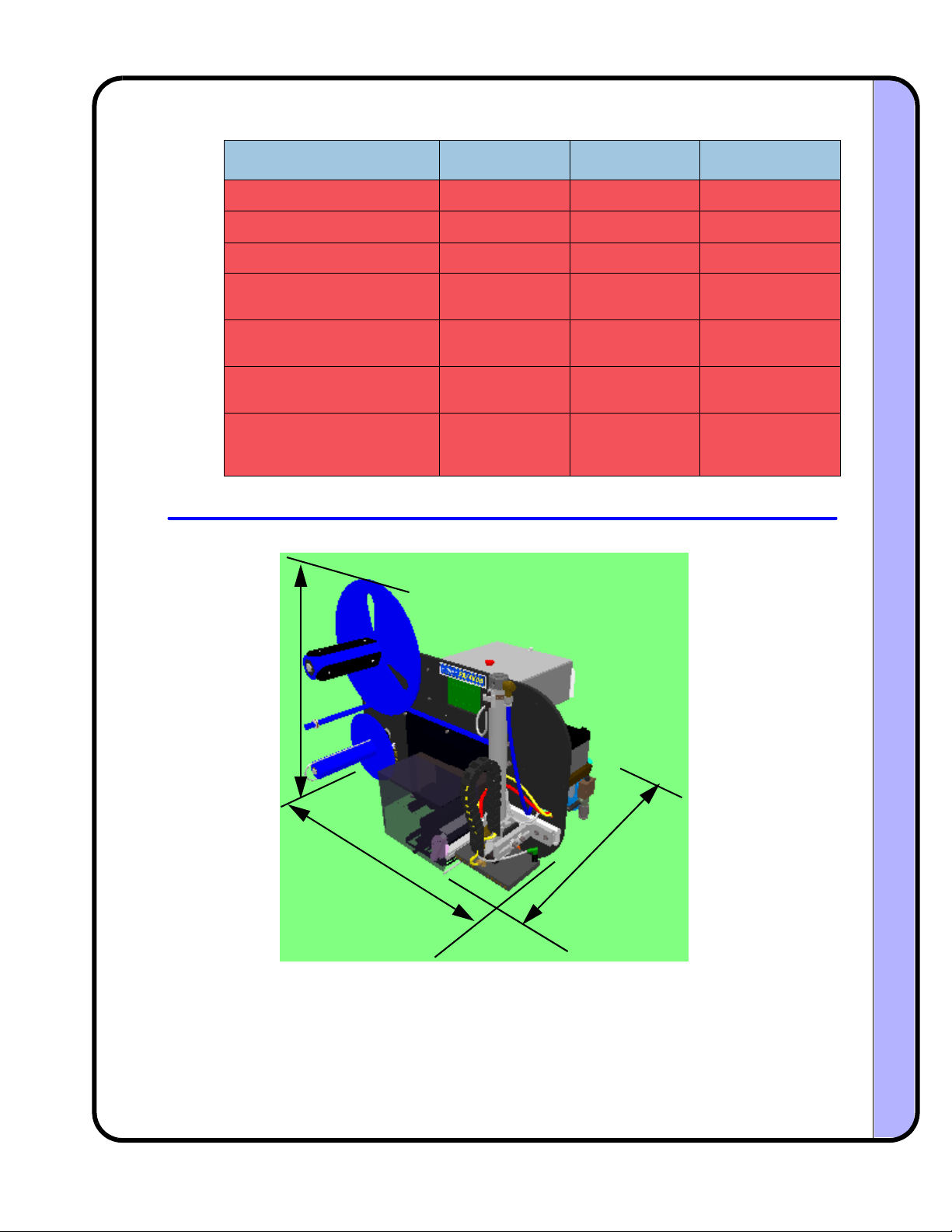
Stand P/N: 6160-329
2.2 Pneumatics SubSystem
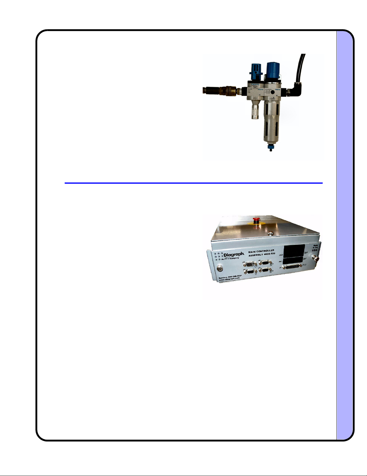
PAM (Pneumatic Air Manifold) P/N: 4600-701
Tamp Cylinder P/N: 4600-743 (10 inch), 4600-745 (20 inch)
ThestandholdstheyokeassemblyofthePA/
4600orPA/6000,andallowsthesystemtobe
orientatedinavarietyofpositionstosuit
applicationrequirements.Thestandemploys
ahandcranktosetverticalposition,anda
seriesofmountingpointsforitemssuchas:
warningtower,remoteuserinterface,and
inletfilter/regulator.Thestandcontainsthree
lockablecastersthatpreventrolling
movement,aswellasrotationalmovement.
Thecolumnofthestandisdesignedtobe
rotated,whichcanhelpinstallationswhere
thefrontlegofthet‐baseinterfereswith
existingequipment.
Theairmanifoldcontrolstheoperationof
thetampcylinderandthedeliveryofthe
labelfromtheprintertotheproduct.The
manifoldhastwopressureregulators,onefor
tamppressureandtheothercontrolsboth
vacuumandblow.Twoflowcontrolslimit
thevolumeofairgoingtotheairassistand
blowvalves.Therearetwopressuregauges
thatmonitorthepressuresetbythe
regulators.Apressuresensormonitorsthe
incomingairlevelanddisplaysitonadigital
readoutandbargraph.Anerroristriggeredif
theincomingpressuredropsbelowtheset
pointvalue.
Thetampcylinderemploysadual‐rod
designtoachieveveryhighspeedextension
andretraction,withoutrotation.Thetamp
cylinderextensionandretractionspeedis
controlledbymeansofthetamppressure
settingontheairmanifoldandtheflow
controlsonthecylinderbody.Anadjustable
aircushiononthetopofthecylinder
dampensthereturnenergy.Amagneticreed
switch,attachedtothetopofthecylinder,
detectstheimmediatereturnofthecylinder
toitshomeposition.