ITW Trans Tech Aero 60 User manual

INDEX
Release 2.0 PAGE 1
AERO 60/90
Release 2.0
REV 1 - #000 – 0000
Operator’s
Manual
Trusted Partner for Your Product Decorating Needs
Trans Tech 475 North Gary Avenue, Carol Stream, IL 60188
Tel +1 (630) 752 4000 Fax +1 (630) 752 4467
Email [email protected]
www.itwtranstech.com www.itwids.com
A MEMBER OF

Aero 60/90 INDEX
Release 2.0 PAGE 2
THIS PAGE LEFT BLANK

Aero 60/90 INDEX
Release 2.0 PAGE 3
Contents
AERO 60/90 .....................................................................................................................1
1.1. Safety......................................................................................................................... 5
1.1.1 Symbols and their Interpretations......................................................................... 5
1.1.2 Liability .................................................................................................................5
1.1.3 Warnings and Cautions........................................................................................6
1.1.4 Application Restrictions........................................................................................6
1.2. Installation Instructions.............................................................................................. 7
1.2.1 Selecting the location........................................................................................... 7
1.2.2 Connection to power ............................................................................................ 7
1.2.3 Connecting to Air Supply...................................................................................... 7
1.2.4 Setting Pressure Regulator.................................................................................. 8
1.2.5 Flow Controls .......................................................................................................8
1.2.6 Mounting the Machine..........................................................................................9
1.3. Printer Operation ..................................................................................................... 10
1.3.1 Description of Ink Cup Tooling........................................................................... 10
1.3.2 Installation of the Cliché and Ink Cup.................................................................11
1.3.3 Removal of the Cliché and Ink Cup.................................................................... 12
1.3.4 Handling of the Ink Cup...................................................................................... 13
1.4. Operating Controls................................................................................................... 14
1.4.1 Description of the Operating Panel ....................................................................14
1.4.2 The Operating Control Functions....................................................................... 15
1.4.3 Screen Map........................................................................................................16

Aero 60/90 INDEX
Release 2.0 PAGE 4
1.5. Setup ....................................................................................................................... 17
1.5.1 Boot Up Screen..................................................................................................17
1.5.2 Screen Info.........................................................................................................17
1.5.3 Main Screen after MAIN button pressed ............................................................18
1.5.4 Second Screen................................................................................................... 19
1.5.5 PRD Data........................................................................................................... 20
1.5.6 PRD Data Reset................................................................................................. 20
1.5.7 Pad Delay........................................................................................................... 21
1.5.8 Cycle Delay........................................................................................................ 21
1.5.9 Third Screen.......................................................................................................22
1.5.10 Manual Setup................................................................................................... 23
1.5.11 I/OStatus ..........................................................................................................24
1.5.12 Setup Screen....................................................................................................25
1.5.13 Batch Counter ..................................................................................................25
1.5.14 Increase number of prints.................................................................................26
1.5.15 Alarms .............................................................................................................. 26
1.5.16 Standard Errors................................................................................................27
1.6. Electrical Schematics............................................................................................... 28
1.6.1 Version 16 Bit PLC.............................................................................................28
1.6.2 Version 32 Bit PLC.............................................................................................34
1.7. Pneumatic Schematics............................................................................................ 42
Aero 60/90 Safety 1.1
Release 2.0 PAGE 5
1.1. Safety
1.1.1. Symbols and their Interpretations
WARNING Neglecting a safety instruction identified with the WARNING symbol may
lead to personal injury.
CAUTION Neglecting a safety instruction identified with the CAUTION symbol may
lead to property damage.
POINTER It is strongly recommended to observe instructions identified with a
POINTER symbol.
1.1.2. Liability
In no event will ITW TRANS TECH be responsible or liable for indirect or
consequential damages resulting from the use of this equipment.
The information contained in this manual is subject to change due to
improvements in design.
Though this document has been checked for inaccuracies, ITW TRANS
TECH does not assume responsibility for any errors contained herein.
This manual is provided as an aid when operating the Aero 60/90 pad
printing machine. Prior to operation, it is strongly advised that the user be
thoroughly familiar with the Aero 60/90 operating manual.
ITW TRANS TECH is not responsible or liable for any disadvantage
occurred for not following the operating instructions.
All operators must be sufficiently trained.

Aero 60/90 Safety 1.1
Release 2.0 PAGE 6
1.1.3. Warnings and Cautions
Switch off main switch prior to connecting/disconnecting power.
Disconnect power prior to opening the electrical enclosure.
Switch the MAIN DISCONNECT off and disconnect the power cord prior to working
on the electrical system.
1.1.4. Application Restrictions
Any use other than described in this manual may cause damage to the
equipment, personal injury or property damage.
Aero 60/90 Installation
Instructions 1.2
Release 2.0 PAGE 7
1.2. Installation Instructions
1.2.1. Selecting the location
Choose a well ventilated area away from direct sunlight to install your pad printing
machine. The ideal conditions for the inks used in pad printing are approximately
20° C (68° F) and 40 - 60 % humidity.
Make sure the machine is positioned away from walls and other obstructions and
placed on a flat surface. The guards, operating panel and other machine openings
must be accessible. Ensure adequate area for setup tooling and for storage of parts
before and after printing.
Temperature Humidity
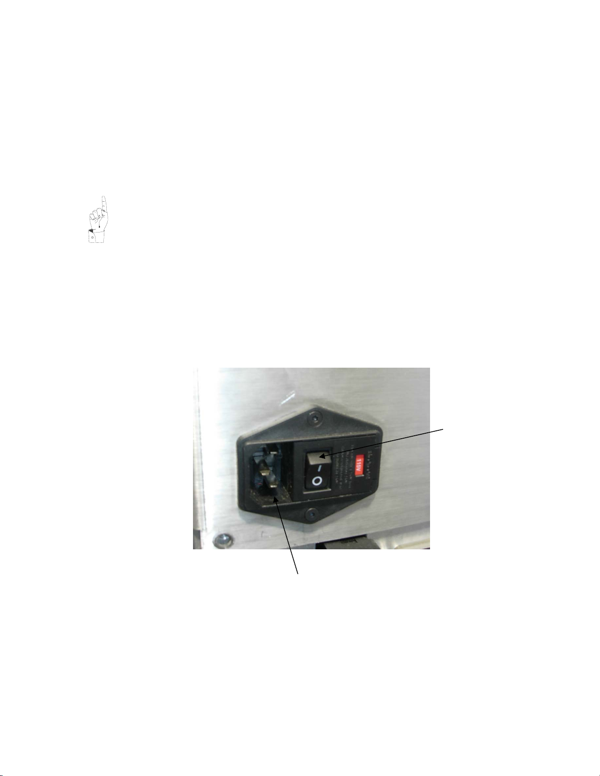
1.2.2. Connection to power
POWER CORD RECEPTACLE
MAIN DISCONNECT

Aero 60/90 Installation
Instructions 1.2
Release 2.0 PAGE 8
1.2.3 Connecting to Air Supply
The machine requires clean, dry air. Minimum requirement:
- 6 bar (85 psi)
- 5 cfm
Air connection is to quick disconnect adapter (included) or to ¼ NPT female thread.
1.2.4 Setting Pressure Regulator
Adjust system pressure to 6 bar (85 psi) by lifting the adjusting knob to unlock, then turning the knob
clockwise to increase the pressure or counterclockwise to decrease the pressure. Push down on the
adjusting knob to lock the regulator after making adjustments.
1.2.5
Flow Controls
The Flow Controls are used to adjust the speed of the pad movement.
I/O connections
Flow forward
Flow backward
Flow up
Flow down
Aero 60/90 Installation
Instructions 1.2
Release 2.0 PAGE 9
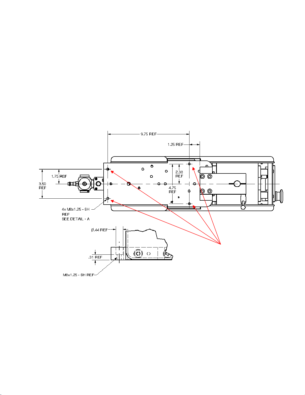
1.2.6 Mounting the Machine
Using the holes marked “A” in the following drawing, Install four (4) M6 x 20 S.H.C.S and tighten to 7
ft-lbs of torque. If preferred the machine can also be mounted form beneath using (4) M8-1.25 metric
fasteners. Torque M8-1.25 fasteners to 17 ft-lbs.
“A”

Printer Operation
Aero 60/90
1.3
Release 2.0 Page 10
1.3. Printer Operation
1.3.1. Description of Ink Cup Tooling
1
5
3
2
4
Illustration 2-1. Cliché assembly device
Bill of Materials for Ink Cup Assembly
No.
Description
Part number Aero 90
Part number Aero 60
1
Setup Table
9901-30-001
9901-31-001
2
ExpressLiner
9260-20-004 (std)
9260-20-005 (tall)
9260-10-004
3
SpaceFrame
9260-26-100
9260-16-100
4
Magnetic Cup Clamp
9901-30-002
9901-31-002
5
Cliché
Contact Trans Tech
Contact Trans Tech
This manual suits for next models
1
Table of contents
Other ITW Printer manuals


