ITW FOXJET Solo 45 Series User manual

1 Missouri Research Park Drive • St. Charles, MO 63304 • 1-800-369-5384
Illinois Tool Works Inc © 2013
Thermal Jet
Ink Jet System
5780-329
Revision M
Operations
Manual

Thermal Jet
Ink Jet System
Operations Manual
5780-329
Revision M
The information contained in this manual
is correct and accurate at the time of its
publication. Foxjet reserves the right to
change or alter any information or
technical specifications at any time and
without notice.
©2013 Illinois Tool Works Inc.
All rights reserved
Printed in the United States of America
Ink Cartridge: The SoloSeries has been engineered
and designed to work with Foxjet ink cartridges. The
SoloSeries’ Smart Level Ink Detection System,
which provides ink level monitoring to ensure com-
plete ink usage and product safety, will not be func-
tional if used with non-Foxjet ink cartridges.

The SoloSeries Thermal Jet system, including all components unless otherwise
specified, carries a limited warranty.
The inks and conditioners used with the SoloSeries Thermal Jet system carry a limited
warranty.
For all warranty terms and conditions, contact Foxjet an ITW Company for a complete
copy of the Limited Warranty Statement.
Warranty:
Thermal Jet

Thermal Jet
Thermal Jet Operations Manual Rev M
Section 1: Safety and Ink Cartridge Usage . . . . . . . . . . . . . . . . . . . . . . . . . . . . . . . . . . . . . . . . 1
Section 2: Quick Start .. . . . . . . . . . . . . . . . . . . . . . . . . . . . . . . . . . . . . . . . . . . . . . . . . . . . . . . . . 2
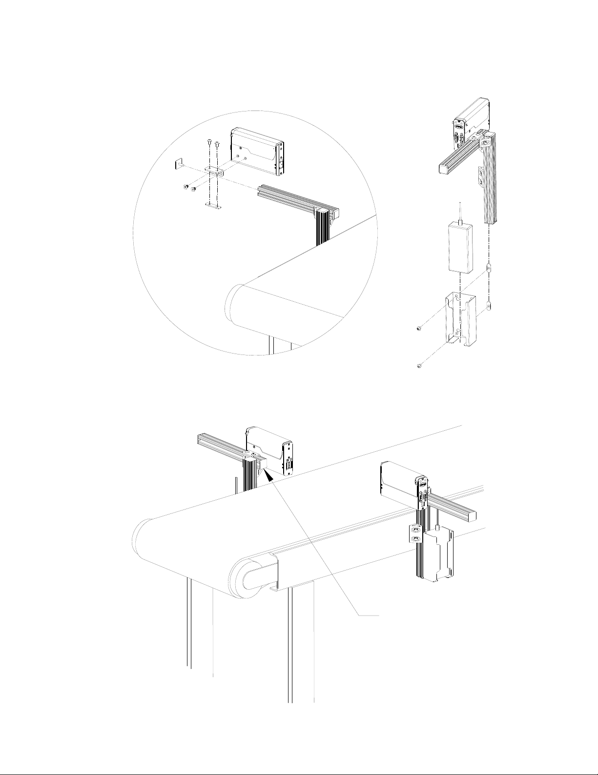
Step 1: Assemble Bracketry . . . . . . . . . . . . . . . . . . . . . . . . . . . . . . . . . . . . . . . . . . . . . . . . 3
Step 2: Assemble Bracketry to Conveyor .. . . . . . . . . . . . . . . . . . . . . . . . . . . . . . . . . . . . . 3
Step 3: Assemble Print Head and Power Supply to Bracketry . . . . . . . . . . . . . . . . . . . . . . 4
Step 4: Adjust Print Head to Substrate . . . . . . . . . . . . . . . . . . . . . . . . . . . . . . . . . . . . . . . . 5
Step 5: Insert Cartridge Pen into Print Head .. . . . . . . . . . . . . . . . . . . . . . . . . . . . . . . . . . . 6
Step 6: Cabling, Power, and Serial Port Setup . . . . . . . . . . . . . . . . . . . . . . . . . . . . . . . . . . 7
Step 7: Configure the Print Head . . . . . . . . . . . . . . . . . . . . . . . . . . . . . . . . . . . . . . . . . . . 10
Step 8: Create a Message . . . . . . . . . . . . . . . . . . . . . . . . . . . . . . . . . . . . . . . . . . . . . . . . . 11
Step 9: Print a Message .. . . . . . . . . . . . . . . . . . . . . . . . . . . . . . . . . . . . . . . . . . . . . . . . . . 12
Section 3: Hand Held Controller or GUI Functionality . . . . . . . . . . . . . . . . . . . . . . . . . . . . . 13
Home Screen .. . . . . . . . . . . . . . . . . . . . . . . . . . . . . . . . . . . . . . . . . . . . . . . . . . . . . . . . . . 14
Main Menu . . . . . . . . . . . . . . . . . . . . . . . . . . . . . . . . . . . . . . . . . . . . . . . . . . . . . . . . . . . . 16
Message Editor continued: User Defined Time Codes .. . . . . . . . . . . . . . . . . . . . . . . . . . 18
Status Screen .. . . . . . . . . . . . . . . . . . . . . . . . . . . . . . . . . . . . . . . . . . . . . . . . . . . . . . . . . . 25
Section 4: Maintenance & Shutdowns . . . . . . . . . . . . . . . . . . . . . . . . . . . . . . . . . . . . . . . . . . . 26
Daily Maintenance, Ink Cartridge . . . . . . . . . . . . . . . . . . . . . . . . . . . . . . . . . . . . . . . . . . 26
Weekly to Monthly Maintenance, Print Head . . . . . . . . . . . . . . . . . . . . . . . . . . . . . . . . . 27
Shutdowns Less Than 3 Days .. . . . . . . . . . . . . . . . . . . . . . . . . . . . . . . . . . . . . . . . . . . . . 27
Shutdowns More Than 3 Days . . . . . . . . . . . . . . . . . . . . . . . . . . . . . . . . . . . . . . . . . . . . . 27
Section 5: Troubleshooting . . . . . . . . . . . . . . . . . . . . . . . . . . . . . . . . . . . . . . . . . . . . . . . . . . . . 28
Appendix A: Specifications . . . . . . . . . . . . . . . . . . . . . . . . . . . . . . . . . . . . . . . . . . . . . . . . . . . . 29
Appendix B: Theory of Operation . . . . . . . . . . . . . . . . . . . . . . . . . . . . . . . . . . . . . . . . . . . . . . 33
Thermal Jet Print Heads . . . . . . . . . . . . . . . . . . . . . . . . . . . . . . . . . . . . . . . . . . . . . . . . . . 33
Handheld Controller . . . . . . . . . . . . . . . . . . . . . . . . . . . . . . . . . . . . . . . . . . . . . . . . . . . . . 34
Interconnect Diagram . . . . . . . . . . . . . . . . . . . . . . . . . . . . . . . . . . . . . . . . . . . . . . . . . . . . 36
Appendix C: File Backup and Restore . . . . . . . . . . . . . . . . . . . . . . . . . . . . . . . . . . . . . . . . . . . 37
File Backup . . . . . . . . . . . . . . . . . . . . . . . . . . . . . . . . . . . . . . . . . . . . . . . . . . . . . . . . . . . . 38
Restoring Backed-Up Files .. . . . . . . . . . . . . . . . . . . . . . . . . . . . . . . . . . . . . . . . . . . . . . . 39
Appendix D: Configuring a PC to Communicate with the Handheld . . . . . . . . . . . . . . . . . . 40
Windows XP® . . . . . . . . . . . . . . . . . . . . . . . . . . . . . . . . . . . . . . . . . . . . . . . . . . . . . . . . . 40
Windows 2000® . . . . . . . . . . . . . . . . . . . . . . . . . . . . . . . . . . . . . . . . . . . . . . . . . . . . . . . . 42
Appendix E: Font Samples .. . . . . . . . . . . . . . . . . . . . . . . . . . . . . . . . . . . . . . . . . . . . . . . . . . . . 44
Appendix F: Creating Logo Files . . . . . . . . . . . . . . . . . . . . . . . . . . . . . . . . . . . . . . . . . . . . . . . 45

Thermal Jet
Thermal Jet Operations Manual Rev M
Appendix G: Uploading Files to the Print Head and File Management . . . . . . . . . . . . . . . . 47
Appendix H: Communicating Directly to the Print Head . . . . . . . . . . . . . . . . . . . . . . . . . . . 52
Appendix I: Aligning the 1" (25.4 mm) Print Head . . . . . . . . . . . . . . . . . . . . . . . . . . . . . . . . 53
Appendix J: Bulk Ink Supply . . . . . . . . . . . . . . . . . . . . . . . . . . . . . . . . . . . . . . . . . . . . . . . . . . 54
Appendix K: Part Numbers - Consumables and Service Parts . . . . . . . . . . . . . . . . . . . . . . . 60
Consumables .. . . . . . . . . . . . . . . . . . . . . . . . . . . . . . . . . . . . . . . . . . . . . . . . . . . . . . . . . . 60
Service Parts . . . . . . . . . . . . . . . . . . . . . . . . . . . . . . . . . . . . . . . . . . . . . . . . . . . . . . . . . . . 60
Optional Equipment . . . . . . . . . . . . . . . . . . . . . . . . . . . . . . . . . . . . . . . . . . . . . . . . . . . . . 63

Thermal Jet Section 1: Safety and Ink Cartridge Usage
Thermal Jet Operations Manual Rev M Page 1
Section 1: Safety and Ink Cartridge Usage
Following is a list of safety symbols and their meanings, which are found throughout this
manual. Pay attention to these symbols where they appear in the manual.
Wear safety goggles when performing the procedure described!
Caution or Warning! Denotes possible personal injury and/or damage to the equipment.
Caution or Warning! Denotes possible personal injury and/or equipment damage due to
electrical hazard.
NOTE: (Will be followed by a brief comment or explanation.)
ESD protection should be worn when servicing internal printed circuit boards.
After service to the equipment is completed, replace all protective devices such as ground-
ing cables and covers before operating the equipment.
It is extremely important to:
• Clean up all spills with the appropriate solvents immediately and dispose of all waste according
to local and state regulations.
• Wear safety glasses and protective clothing, including gloves, when handling all inks and condi-
tioners.
• Store inks and solvents under the recommended conditions found on the MSDS (Material
Safety Data Sheet).
!
!

Thermal Jet Section 2: Quick Start
Thermal Jet Operations Manual Rev M Page 2
Section 2: Quick Start
Contents:
•PrintHead
• Bracketry Kit
• Power Supply, 15 V
• Power Supply Bracket
•PowerCord
• Software
TYPICAL INSTALLATION
CONTROLLER
OPTIONAL HAND HELD
TYPICAL INSTALLATION

Thermal Jet Section 2: Quick Start
Thermal Jet Operations Manual Rev M Page 3
Step 1: Assemble Bracketry
Step 2: Assemble Bracketry to Conveyor

Thermal Jet Section 2: Quick Start
Thermal Jet Operations Manual Rev M Page 4
Step 3: Assemble Print Head and Power Supply to Bracketry
Ensure bar is
behind front
face of print head

Thermal Jet Section 2: Quick Start
Thermal Jet Operations Manual Rev M Page 5
Step 4: Adjust Print Head to Substrate
ADJUST THE PRINT
HEAD TO THE
SUBSTRATE WITH
THIS BRACKET
.1" (2.5mm) GAP
RECOMMENDED
Adjust print head vertically to meet requirement.
Adjust print head horizontally to set print gap.

Thermal Jet Section 2: Quick Start
Thermal Jet Operations Manual Rev M Page 6
Step 5: Insert Cartridge Pen into Print Head
Rotate Cover
Open
Rotate Pen Cartridge
down until it snaps in
place.
NOTE: The pen is
released by pressing
down on the Finger
Release Tab and pull-
ing up on the rear of
the cartridge.
Close Cover
PEN STOP
When inserting cartridge, aim nose at an
angle towards black pogo pin component.
Slide pen cartridge up to Pen Stop.
Insert Pen Cartridge at an angle up to
Pen Stop
PEN STOP
After pen cartridge
is installed
FINGER RELEASE TAB
FINGER RELEASE TABS

Thermal Jet Section 2: Quick Start
Thermal Jet Operations Manual Rev M Page 7
Step 6: Cabling, Power, and Serial Port Setup
Cabling
CAUTION: Power should be disconnected from the print head prior to connecting or dis-
connecting any external device, including: PC, controller, or print head daisy chain cables.
Electrical arcing may occur if external cabling is connected or disconnected while power is
supplied to the unit.
Print heads are controlled via a COM port from a PC or an Hand held controller. One com
port can control up to eight 1/2" print heads, four 1" print heads, or any combination of the
two totalling eight print cartridges. Using the supplied serial cables, connect the print heads
daisy chain style by connecting the output port of one print head to the input port of the
next. Then connect the COM port of the PC or Hand Held Controller to the daisy chain. A
PC connects to the input port of the first head in the daisy chain, while an Hand Held Con-
troller connects to the output port of the last.
PRINT HEAD
HAND HELD CONTROLLER
HH Controller Cable
5780-616-06
DB9 F-F
COM PORT
PC OR LAPTOP
Print Head Cable
5780-319-06
DB9 M-F

Thermal Jet
Thermal Jet Operations Manual Rev M Page 8
Power
CAUTION: Power should be disconnected from the print head prior to connecting or dis-
connecting any external device, including: PC, controller, or print head daisy chain cables.
Electrical arcing may occur if external cabling is connected or disconnected while power is
supplied to the unit.
Install the power plug from the previously mounted
power supply into the power jack on the rear of
each print head.
Press and hold the "PURGE" button on the rear of
the print head while slowly moving a piece of
paper, cardboard, or comparable material in front
of the Print cartridge. Print several purge images
and validate that all channels are printing. If not,
refer to “Section 4: Maintenance & Shutdowns” on
page 26.
The power supply for the controller or the com-
puter may now be installed.
Serial Port Setup
NOTE: Depending on GUI / Controller status, this step may already be complete.
If a computer will be used, install the PC software
included with the print head. Follow the installation
prompts, and at this prompt, select "Interface 1
Serial Print Head".
After the GUI program has been installed, launch
the program.
Ensure the home screen menu is present via the Hide Menu / Show Menu button, and
then press the Control Panels button.
NOTE: Do not rub the print cartridge face with
the print sample material as this will scratch
the orifice array and affect print quality.

Thermal Jet
Thermal Jet Operations Manual Rev M Page 9
To ensure the baud rate is set for 57600, press the button beneath the Port/Baud column
and adjust if necessary. Press the OK button to exit the Serial Port Setup screen.
If "Serial Print Head: Task x" is not shown on theCOM1 Function button, press the button
and select the Serial Print Head option. Press the OK button to exit the COM 1 Function
screen. Press OK again to exit the System Setup screen.
Press the System Setup button, and then the Serial Ports tab.

Thermal Jet
Thermal Jet Operations Manual Rev M Page 10
Step 7: Configure the Print Head
Set the number of print heads, identify their positions relative to the controller, and select
the appropriate print head type by touching each one and then the drop down box.
Print head setup complete. Next, select the Encoder tab, and choose the desired encoder
type.
Auto Speed Detect:
Line speed
automatically
detected via print
head photo cells.
External Encoder:
Line speed measured by
an externally mounted
encoder and connected
to the last print head in
the daisy chain
Touch this
box, then type
in the desired
speed
On the home screen, press the Control Panels button, and then press the System Setup
button. On the Print Heads page press the Redo Print Head Setup button. Select the
desired direction.
Fixed Speed:
User types in the
desired line speed

Thermal Jet
Thermal Jet Operations Manual Rev M Page 11
Step 8: Create a Message
File Menu
Variable Field
Product Setup Product Side
Zoom
Field
Coordinates
Field
Selection
Font
Selection
Count Code
Date Code
Time Code
Alpha / Numeric
Quick Save
Create and save the message, and then exit the message editor.
Message
Display
Area
From the home screen, select the Messages button and then the New button to enter the
message editor.
Logo Barcode

Thermal Jet
Thermal Jet Operations Manual Rev M Page 12
Step 9: Print a Message
Select the desired message to print, and press the Print It button.
From the home screen, press the Print button.
The message will print on the next photocell trigger.

Thermal Jet Section 3: Hand Held Controller or GUI Functionality
Thermal Jet Operations Manual Rev M Page 13
POWER SCREEN BRIGHTNESS
BACKSPACE
Section 3: Hand Held Controller or GUI Functionality
Keypad or Keyboard
ESC (Escape):
• Closes the current window, a dialog box, or menu.
• Restores the original contents of any input entry box, if Enter has not been pressed.
Arrow Keys:
• Shifts focus between screen controls.
• Moves highlighted fields or the cursor around in the Message Editor.
Tab:
• Shifts focus between screen controls.
• Shifts focus between fields in the Message Editor.
Backspace in Message Editor:
• Normal functionality as QWERTY keyboard.
• Deletes a highlighted field.
Ctrl (Control) in Message Editor:
• Amplifies the movement of the arrow keys.
• Holding the Ctrl key while pressing the Enter key at the end of a text line enables paragraph
functionality.
F4/F8:
The F4/F8 key pulls up the extended characters dialog.

Thermal Jet Section 3: Hand Held Controller or GUI Functionality
Thermal Jet Operations Manual Rev M Page 14
Home Screen
Status
Screen
Access
Button
Message Window:
• Displays the current print message.
• Updated approximately every seven seconds, so it likely will not show each print.
• Long print messages can be viewed by using the F1 and F2 keys to scroll the message left and
right, respectively.
• White or beige bars represent a print head in the daisy chain and are identified by their respec-
tive numbering.
• The header displays the task number and file name of the message being printed. If no mes-
sage is loaded to print, "None" is displayed.
Task Select Button:
• Places focus on the selected task. This allows one to view what is being printed on either task in
the home screen. Additionally, items in the main menu vary from one task to the other.
Zoom
Button
Task 1
Print / Pause
Button
Message
Window
Show / Hide
Main Menu
Button
Task 1
Select
Button
{
Quick Print
Button
Print Counts
Button
Variable Field
Button
Task 2
Select
Button
Task 2
Print / Pause
Button
Task 1, Task 2
Ink Status
Print Head
Daisy Chain
Identifier
Play State
Press to
Pause
Pause State
Press to
Print
{

Thermal Jet Section 3: Hand Held Controller or GUI Functionality
Thermal Jet Operations Manual Rev M Page 15
Task Print / Pause Button:
• Starts and Stops print after an operator response to a confirmation dialog popup box.
• If a message is currently printing, pressing the Pause button will discontinue printing after the
message completes printing.
• If the Play button is pushed, print will resume on the next product detected.
Quick Print Menu Button:
• Allows one to access the Print dialog box directly, even with Restricted User Access enabled.
• Simply select the desired message and press the Print It button. The message will print at the
next photocell trigger.
Zoom:
• Expands the message window to full screen and magnifies the print message so that fine details
may be seen.
•F1, F2, F5 and F6 keys, or the Arrow keys, scroll the message left, right, up and down.
• Press the Zoom button or the ESC key to zoom back out.
Counter:
• Count codes are allowed, but one must select the "Print" button to adjust the count.
Variable Field:
• Variable information fields are allowed, but one must select the "Print" button to change the
information being printed.
This manual suits for next models
1
Table of contents
Other ITW Printer manuals